Introduction of Motion Flow
This section describes the motion control method specially designed for FATEK M-PLC and it is named as Motion Flow Control here. Such function is able to display, monitor and design the motion control flow in a more complete manner. Further, it can achieve the designed logic control and continuous motion control more effectively. The Motion Flow can execute 16 rounds of independent Flow at the same time, and each individual Flow contains up to 16 branches. When using the Motion Flow, do not execute over 16 Flows or 16 branches at the same time. Described below is the control module of the Motion Flow. Listed in the table below are the maximum motion points and the maximum Motion Flow Block that can be supported by the Motion Flow.
*In the future, there will be models with more capacity, so you can pay more attention to the latest news and manuals on Fatek’s official website.
List of EtherCAT motion control specifications for each model of M PLC
|
Model No. |
EtherCAT Motion Control Program Capacity |
EtherCAT Motion Control Specification |
|---|---|---|
|
MS1C1-1616◇ |
P-Table 128 pts, 512 M-Block (370KB) |
EtherCAT 2-axis, Arc Interpolation |
|
MS1C2-1616◇ |
P-Table 192 pts, 768 M-Block (556KB) |
EtherCAT 3-axis, Arc Interpolation |
|
MS2C3-1616◇ |
P-Table 256 pts, 1024 M-Block (742KB) |
EtherCAT 4-axis, Arc Interpolation + E-CAM + E-CAM |
|
MS2C4-1616◇ |
P-Table 512 pts, 1024 M-Block (1.1MB) |
EtherCAT 8-axis, Arc Interpolation + E-CAM |
|
MS2C5-1616◇ |
P-Table 512 pts, 2048 M-Block (1.5MB) |
EtherCAT 12-axis, Arc Interpolation + E-CAM |
|
MS3C6-1616◇ |
P-Table 1024 pts, 4096 M-Block (3MB) |
EtherCAT 16-axis, Arc Interpolation + E-CAM |
|
ME1C1-1616◇ |
P-Table 128 pts, 512 M-Block (370KB) |
EtherCAT 2-axis, Arc Interpolation + E-CAM |
|
ME2C3-1616◇ |
P-Table 256 pts, 1024 M-Block (742KB) |
EtherCAT 4-axis, Spiral Interpolation + E-CAM |
|
ME2C4-1616◇ |
P-Table 512 pts, 1024 M-Block (1.1MB) |
EtherCAT 8-axis, Spiral Interpolation + E-CAM |
|
ME2C5-1616◇ |
P-Table 512 pts, 2048 M-Block (1.5MB) |
EtherCAT 12-axis, Spiral Interpolation + E-CAM |
|
ME3C6-1616◇ |
P-Table 1024 pts, 4096 M-Block (3MB) |
EtherCAT 16-axis, Spiral Interpolation + E-CAM |
7-1 Using Motion Flow
1. Initialize EtherCAT communication
2. Enable the motor
To enable the motor, the following A/B/C methods can be used:
A. Enable all axes (M10520).
B. Enable specific axis (M10600+(40*n-1), n=1-16 axes)
C. Enable the axis enable relay
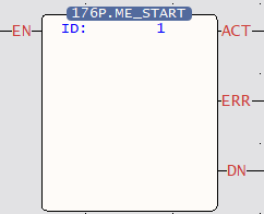
3. Use FUN 176 to enter the number of the motion flow to be executed. The following figure shows the flow chart to enter number 1, which corresponds to the number in Chapter 7-2.
4. It will start to execute the set flow.
7-2 Start Motion Flow
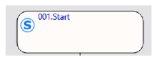
Indicated in the figure below is the Motion Flow starting block where “001” refers to the flow block ID. Such ID is designated by the system and it cannot be changed by the user.
7-3 Select Branch
By selecting the branch, you can execute the designated branch according to the conditions; these conditions can be regarded as the internal variables, and it can also be determined according to the external I/O. By selecting the flow block ID of the desired branch, it allows the user to set the desired ID.
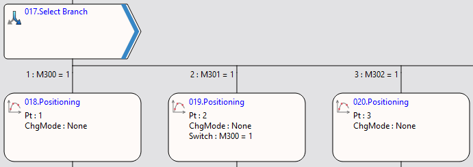
When using Select Branch, you can only enter one branch at a time. For example, M300=1 executes branch 1, M301=1 executes branch 2, and M302=1 executes branch 3.
Note: When M300=1 and M301=1 are established at the same time, the motion flow will enter the first branch on the left.
7-4 Parallel Branch
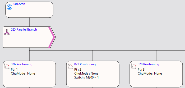
The parallel branch can execute an individual branch. When running the parallel branch, it is not required to set up the conditions and you may access the block to execute all of the following branches directly. The flow block ID of the parallel branch can be set by the user, and the maximum number of branches shall be 20. As per the example in the right-hand side figure, access the parallel branch and then execute all of the following branches.
7-5 Merge
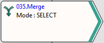
When selecting the branch and the parallel branch with the converging, the selected branch shall appear in pairing type. In this case, it means the branch is the end.
The flow block ID required for merging can be set by the user.
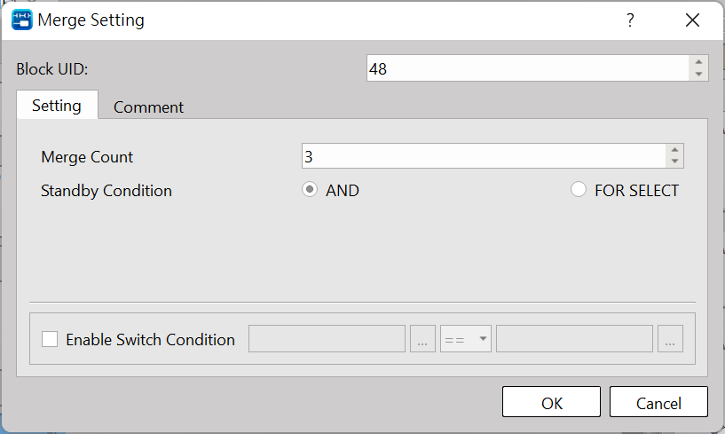
The merged number can be divided into 2–20 branches. The standby condition AND is required for merging the parallel branch, and the selection block is required for selecting the branch merging. By using the jump conditions, you may set the conditions required for jumping to the next flow block. If jump condition remains inactive, you may jump to the next flow block directly. The user may input the notation in the function or the application of such flow block.
When using parallel branch merging function, all branches should be executed at the same time and the sub-flow completed first will enter the converging flow block, waiting for the system to complete other branches.
7-6 Origin Return
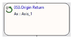
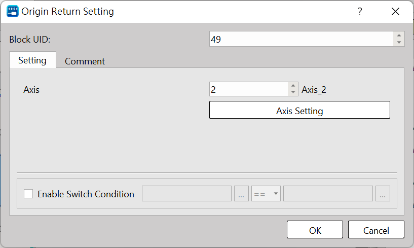
The function block is required for executing the Origin Return of the designated axis. As per the figure below, reset the Origin for Axis_1. If the Origin is duly set, the axis will jump to next flow as soon as M300=1 jumping condition is established.
7-7 Positioning
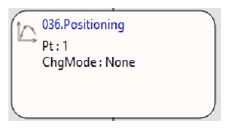
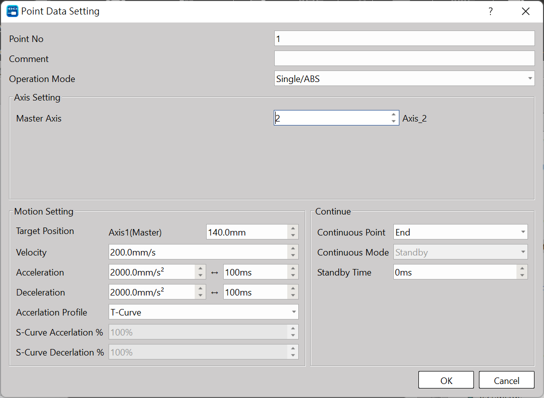
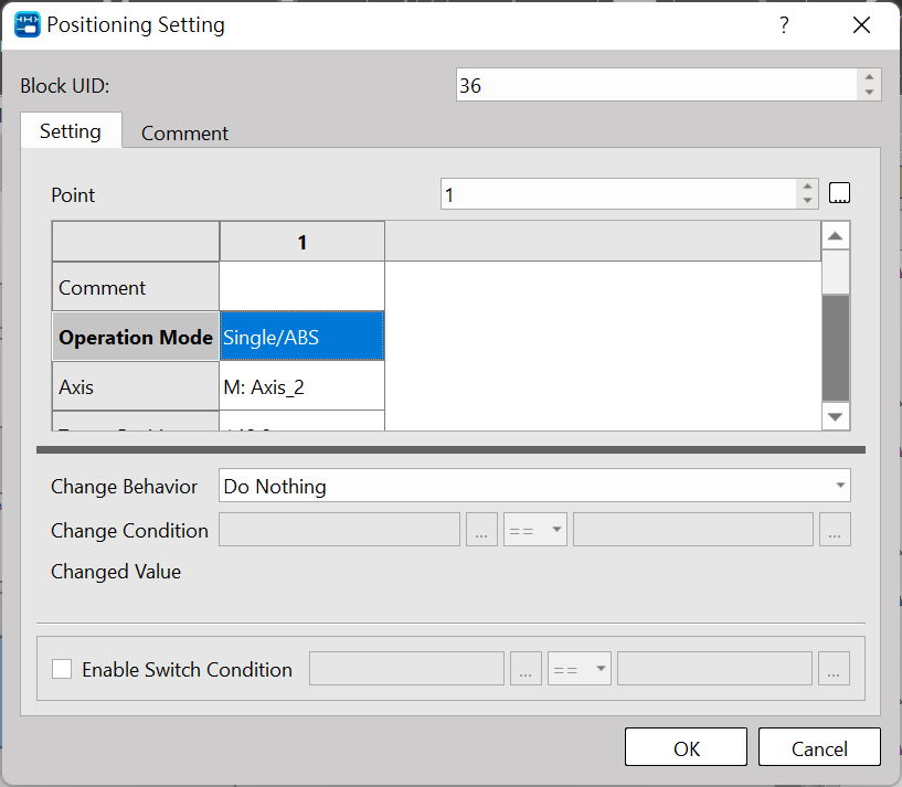
Select the parameters of the designed point for executing positioning control, as per the following:
Flow Block ID: The ID will be assigned by the system automatically, but it can be changed by the user as desired.
Point: As per the corresponding Point Parameter Table, if the motion parameter in Point 9 equals to point parameter 9, then the user may set up the desired point motion parameter in the motion parameters. You may set the point motion related data when writing the flow and then it will be created in the Point Parameter Table by the system automatically.
Change Behavior: No change/Change current coordinate/Change target position/Change speed
Change Condition: The conditions required for changing the behavior. To set the behavior change, then it will be required to set up the change conditions.
Switch Condition: The conditions required for jumping to the next flow block. If jump condition remains inactive, you may jump to the next flow block directly.
7-8 Speed Control
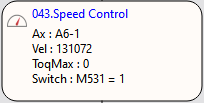
For executing the speed control of the designated axis, per the following:
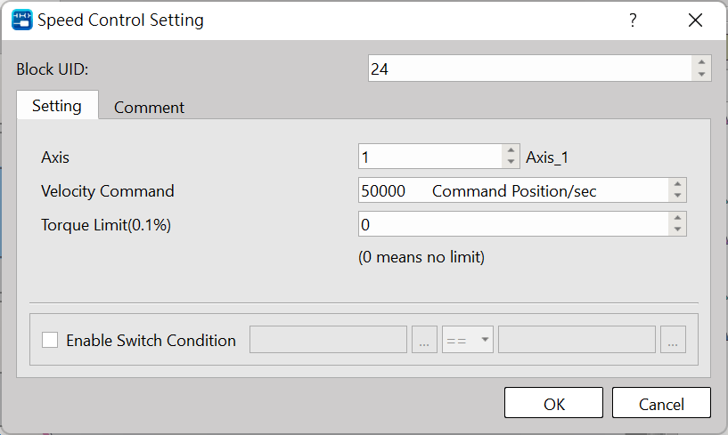
Flow Block ID: The ID will be assigned by the system automatically, but it can be changed by the user as desired.
Axis: The axis required for executing the speed control.
Velocity Command: The speed required for executing the speed control.
Torque Limit: If setting the torque limit at “100”, then the Servo torque will be limited to 10% (0 means limitless).
Switch Condition: The conditions required for jumping to the next flow block. If jump condition remains inactive, you may jump to the next flow block directly. If the jump conditions are not set when using the speed control, the motor will jump to the next flow block immediately after running.
Note: You may input the function or the application notation of such flow block.
Example: When setting at SC3 for one turn =131072 = 1000mm
Assume that you want to set as per turn per second and that the unit of FATEK SERVO speed control is expressed as Pulse per second, therefore you have the following result: 131072 = Running for 131072 pulses per second.
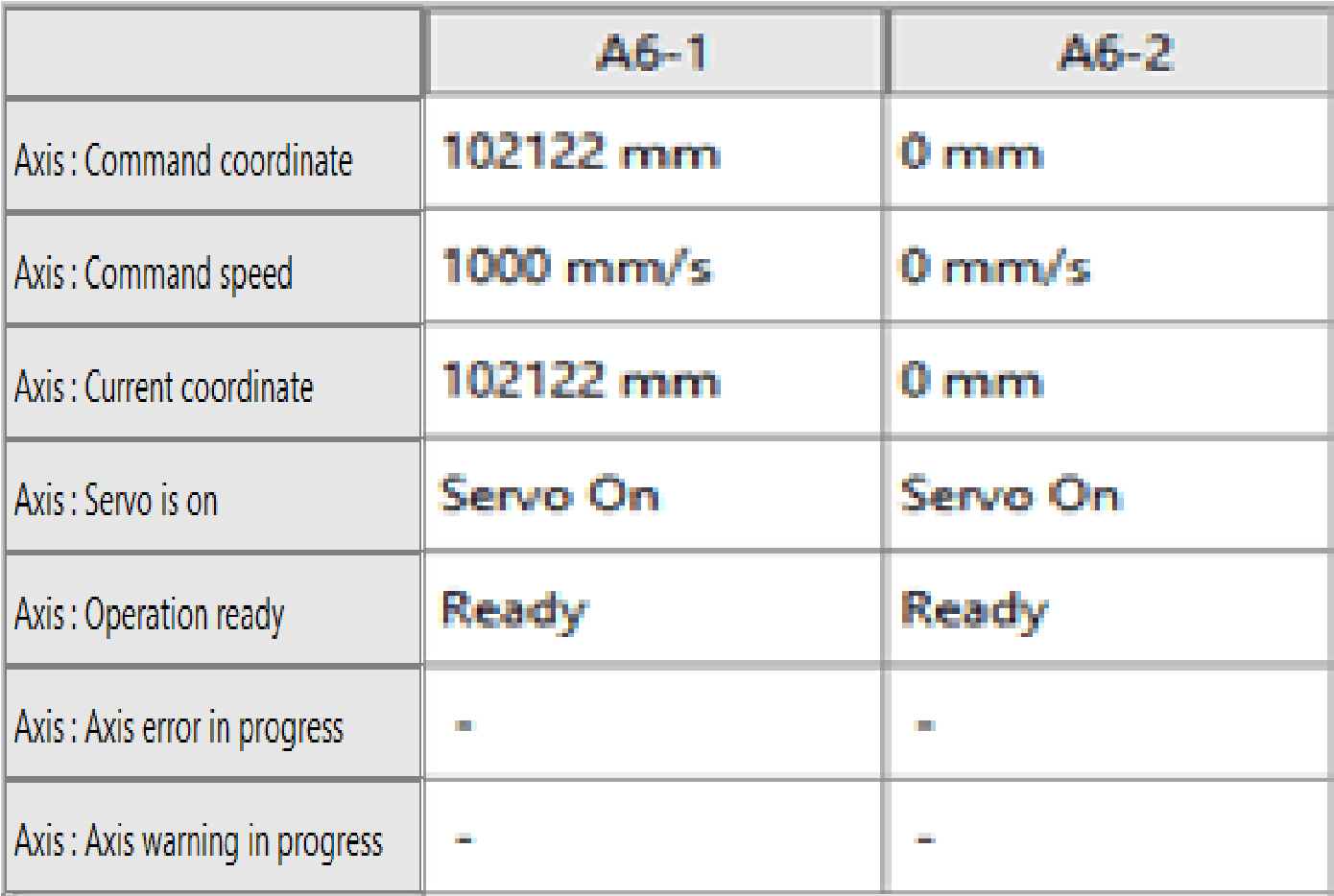
Monitoring Table: Speed setting:
Motion axis speed setting:
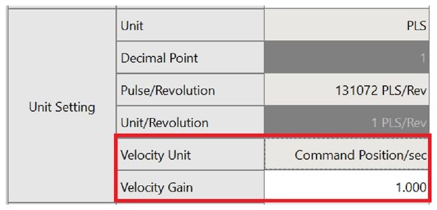
Speed unit: The speed unit used by the monitoring table to display the transmitting speed of the selected Driver.
Speed gain: Min. speed graduation mark transmitted by the selected Driver.
The speed shall be set as (command position/sec)
The gain shall be set as “1”.
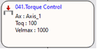
7-9 Torque Control
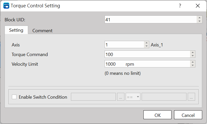
For executing the torque control of the designated axis, per the following:
Flow Block ID: The ID will be assigned by the system automatically, but it can be changed by the user as desired.
Axis: The axis required for executing the torque control.
Torque command: The output torque required for executing the torque control, and the unit is expressed as 0.1%.
Velocity Limit: 0 means limitless
If the switch conditions are not set when using the torque control, the motor will jump to the next flow block immediately after running.
7-10 Standby
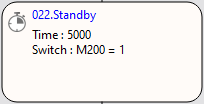
With “Standby”, you may set the delay time and wait for triggering conditions for the Motion Flow.
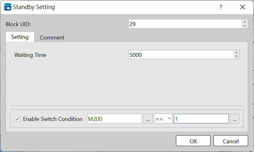
Waiting time: Standby waiting time (unit: ms)
Switch Condition: The condition required for jumping to the next flow block. The system will execute the jumping condition after counting the waiting time.
If the jumping condition remains inactive, then the system will jump to the next flow block directly after counting the waiting time.
Example: When on standby for 5000ms, the system will jump to the next flow block as soon after jumping condition M200=1 is established.
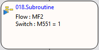
7-11 Subroutine
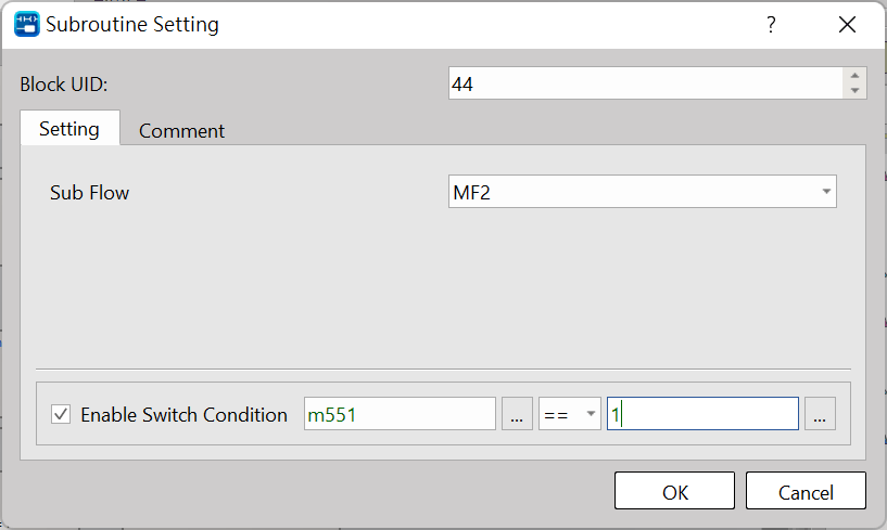
Execute the intended sub-flow, per the following:
Sub Flow: The target sub-flow
Switch Condition: The condition required for jumping to the next flow block.
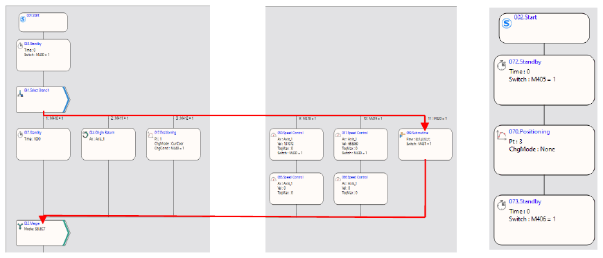
When jumping to the sub-flow for the first time, the sub-flow will jump back to the flow block where the original sub-flow exists and then it will jump to the next flow block in the main flow during the second jumping. If jump condition remains inactive, then it will jump to the next flow block directly.
Example:
1. M420=1: Jump to 69 flow box and then wait at 69 flow block.
2. When the first jump condition reaches M431=1 , it will jump to sub-program for running the program.
3. After running the sub-program, it will jump back to flow block 18 and then wait for next round.
4. When the second jump condition reaches M431=1 , it will jump to flow block 42.
Main Flow Subroutine
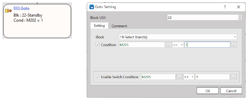
7-12 GoTo
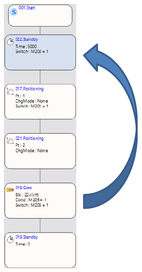
With jumping function block, you may jump to the flow block before or after the same flow block, but you cannot jump to another flow.
Flow Block: For setting the jumping to the designated flow block ID.
Condition: The condition required for jumping to the designated flow block.
Switch Condition: The condition required for jumping to the next flow block.
If jump condition remains inactive, then it will jump to the next flow block directly.
Example:
If M205=1 condition and M205=1 condition are established, it will jump to flow block 22.
If M205=0 condition is not established but M205=1 jump condition is established, it will jump to the next flow block 19.
7-13 Sync
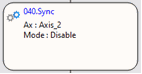
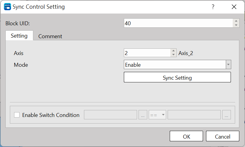
For setting the axis that will be run synchronously.
Flow Block ID: The ID will be assigned by the system automatically, but it can be changed by the user as desired.
Axis: The axis being designated for executing the synchronous running.
Mode: It comprises enable and disenable
Switch Condition: The condition required for jumping to the next flow block. If jump condition remains inactive, then it will jump to the next flow block directly.
 Note: You may input the function or the application notation of such flow block.
7-14 Calculate
|
【Calculate】 |
Calculate (Perform simple digital logic calculation) |
【Calculate】 |
|||
|
Command Description |
|||||
|
Motion Flow Symbol
|
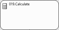
Displyed Info Block UID: The system automatically generates the flow block UID number. |
||||
|
Calculate Setting
|
|||||
|
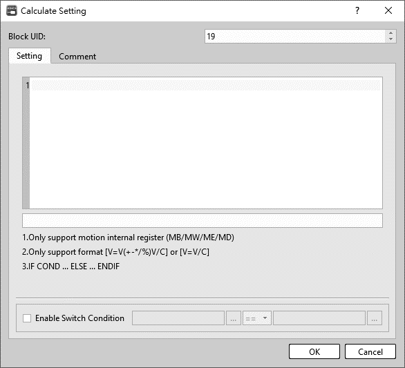
Block UID: The flow block number automatically generated by the system and can be replaced with an unused number. Setting: Editing simple digital logic calculation, starting from the first line and going down. Comment: Comment the functional description of this flow block. Enable Switch Condition: After executing this [Calculate] flow block, use the switch condition to limit the jump to the next flow block. |
|||||
|
Relay and Register
|
|||||
|
Function Description |
|||||
V=V(+,-,*,/,%)V V=V(+,-,*,/,%)C IF COND( ==, > , >=, < ,<=, != )…ELSE…ENDIF
|
|||||
|
Program Exmaple |
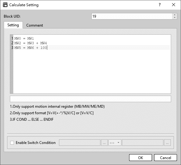
V=V(+,-,*,/,%)V , V=V(+,-,*,/,%)C |
||||
|
{MW0 = MW1 } Copy value from MW1 to MW0 {MW2 = MW3 + MW4 } MW3 adds MW4, and put the result to MW2 {MW5 = MW6 + 100 } MW6 adds 100, and put the result to MW5 |
|||||
|
Program Example |
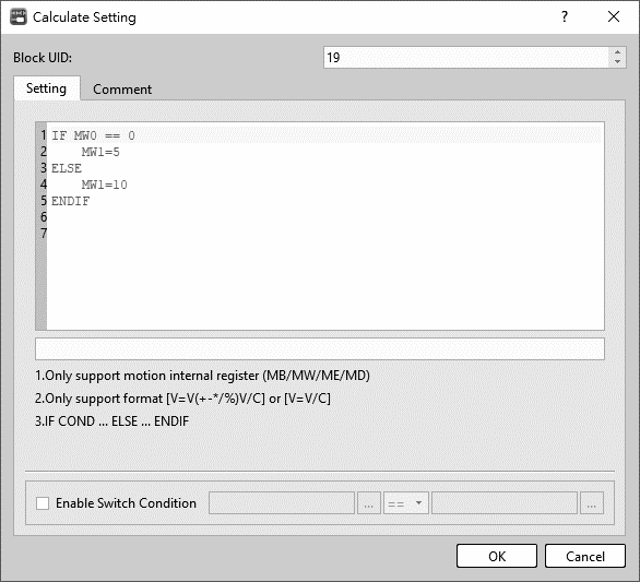
IF COND( ==, > , >=, < ,<=, != )…ELSE…ENDIF |
||||
|
{IF MW0 == 0 MW1 = 5 MW1 = 10 ENDIF} If MW0 is equal to 0, write 5 to MW1, if MW0 is not equal to 0, write 10 to MW1. |
|||||

7-15 End
|
【END】 |
End (The flow block that ends the flow) |
【END】 |
|||
|
Command Description |
|||||
|
Motion Flow Symbol
|
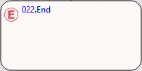
Displayed Info Block UID: The system automatically generates the flow block UID number. |
||||
|
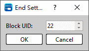
End Setting
|
|||||
|
Block UID: The flow block number automatically generated by the system and can be replaced with an unused number. |
|||||
|
Function Description |
|||||
|
|||||
|
Program Example |
Motion Flow |
||||
|
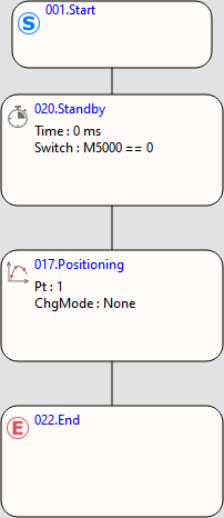
Execute [Positioning] and then execute [End] to switch to this motion flow. |
|||||
Tip: press ← → to switch chapters, Ctrl+K to search