Synchronous Control, Flying Shear
(Synchronization Function Parameter Table/Electronic Cam Setting)
This section describes the basic operation and the parameter setting required for the synchronous control. The synchronous control is also one of the axis motion control functions and it can be effectively applied in the gantry mechanism and flying shear purposes. Therefore, it is a very efficient function when operating under position control mode.
16-1 What is synchronous control?
The synchronous control is a kind of motion control function that can be used for simulating the mechanical cam through the position sensor such as Rotary Encoder. Through the Encoder, it transmits the position information to the PLC where such position information will be decoded by the CPU. Through the synchronous parameter, it will compute the cam (curve) data, gear setting, clutch setting and offset setting and then transmit the resulting data to the Slave Axis.
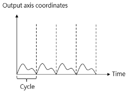
Here, the synchronous Master Axis is termed as Input Axis and the synchronous trailing axis is termed as Output Axis. Based on the coordinate of Master Axis, the cycle of Input Axis will be created in order to repeat the Cam action quickly and effectively.
16-2 Synchronous Parameter Setting Group
Groups will be created for setting the synchronous parameters so that they will be classified according to the designated group in helping the user find out the corresponding parameter.
|
A. Basic Setting |
B. Initialization Setting |
|
C. Master Axis 1 input |
D. Slave Axis 2 Input |
|
E. Master Axis Phase Offset |
F. Variable Gear |
|
G. Main Clutch |
H. Step Angle Offset |
|
I. Cam |
J. Output Filter |
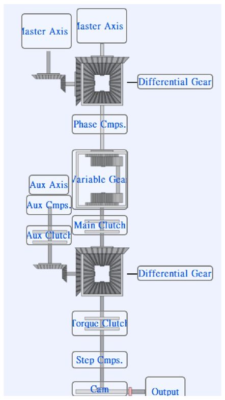
16-3 Introduction of Synchronous Parameter
Basic setting:
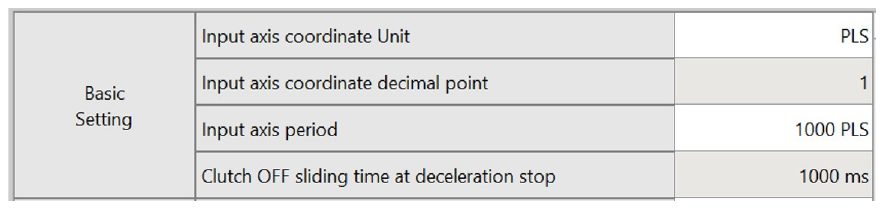
1. Input axis coordinate unit: The unit required for setting and displaying the coordinate, preset as PLS. It comprises the following units for option, pls/mm/deg/inch.
2. Input axis decimal point place: For setting the bit following the decimal point. It is preset as “1” and can be set to 3 places following the decimal point. For example, setting the Input Axis as 100mm per turn. If setting the bit following the decimal point as “0.1”, then the resolution of the input axis cycle can be set to the first place following the decimal point, such as “100.5”.
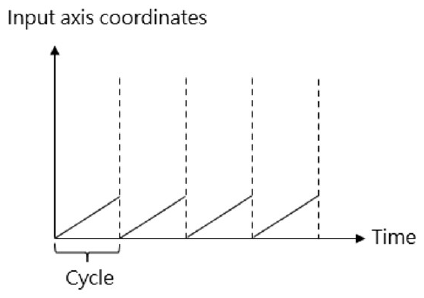
3. Input axis period: Means the cycle quantity of the Input Axis required for the Output Axis to complete one round of Cam motion. By setting the Input Axis cycle, you can execute the Cam action repeatedly, as per the figure below:
4. Clutch OFF sliding time when deceleration stops: The time required for setting the Main Clutch at OFF when stopping the deceleration process. The synchronous control comprises deceleration stop and immediate stop functions and the duration is preset as 1000ms for each. It is also the Stop Mode for the user to release the synchronous control or when an error is detected.
Initialization setting:
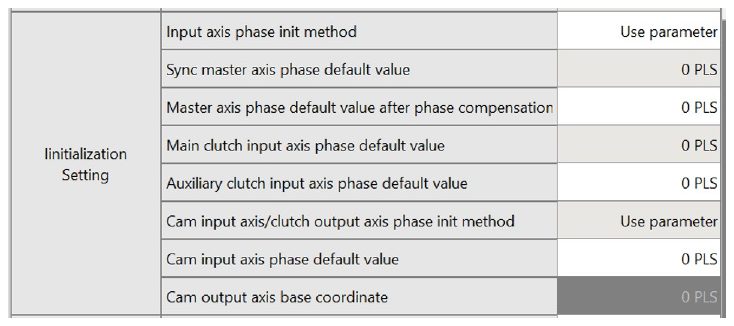
1. Input Axis phase init method: It can be set according to the following three parameters.
- Operating parameter: Execute the initialization according to the Main Clutch input phase preset value.
- Operating Input Axis coordinate: Execute the initialization according to the preset value created for Input Axis coordinate and Main Clutch input phase.
- Maintaining previous value: Initialized as the phase and coordinate being created when previous synchronization ends.
2. Main clutch input axis phase default value: When the aforesaid parameter is set as the operating parameter, access such parameter to create the Main Clutch input phase preset value in order to begin the initialization.
3. Cam input axis/clutch output axis phase init method:
-
- Operating parameter: Execute the initialization according to the Parameter Cam Input Axis phase preset value.
- Operating Cam Output Axis baseline coordinate: Execute the initialization according to the preset value created for Cam Output Axis baseline coordinate and Cam Input Axis phase.
- Maintaining previous value: Initialized as the phase and coordinate being created when previous synchronization ends.
4. Cam input axis phase default value: To be set when setting the aforesaid parameter as the operating parameter.
Example:
When selecting the operating parameter for initializing the phase of Cam Input Axis/Clutch Output Axis and where the preset value of Cam Input Axis phase is set as 100mm, indicated below is the example showing the Input Axis cycle being set as 1000mm:
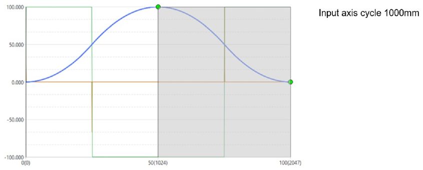
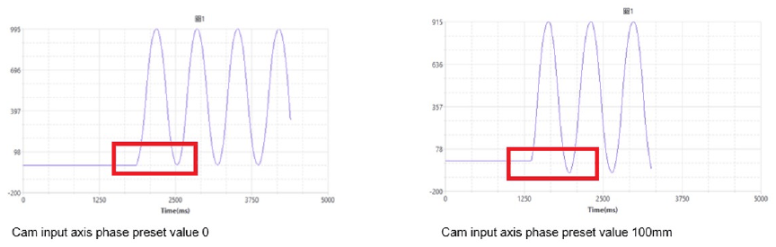
In the figure above, we see that when the preset value of Cam Input Axis phase is set as 0mm and 100mm, the synchronous motion of the Output Axis will start moving by falling behind by 100mm.
5. Cam output axis base coordinate: The aforesaid parameter is used for setting the Cam Output Axis baseline coordinate.
Master Axis input:
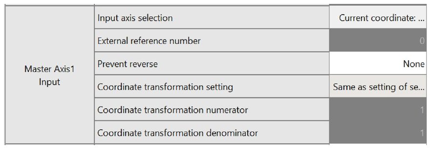
1. Input axis selection
- Operating parameter: Using the external reference Encoder as the Master Axis input.
- Current coordinate: Using the current coordinate transmitted back by the Master Axis as the reference.
- Command coordinate: using the command coordinate of the Master Axis as the reference.
2. External reference number: Selecting Input Axis as the number source of the operating parameter.
3. Prevent reverse (per the schematic below)
- Prevent backward change: Limiting the Slave Axis from reversing
- Prevent forward change: Limiting the Slave Axis from advancing.
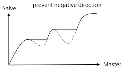
4. Coordinate transformation setting
- Same setting as the selected axis: Maintaining same setting as the selected axis.
- Through synchronous parameter: Use coordinate transformation numerator and denominator for executing the transformation (normally used when the external input value is different from the baseline of current coordinate or command coordinate).
5. Coordinate transformation numerator: Refer to the formula provided below.
6. Coordinate transformation denominator: Refer to the formula provided below.

Differential Gear:
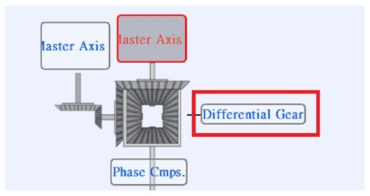
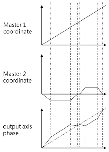
The Differential Gear can be used as the Output Axis coordinate by deducting Master Axis 2 coordinate from Master Axis 1 coordinate, as per the figure below:
Master Axis Phase Compensation:

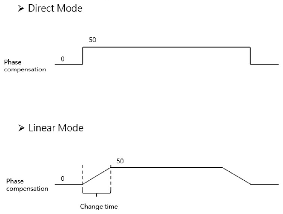
The Master Axis phase offsetting can compensate the fixed deviation and it can be compensated during the motion flow.
1. Compensation command value
2. Compensation change mode
- Direct: Compensating the phase directly
- Linear: Compensating the phase by means of slope.
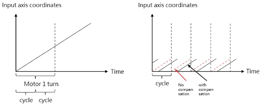
3. Compensation change time: The time required for changing the offset mode to the linear mode, and it will be expressed as “ms”.
Variable Gear:
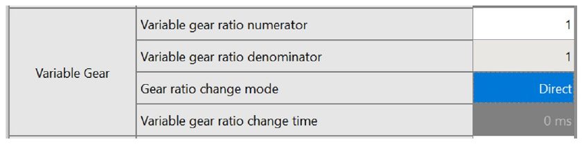
The Variable Gear can be used to convert the Input Axis phase to the Output Axis moving quantity according to the set variable gear ratio.
1. Variable gear ratio numerator: Refer to the formula provided below
2. Variable gear ratio denominator: Refer to the formula provided below

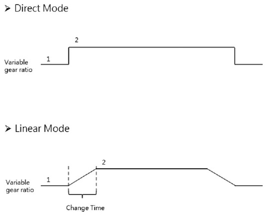
3. Gear ratio change mode:
- Direct: Changed directly when changing the Variable Gear Ratio.
- Linear: When changing the Variable Gear Ratio, it should be executed according to the slope of “Variable Gear Ratio change time”.
4. Variable gear ratio change time: The time required for changing the Variable Gear Ratio mode to linear mode.
** You may change the Variable Gear Ratio through the program.
Main Clutch:
Clutch ON/OFF controls the synchronization or operation stopping for the Output Axis phase.
The clutch connection and disconnection can be executed with the following three methods: direct, sliding and slave.
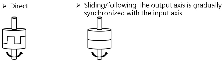
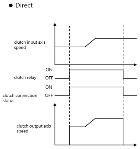
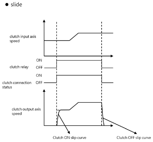
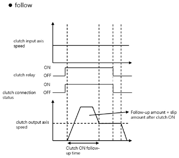
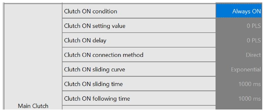
- The Main Clutch ON condition comprises the following methods:
- Constant ON: Maintaining the connected status.
- Constant ON (single direction forward)
- Constant ON (single direction backward). Its concept is the same as constant ON (single direction forward).
- Clutch control relay (level): Set to ON when the axis synchronous master clutch switch M10604 + (40*n-1) or axis synchronous auxiliary clutch switch M10611 + (40*n-1) is high, and set to OFF when it is low.
For example, if M10604 is continuously ON, the clutch is ON, which is the level function. - Clutch ON Request Relay (Edge): Set ON when the state of axis synchronous main clutch switch M10604 + (40*n-1) or axis synchronous auxiliary clutch switch M10611 + (40*n-1) becomes high.
For example, when the upper edge of M10604 triggers ON, the clutch will continue to be On, which is an edge function.
- Clutch input axis phase: When the input phase reaches the ON setting value, the clutch starts to transmit the variation
- Clutch ON setting value: Enabled when the clutch ON condition is set to “Clutch Input Axis Phase”
Settable range 0-4294967295
- Clutch ON delay: After the ON condition is met, the input phase is set to ON after the ON delay setting value.
Settable range 0-4294967295
- Clutch ON connection mode:
Direct: Indicates the way the clutch is directly connected
Slide: The output phase accelerates smoothly until fully synchronized, ignoring errors in the process
Follow: The output phase accelerates smoothly until it is completely synchronized, and the error in the compensation process is added to the distance of the compensation following amount before it is set to ON
- Clutch ON slide curve: Indicates the error in the slide process.
※If the input axis changes to 0 during the sliding process, set it to ON directly
- Clutch ON slide time: Set the specified time. Indicates that the sliding process needs to be completed within the instruction time, ignoring the error in the process.
- Clutch ON follow time: unit is ms
- Clutch ON follow amount: Indicates the error in the compensation process, and it is set to ON after adding the distance of the compensation follow amount.
Settable range 0-4294967295
- Clutch OFF Condition:
Servo off: No OFF condition
Synchronous OFF Register (Edge): Set to OFF when state of axis synchronous main clutch switch M10604 + (40*n-1) or axis synchronous auxiliary clutch switch M10611 + (40*n-1) goes low.
Input axis phase: Set to OFF when the input phase reaches the OFF setting value.
Output axis movement: Set to OFF when the phase change of the output shaft reaches the OFF setting value.
Output axis phase: Set to OFF when the output phase reaches the OFF setting value.
Settable range 0-4294967295
- Clutch OFF Setting Value:
Enabled when the OFF condition is set to input axis phase, output axis movement amount, and output axis phase.
Settable range 0-4294967295
- Clutch OFF Delay:
Indicates that after the OFF condition is met, the input phase is set to OFF after the OFF delay setting value.
Settable range 0-4294967295
- Clutch OFF Connecting Method:
Direct: Indicates the way to set OFF
Slide: Slide means that the output phase is smoothly decelerated until completely separated, ignoring the error in the process.
- Clutch OFF slide curve: Settable range 0-4294967295
- Clutch OFF slide time: Unit is ms, settable range 0-4294967295
Step Angle Compensation:
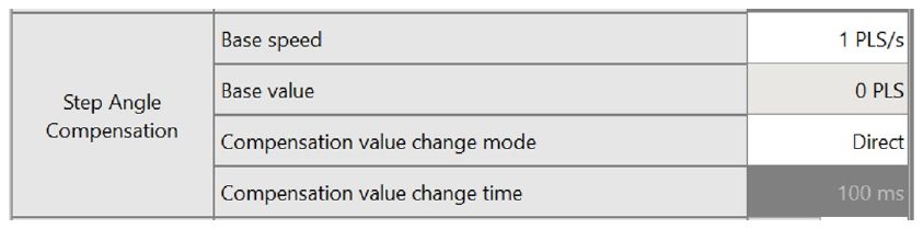
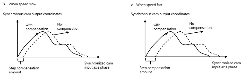
The Step Angle offset is used to compensate the delay when the Cam is operating at different speeds.
Base speed: Refer to the formula provided below.
Base value: Refer to the formula provided below.
|
Step Angle Compensation = Input Axis speed x |
Base value |
|
Base speed |
Compensation value change method
- Direct: Change directly
- Linear: Change the slope of [Compensate Change Time].
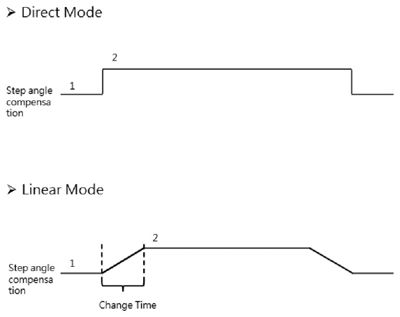
Compensation value change time: The time required for changing the offset value change method as Linear Mode (unit: ms)
Cam:

Cam data No.: Setting the ID for the Cam that will be used by the Slave Axis.
* If the Cam data is coded as “0”, then it will be irrelevant to the cycle and Cam travel values of the Input Axis. Such data will be used to execute the proportional (1:1) action for Input Axis cycle and feeding quantity.
Cam stroke: The travel of the Slave Axis
Synchronous contact ID: (not supported for now)
Output filtered wave:

When using the output filtered wave, a filter device can be added for the Cam output.
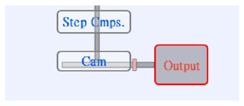
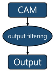
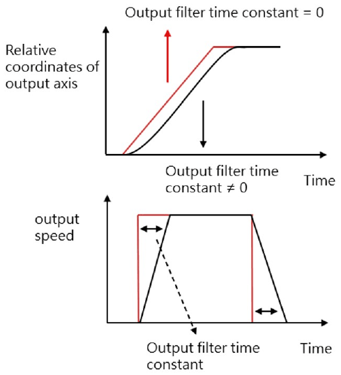
The output filtered wave can inhibit the frequency fluctuation. Even though significant change has occurred at the axis position within a short period of time, the frequency change of the Slave Axis can be inhibited through output filtered wave function.
* If the output filtered wave is too large, it may cause the delay of moving quantity. Therefore, it should be set by considering the delay of moving quantity.
16-4 Synchronous Cam Setting
Please use UperLogic to set the Synchronous Cam. Indicated below is the software homepage after opening the project and it also introduces the Synchronous Cam related functions and setting.
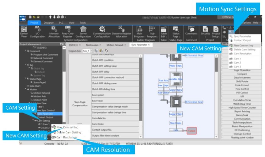
To set the Cam in the homepage, press the mouse right key and click Add New Cam and then the resulting Cam curve will be indicated as in the figure below.
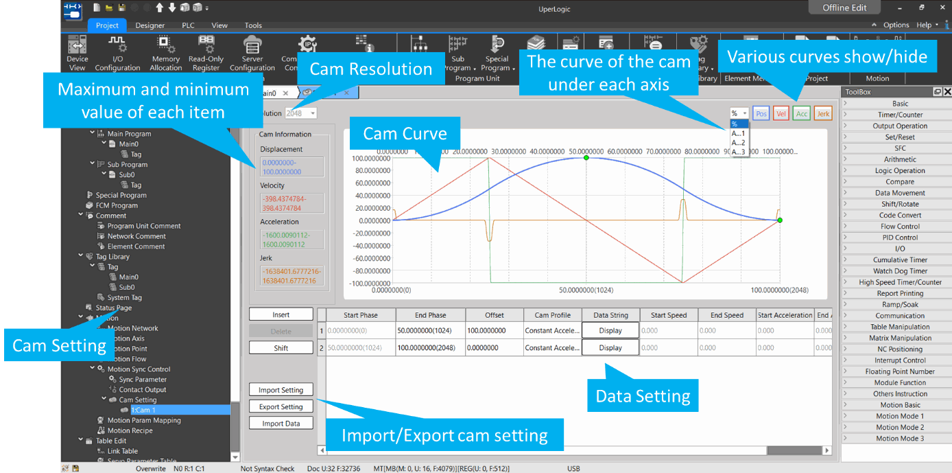
Cam resolution: The resolution of Cam curve. The higher the resolution, the smoother the curve.
Based on the point and the Cam profile set by the user, the software will calculate the position of each resolution. Listed below is the relationship of Cam resolution and maximum Cam number. The lower the Cam maximum number, the better the Cam resolution; on the contrary, the higher the Cam maximum number, the lower the Cam resolution.
|
Cam resolution |
Maximum number of cams |
|
2048 |
16 |
|
4096 |
8 |
|
8192 |
4 |
|
16384 |
2 |
|
32768 |
1 |
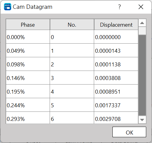
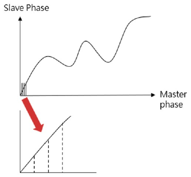
Example: If two sets of Cam curves are used, then the Slave Cam curve of each Master Axis cycle will be segmented into resolution for 16384 points. The finer the resolution, the smoother the curve.
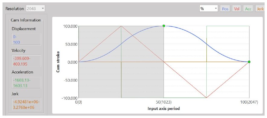
The curve of Cam under different percentage ratios.
- Percentage Mode
- The Input Axis travel is displayed with percentage (Axis-X)
- The Output Axis travel is displayed with percentage (Axis-Y)
Per the figure below:
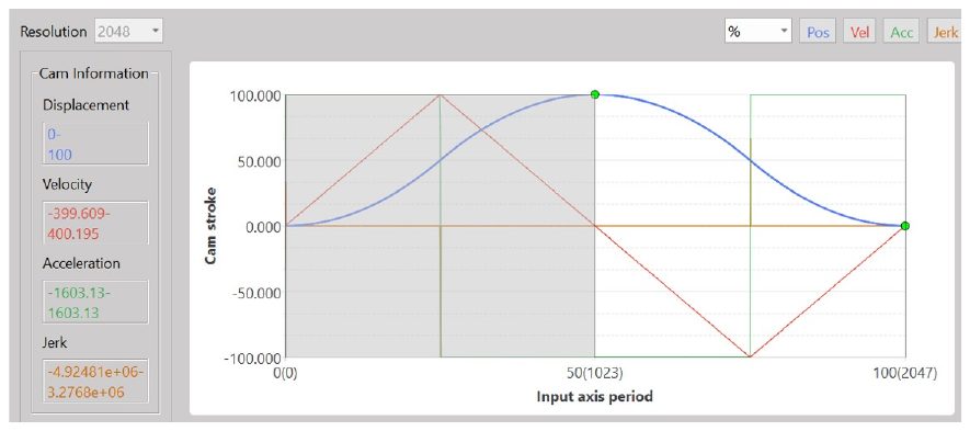
- Such Cam will be used with Axis-2
- Input Axis travel: 1000mm (Axis-X)
- Output Axis travel: 1000mm (Axis-Y)
Per the figure below:
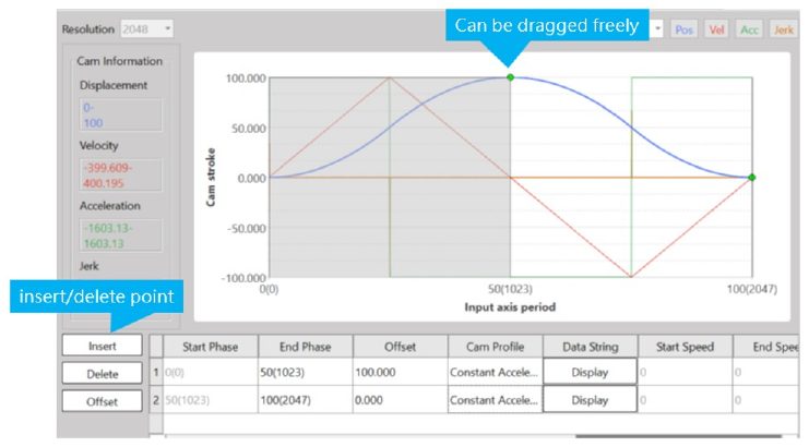
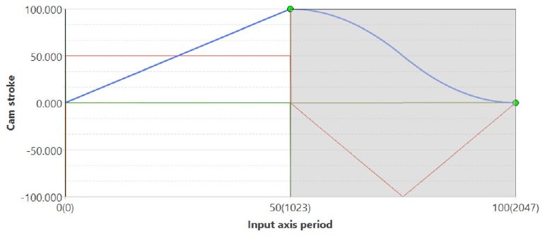
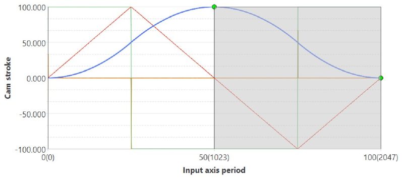
To implement the Electronic Cam curve, click the plug-in button and a point will appear in the picture automatically. The user may drag the position of such point directly with the mouse, and the user will also be allowed to change the set value through the table highlighted with the red frame in the figure below.
Definition of Cam curve color:
Blue line: Position
Red line: Speed
Green line: Acceleration
Orange line: Jerk
16-5 Characteristics of Cam Profile
Described below are the characteristics of Cam profile:
The characteristics of Cam profile curve are mainly determined by velocity, acceleration and jerk. Described below are the representing characteristics and meaning:
Velocity (V): The physical quantity used to describe the motion speed and direction of the object and it is proportional to the motion quantity of the Workpiece (P=mV). In terms of control, the faster and heavier the load, the more difficult the control. Steadier control can be achieved by reducing the maximum value of velocity.
Acceleration (A): The acceleration is the rate of change between velocity vector and time, and it is used to describe the velocity direction and the speed resulting from the change of size. Because F=mA is presented in proportional type, the higher the acceleration, the larger the resulting torque and the easier the interference. Therefore, it should be appropriately adjusted according to the required load and inertia.
Jerk (J): It is also termed as jerk, impulse and jump, etc., and is the physical quantity used to describe the changing speed of acceleration. The Jerk is determined by the acceleration changing rate and time. The bigger the jump, the more violent the resulting torque changing rate, and it may lead to collisions or vibrations as well.
When using the Cam profile, it should be selected depending on the intended purpose, such as heavy load control in order to reduce the maximum speed. When executing the high-speed control, it can stabilize the control by reducing the jerk so as to avoid the vibration that may affect the stability and the accuracy of the control.
Provided below are the purpose and description of Cam profile:
- Constant velocity line: Normally used in reducing the speed and executing the iso-linear motion. It is suitable for controlling the heavy load and low-speed running.
- Uniform Acceleration: When the maximum value of the acceleration reaches its minimal level, the smallest torque will be produced. Because the speed of uniform acceleration will be discontinued at the point when shifting from acceleration to deceleration, it is therefore more suitable for medium speed.
- Cycloid: The cycloid speed and the acceleration are continual. It is suitable for high-speed and light-load purposes.
- Simple harmonic: Because the acceleration at the phase starting and ending point will be discontinued, it would be vulnerable to vibration and is not suitable for high-speed purposes. When executing the turn-around action, it will be suitable for continuous back-and-forth action.
- Deformed constant velocity: It is suitable for medium-low speed and heavy-load purposes; the curve characteristics will become steeper in acceleration and displacement change.
- Deformed trapezoid: The Cam curve widely used. Due to smaller maximum acceleration value, it is suitable for high-speed and light-load purposes.
- Deformed sinusoidal: Such curve is presented in balanced smooth type. Compared to the deformed trapezoid curve, it will inhibit the maximum speed value. Therefore, it will be safe for use in unknown load or variable purposes.
- Trapezoid: The maximum speed value of trapezoid curve is higher. Because the acceleration will be executed continuously, it will not produce vibration and is suitable for light-load and high-speed purposes.
- Single stay cycloid m=1: The cycloid curve applied by single stay. Because it will not become “0” acceleration at the ending phase, it can reduce the maximum value of speed and acceleration; further, the change of acceleration curve will become smoother. Therefore, it will be suitable for high-speed purposes.
- Single stay cycloid m=2/3: Compared to single stay cycloid m=1, its acceleration curve will become smaller during deceleration. Therefore, it can reach the ending phase in a much smoother way.
- Single stay trapezoid curve: Because it will not become “0” acceleration at the ending phase, it can achieve a lower maximum speed and acceleration value. Therefore, it will be suitable for light-load and high-speed purposes.
- Single stay deformed sinusoidal: Because it will not become “0” acceleration at the ending phase, it can reduce the maximum speed and acceleration value. It belongs to a smoother curve showing lower speed and acceleration. Therefore, it will be suitable for medium-load and high-speed purposes.
Tip: press ← → to switch chapters, Ctrl+K to search