The default Window Configuration of FATEK FvDesigner is as shown below:
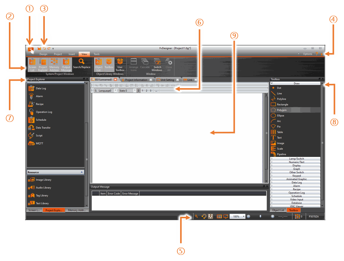
Figure 10 FATEK FvDesigner Window Configuration
1. File
2. Project function area
3. File shortcut bar
4. Software interface appearance options and version information
5. Software status bar
6. Project shortcut toolbar
7. Project system window
8. Objects and toolboxes
9. Project screen window area
2.1 File Tags
2.1.1 File
The File Window will appear after pressing the  icon, as shown below.
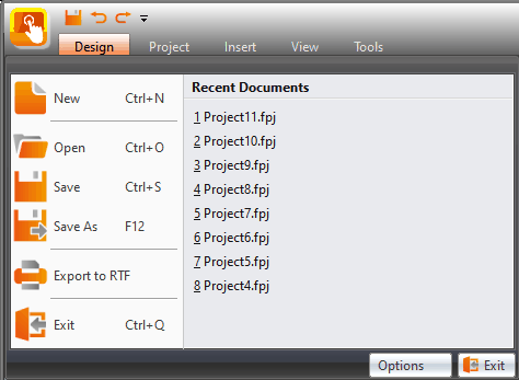
Figure 11 Toolbar–File
Table 4 File Options
|
Function |
Description |
||||||||||
|
【New(N)】 |
Close the current project and open the Project Wizard. A reminder window will appear to ask the developer to save the project if the current project was not yet saved. |
||||||||||
|
【Open(O)】 |
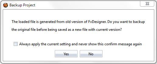
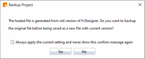
Select the path and open a project. A reminder window will appear to ask the developer to save the project if the current project was not yet saved. If opening an existing project, a dialog will appear asking the user if a backup should be created. If “Yes” is selected, a backup file will be created. For example, if the file name is Project1.fpj, the backup will be created under a folder named “backup” created in the same path. The backup file will be named Project1.fpj.bak. If “No” is selected, no backup will be created.
|
||||||||||
|
【Save(S)】 |
Save the currently editing project. |
||||||||||
|
【Save as(A)】 |
Select a path and save the current project as a new file. |
||||||||||
|
【Export to RTF】 |
Creates a document detailing project information in an RTF file that can be opened in text editors such as Microsoft Word. Information in the RTF file includes the HMI model used, memory usage, and screen information. |
||||||||||
|
【Recent Documents】 |
Open recently used project. These project names will be displayed on the right of the window; if the cursor is moved on top of a file name, the file path will be displayed. |
||||||||||
|
【Option(I)】 |
Open【Option】, to set software environment related settings.
|
||||||||||
|
【Exit(X)】 |
Close the current project and the program. A reminder window will appear to ask the developer to save the current project if the current project was not yet saved. |
2.2 Ribbon
The Ribbon is a user interface that uses panels and tab pages as the architecture; functions will be displayed with icons in the Window below according to different options selected. There are five tabs in this section:【Design(D)】,【Project(P)】, 【Insert(I)】,【View(V)】, and【Tools(T)】.
2.2.1 Design(D)
【Design(D)】allows developers to edit the object configurations within the work space. It provides general clipboard functions, object format settings and provides frequently used objects to insert into the work space. Theme is used to apply settings to specifically selected objects in the window and change their appearance. Detailed descriptions of each function are as follows:

Figure 12 Design(D)
Table 5 Introduction to Ribbon User Interface Functions
|
Function |
Description |
||||||||||||||||||||||||
|
【Clipboard】 |
Basic functions related to designing objects.
|
||||||||||||||||||||||||
|
【Screen】 |
A design screen can be quickly added and change screen.
|
||||||||||||||||||||||||
|
【Basic Setting】 |
Provides basic object settings for users to edit comments, location and size of the object.
|
||||||||||||||||||||||||
|
【Font】 |
Provides basic settings for users to edit the font, size and color of text. |
||||||||||||||||||||||||
|
【Text Align】 |
Provides basic settings for users to edit the position of text in an object. |
||||||||||||||||||||||||
|
【Theme】 |
Users can use this function to apply settings to the specifically selected objects in the work space to change their appearances.
|
||||||||||||||||||||||||
|
【Format】 |
Provides object format functions to allow users to select multiple objects and organize the typesetting of the screen objects, including alignment, spacing, size adjustment functions etc.
|
||||||||||||||||||||||||
|
【Draw】 |
Select the object then you can draw it on the workspace. |
||||||||||||||||||||||||
|
【Object】 |
Select the object then you can draw it on the workspace. |
2.2.2 Project(P)
This field provides project related function settings, and it is divided into the following three parts:
【Execute】Compiles the project file into a running package, or decompiles the running package into a project file.
【Transfer】is related to file transfer; It can download the compiled running package onto the HMI for running or acquire the running package from the HMI and upload it onto the computer. Users can also make an USB update file to replace the running project on HMI.
【Run】opens the simulation window to run the current project, include off-line simulation and on-line simulation.
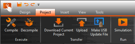
Figure 13 Project
2.2.2.1 Compile
The compile function can generate the project running package used by the software download tool.
Before v1.6.34, xxx.cfrp will be generated. From v1.6.34, the compiled file will have two files: xxx.cfrplst & xxx_G01.cfrp. Both files must be in the same folder when downloading!
After compilation, the output window will display information such as compilation results and memory configuration status. Before executing the simulation or download function, it will ask to save the project and then compile and generate the project runtime package.
Table 6 Compilation Output Window Related Information
|
Information |
Content |
|
【Project】 |
The compiled project file. |
|
【Date】 |
Compiled date and time. |
|
【Running Package】 |
The location to create the running package file (*.cfrp). |
|
【Memory Usage】 |
Total memory size that has been used. The remaining space of the project file. |
|
【Project Capacity】 |
The total used size of the project file. Space remaining for the running package. |
|
【Compile Output】 |
Number of errors Number of warnings Compile Output: Success/ Failed. |
|
【Recommended Model】 |
When the FvDesigner model chooses PC, this option will appear, and according to the number of registers and links used in the project, then recommended which level IGU-FvRT can be used. |
2.2.2.2 Font Replace Manager
During compilation, when the system detects that the input text does not match the selected font, the【Font Replacement Manager】will pop up to prompt the user to change the font. If the correct font is not replaced, the project will be downloaded to the HMI. Afterwards, the text may not be displayed.
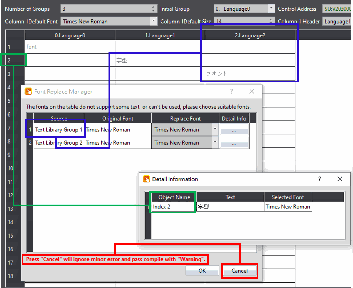
Figure 14 Font Replace Manager
As shown in the figure above, the font replacement manager pops up. We can know from the Detail information what text is detected as an error, and know its group and line number; after modifying it in【Font Replacement Manager】, press OK that the check project will need to be recompiled, and the user can also choose to cancel to skip the font check.
2.2.2.3 Decompile
The decompile process can be used on the running package (.cfrp) uploaded from the HMI to extract the project and attached recipes and fonts. The decompile function can be found in the【Project】function tab of the Ribbon task bar on top of the FvDesigner; click on【Decompile】to start. Please refer to the Chapter 21–Uploading, Downloading, and Simulating an HMI Project for more details.
2.2.2.4 Upload & Download
Data transfer can be performed for projects through USB or Internet/Serial cable connection. Clicking on the Download function will automatically compile and save the project to the HMI. Clicking the Upload function will upload the running package running on the HMI onto the computer. If users want to view the contents of the running package after upload is complete, the decompile function can be used to extract contents from the running package.
The HMI network IP information must be set when using Internet transfer. The auto-search function can be used if the user does not know the IP information; the software will search for FATEK HMI devices on the local network and display the device IP information found in a table. Select the target device’s IP to perform data transfer.
The transfer function is password protected; the upload or download password must be set before transferring and this password will be checked during connection. Communication will only be performed if the password is correct.
Please refer to the【Upload】and【Download Current Project】sections in Chapter 21–Uploading, Downloading, and Simulating an HMI Project for details.
2.2.2.5 Make USB Flash Drive Update File
This function allows the user to generate a dedicated USB update file in the specified path.
Before v1.6.34, xxx.uferp will be generated, put this file into the root directory of the USB, and then insert the USB into the HMI and it will ask whether to update the project.
Starting from version v1.6.34, the compiled files will appear xxx.uferplst & xxx_G01.uferp. Both files should be placed in the root directory of the USB. After inserting the USB into the HMI, the system will ask whether to update the project. Click Yes After selecting any file extension, the file will start to be updated.
Please refer to the Chapter 21–Uploading, Downloading, and Simulating an HMI Project for details.
2.2.2.6 IGU Setting
When FvDesigner choose PC model, will appear USB Dongle seeting option, figure as shown below, this option is mainly to set the customer ID of IGFU-FvRT(USB Dongle), insert IGU-FvRT(USB Dongle) into PC USB port, then set the customer ID through this option, the customer ID in the project and the customer ID of IGU-FvRT(USB Dongle) need to be the same, then the FvRT can excute correctly. For more detailed operation step please refer to FvRT manual.
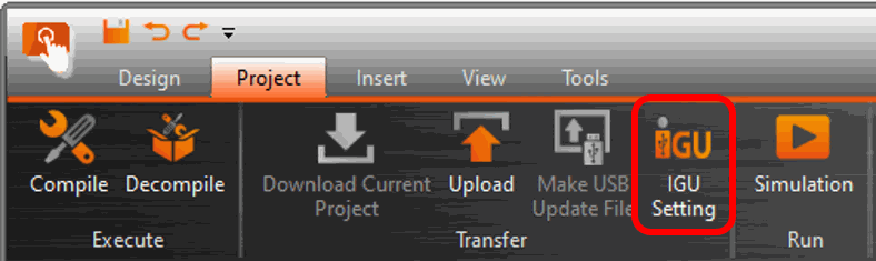
Figure 15 IGU Setting List
2.2.2.7 HMI detects USB Flash Drive plugged in
When HMI detects USB flash drive is plugged in, for operator to know clearly, the message will show on the screen of HMI as figure shown below, to remind operator.

Figure 16 HMI detects USB flash drive is plugged in
When HMI detects USB flash drive is removed, for operator to know clearly, the message will show on the screen of HMI as figure shown below, to remind operator.

Figure 17 HMI detects USB flash drive is removed
The USB flash drive formats that HMI can read and write include FAT32, NTFS, and support support most brands with a storage capacity of 2 ~ 32G. After the system version OS 2.0.22, it supports exFAT format and 64G.
2.2.2.8 Simulation
The project must first be compiled to generate the running package file before the simulation is run. Simulations are divided into Offline Simulation and Online Simulation; their descriptions are as follows:
Offline Simulation: Does not require connection of PLC and HMI equipment; the screens of the running package can be operated directly.
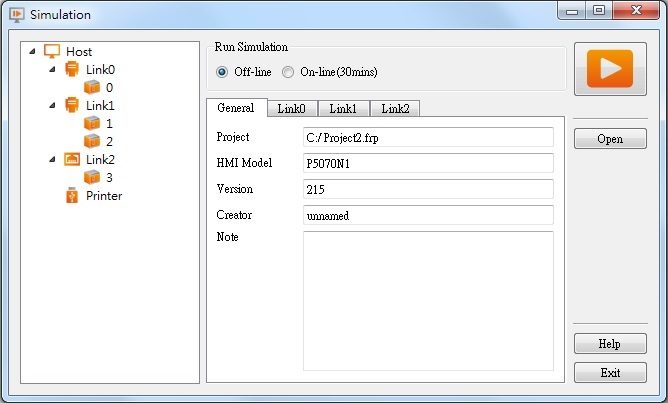
Figure 18 Offline Simulation
Online Simulation: PC and PLC connected; running package is executed on the PC and communicates with the PLC.
Port is the COM Port of PC
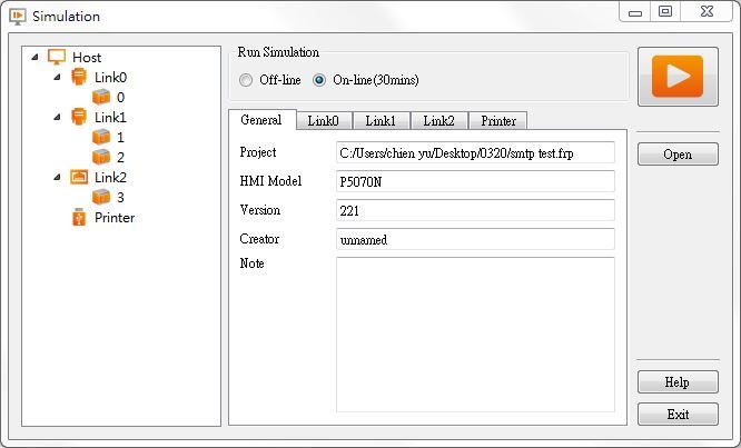
Figure 19 Online Simulation
Please refer to the simulation chapter in Chapter 21–Uploading, Downloading, and Simulating an HMI Project for details.
2.2.3 Insert(I)
This field allows users to quickly add screens or functions; they can be added by pressing this button, in which includes:
【Screen】,【Device】,【Data Log】,【Alarm】,【Recipe】,【Schedule】,【Data Transfer】and【Script】
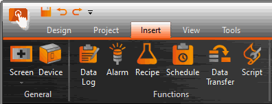
Figure 20 Insert
2.2.4 View(V)
The View tab of the Ribbon contains functions related to the appearance of the application; the【System/Project Windows】will be placed on the left except【Search/Replace】and the【Object/Library Windows】will be placed on the right.
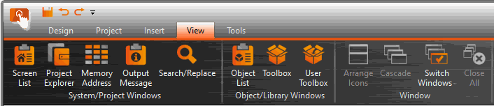
Figure 21 Window
Use the mouse to drag the working space and the FvDesigner will display the window configuration reminder; move the mouse to the configuration reminder and the workung space will be placed at the position clicked. The FvDesigner has a 【User Habit Log】function that will record the developer’s window configuration position on the system so that the workung space configuration will be configured to the same positions as the previous development environment every time the project is opened for development.
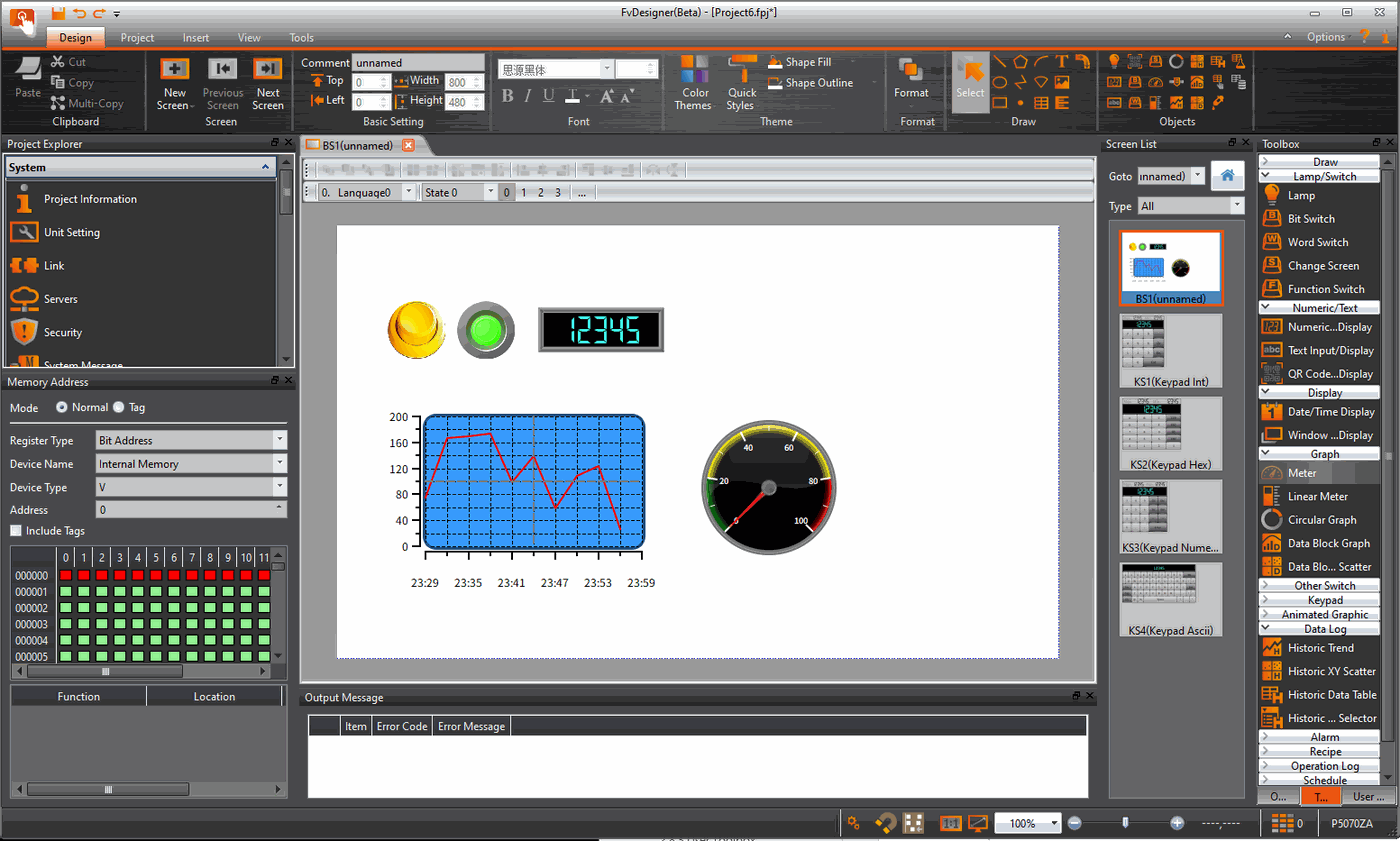
Figure 22 Configure Operating Window Position
2.2.5 Tools(T)
The Tools tab including built-in applications as follow:
【File Transfer】: allows users to connect with PC via USB drive upload/ download and transfer files from HMI to PC for viewing or backup
【Pass Through】: allows users to communicate and connect to the PLC through the HMI.
【PLC Resource Review】: helps users to find the supported PLC driver program version information, the internal single points of the PLC allowed for access, and register information.
【Remote System Setting】: allows users to enter the IP address of a HMI present in the local area network and control it remotely.
【FATEK PLC Transfer Encrypt Tool】: When download FATEK PLC project through HMI, can generate Fatek PLC Transfer Project or Singal Pass Password.
【FBF Reader】: Reader that can read FBF file.
【Install USB Driver】: automatically detects the system information and installs the appropriate USB drivers.
【Download】: Download the other running packages.
【iAccess】: Do upload, download, passthrough, and other services through cloud service.
【USB Security Key】: Can generate USB security key.
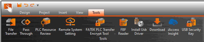
Figure 23 Tools
2.3 Shortcuts
Allows users to set frequently used functions to be displayed here, making it easier for users to operate.
【New】,【Open】,【Save】,【Undo】and【Redo】

Figure 24 Shortcuts
2.4 Interface Appearance Options
【Interface Appearance Options】(Top Left) provides customized interface appearance settings, allowing users to minimize or maximize the work space and change the color and text of the interface. There is also a help function and the program version information is also provided here.

Figure 25 Interface Appearance Options
Table 7 Interface Appearance Options
|
Display Item |
Description |
|
|
Pressing this button will minimize the work space and pressing it again will maximize the work space. |
|
【Options】 |
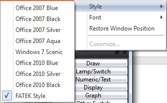
Choose the style and font of the interface. 【Style】 Choose the style of the interface.
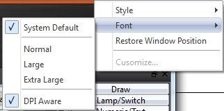
【Font】 Choose the font size of the interface.
【Restore Window Position】can restore the workung space, you can click this option, the work window will be restored to the system default location.【System/Project】except【Search/Replace】will on the left, 【Objects/Resource Library】will on the right. 【Customize】provide customize option. |
|
|
If you want to inquire about the related settings for the use of the software, you can press this help, press it will display the user manual for the query software related functions |
|
|
Displays software version information.
|
 【Maximize/Minimize ribbon】
 【Help】
 【About】
2.5 Status Bar
The【Status Bar】displays information on the work space window, the window resolution, HMI product specifications and type, and other information.

Figure 26 Status Bar
Table 8 Status bar
|
Display Item |
Description |
|
【Show Name and Address】 |
Pressing the gear brings up a window with the following options: 【Show Name and Address】 Overlays the name and register being controlled for each component in the project. 【Show Quicklaunch Toolbar】 Shows/hides the quicklaunch toolbar present above the editing screen. 【Search/Replace】 Whether to displays Search/Replace setting window. Please refer chapter30-Search/Replace for more detail. 【Set Name and Address Display】 Properties for the Name and Address display. User can hide/show the name or address displayed and change text properties such as address color, background color, opacity, font and size. |
|
【Snap Alignment】 |
While moving objects, this function assists the user to align nearby objects. |
|
【Grid Alignment】 |
【Show Grid】 Can switch whether to display grid lines in the working space. 【Show Grid Display】 Set the grid type, color, and inteval. 【Add Grid Interval】 Add grid by 5 offset. 【Substract Grid Interval】 Substract grid by 5 offset. |
|
【Actual Size】 |
Zoom the screen window ratio to 100%; this will only be displayed when the editing section of the screen is open. |
|
【Fit Visible】 |
Adjustable to Zoom the screen window ratio to the same size as the visible range; this will only be displayed when the editing section of the screen is open. |
|
【Screen Display Ratio】 |
Zoom the screen window ratio between the range of10%–550%; this will only be displayed when the editing section of the screen is open. |
|
【Cursor Position】 |
Display the X and Y coordinates of the mouse in the editing section of the window; the point of origin is the top-left corner of the window. This will only be displayed when the editing section of the screen is open. |
|
【Used External Registers】 |
Display the used of the external registers. |
|
【HMI Model】 |
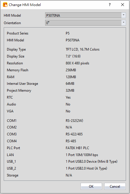
Product model information: Pressing this button will display the information of the current product model. Ex: P5070NA. |
2.6 Quicklaunch Toolbar
The【Quicklaunch Toolbar】provides quick access to common tools including copy/paste, moving objects between layers, grouping objects, alignment options, and language and state switches. Can be displayed above or below the window edit area.

Figure 27 Quicklaunch Toolbar
Table 9 Quicklaunch Toolbar
|
Display Item |
Description |
|
【Cut】 |
Copies a selected object to the clipboard and then deletes the object from the work space. |
|
【Copy】 |
Copies a selected object to the clipboard. |
|
【Multi-Copy】 |
Copies a selected object and pastes a set of objects. The number of items in the set is determined by the user. |
|
【Paste】 |
Inserts the object(s) currently in the clipboard into the work space at the selected location. |
|
【Delete】 |
Removes the selected item from the work space. |
|
【Bring to Front】 |
Moves the selected object to the topmost layer of the work space. |
|
【Move Forward】 |
Moves the selected object up one layer. |
|
【Send to Back】 |
Moves the selected object to the bottommost layer of the work space. |
|
【Move Backward】 |
Moves the selected object down one layer. |
|
【Group】 |
Select several objects and group them using this option. The group allows the objects to be moved simultaneously and settings are applied to the entire group. |
|
【Ungroup】 |
Groups are restored to its independent objects. |
|
【Make Same Size】 |
Select several objects and resize the set such that all the objects are the same size. The size of the set is based on the object in the lowermost layer. |
|
【Make Same Width】 |
Select several objects and resize the set such that all the objects have the same width. The width of the set is based on the object in the lowermost layer. |
|
【Make Same Height】 |
Select several objects and resize the set such that all the objects have the same height. The height of the set is based on the object in the lowermost layer. |
|
【Align Left】 |
Select several objects and align the leftmost points of the objects. The alignment is based on the object in the lowermost layer. |
|
【Align Center】 |
Select several objects and align the horizantal centers of the objects. The alignment is based on the object in the lowermost layer. |
|
【Align Right】 |
Select several objects and align the rightmost points of the objects. The alignment is based on the object in the lowermost layer. |
|
【Align Top】 |
Select several objects and align the topmost points of the objects. The alignment is based on the object in the lowermost layer. |
|
【Align Middle】 |
Select several objects and align the vertical centers of the objects. The alignment is based on the object in the lowermost layer. |
|
【Align Bottom】 |
Select several objects and align the bottommost points of the objects. The alignment is based on the object in the lowermost layer. |
|
【Distribute Horizontally】 |
Position several objects such that the horizantal distance between the objects are equal. |
|
【Distribute Vertically】 |
Position several objects such that the vertical distance between the objects are equal. |
|
【Switch Language】 |
Select from the dropdown menu the displayed language of the project. |
|
【Switch State】 |
Select from the dropdown menu the displayed state of the project. |
|
【0, 1, 2, 3】 |
Switch the displayed state of the project for states 0, 1, 2, and 3. |
|
【Show/Hide Toolbar Icons】 |
Select the icons that are shown on the toolbar. Items that are checked will be shown. |
2.7 System/Project Windows
Descriptions of the System/Project Windows are as follows:
2.7.1 Screen List
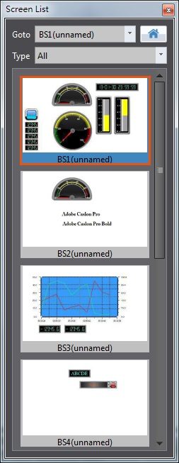
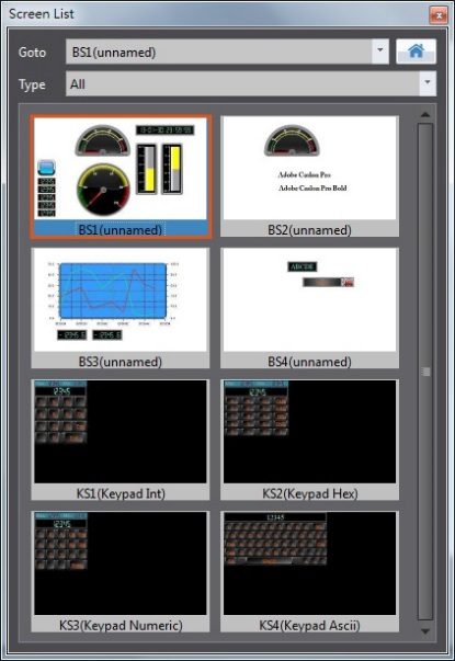
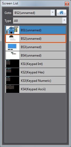
The【Screen List】is used to manage the HMI screens created by the user. The created HMI screens can be browsed here; selecting the screen with the left mouse button will open the screen in the work space. Pressing the right mouse button will open the management menu to perform further settings.
Refer to Chapter25.2-Screen List
The following figure is a screen of the Screen List:
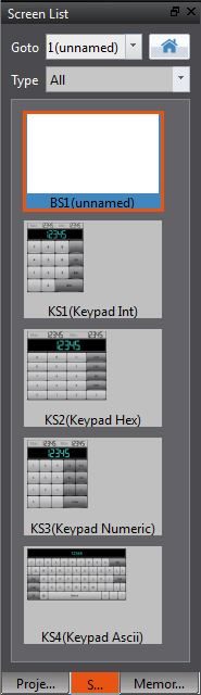
Figure 28 Screen List Interface
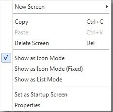
Figure 29 Management Menu
Table 10 Screen List Management Settings
|
Function |
Description |
|
【Goto】 |
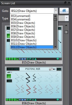
【Goto】provides two methods to select a screen to view. The first is through the drop-down menus on the right, choose to jump directly to the screen which you want to view, pictured below, after a screen is clicked, it will be displayed on the work space.
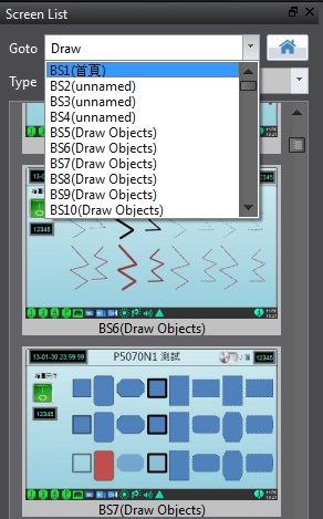
The second is through the search ID or the title of the screen, as shown in the following figure
|
|
【Startup screen】 |
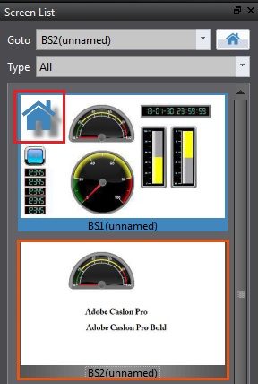
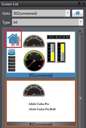
Provided to find 【Startup Screen】quickly, when the Startup Screen icon ( When the mouse is moved on the Screen List, the【Startup Screen】icon is displayed on the upper left corner of screen, this helps designers know which page is the【Startup Screen】.
|
|
【Type】 |
Contains All, Base Screen, Window Screen, Keypad Screen. Designers are able to choose which type of screen is displayed in the【Screen List】. |
|
【Current selection box】 |
The current selection box is an orange box in the list and displays the currently selected screen. See the following picture.
|
|
【New Screen】 |
Opens the screen property setting dialog; press OK to add the new screen (Base Screen/Window Screen/Keypad Screen). |
|
【Copy】 |
Copy the selected screen. |
|
【Paste】 |
Paste the copied screen. |
|
【Delete Screen】 |
Delete the selected screen, press the Ctrl button on the keyboard, choode multiple screens and delete them at one time on【Screen List】 |
|
【Show as Icon Mode】 |
The preview size will change according to the width of the window.
|
|
【Show as Icon Mode (Fixed)】 |
The preview size will not change according to the window width; the icons line up side by side to fill up the window size as much as possible.
|
|
【Show as List Mode】 |
The preview will be displayed as a list.
|
|
【Set as Startup Screen】 |
Set the selected screen as the startup screen. The background color of this screen will be different from other screens once it is set as the startup screen. |
|
【Properties】 |
Open the screen properties setting dialog.
|
 ) on the Screen List is pressed, it will move the current screen selection box to the【Startup Screen】and will display this【Startup Screen】on the Work Space.
2.7.2 Screen Properties
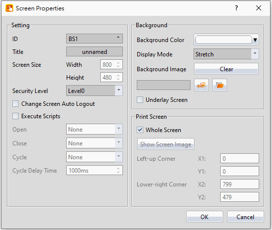
Screen properties opens a window that includes screen settings, background color and print screen. This window is accessible by right clicking the work space and selecting “Properties”. It is accessible on any screen.
The following figures display Properties screens:
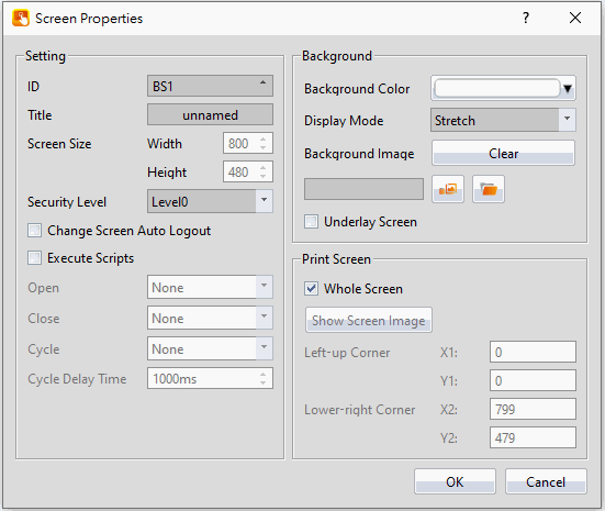
Figure 30 Base Screen Properties
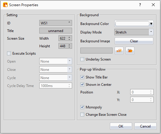
Figure 31 Window Screen Properties
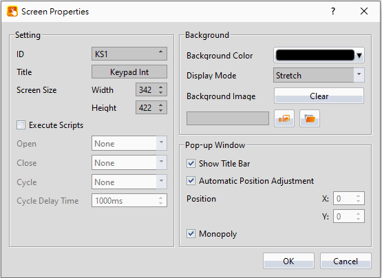
Figure 32 Keypad Screen Properties
Table 11 Screen Properties Items
|
Display Item |
Description |
|
【ID】 |
Work space ID. For base screens, the ID will begin with “BS” followed with a number. For window screens, the ID will begin with “WS” followed with a number. For keypad screens, the ID will begin with “KS” followed by a number. The arrows next to the text box allows a user to increment or decrement the number associated with the screen ID. |
|
【Title】 |
A screen caption for the current screen can be set. |
|
【Screen Size】 |
The screen and keypad screen height and width (in pixels) can be set. Note: the smallest width and height of window screen and keypad screen are 10. |
|
【Security Level】 |
A security level for the current screen can be set. The security level restricts users with a lower security level than the one set from accessing the current screen unless access is granted. |
|
【Change Screen Auto Logout】 |
Logs out the current user upon switching screens. |
|
【Execute Scripts】 |
Check the box to execute a script for the current screen. |
|
【Open】 |
Executes the selected script when the screen is opened. |
|
【Close】 |
Executes the selected script when the screen is closed. |
|
【Cycle】 |
Continuously executes the selected script. Cycle is based on the【Cycle Delay Time】. |
|
【Cycle Delay Time】 |
The delay in milliseconds between cycles of the script set in the【Cycle】option. |
|
【Background Color】 |
Set the color of the workspace background. |
|
【Display Mode】 |
Select the display mode, including strech, fixed percentage stretch, fill, or original size. |
|
【Background Image】 |
Use an image as the background. The buttons allow the user to either select an image from the Image library or from the computer. Acceptable image formats are .jpg, .jpeg, .bmp, .png, .tif, .tiff etc. |
|
【Underlay Screen】 |
Select the checkbox and select a screen to use as the underlaying screen from the dropdown menu. The underlay screen will reflect the selected screen. For example, if BS2 is selected as the underlay screen on BS1, all objects on BS2 will also be on BS1. However, those objects can only be changed on BS2. |
|
【Whole Screen】 |
Sets the range for printing as the entire screen. For example, the the HMI used is the P5070N, the resolution will be 800×480. |
|
【Show Screen Image】 |
Clicking this will open a window where the current screen will be shown. Adjusting X and Y coordinates will be reflected through the red rectangle on the screen image. |
|
【Left-up Corner】 |
Manually select the X and Y coordinates relative to the upper left corner. The red rectangle will adjust accordingly. |
|
【Lower-right Corner】 |
Manually select the X and Y coordinates relative to the bottom right corner. The red rectangle will adjust accordingly. |
|
【Show Title Bar】 |
Window screen or keypad screen can set whether show title bar when pop up screen window |
|
【Shown in Center】 |
Set to enable the window screen to show up in the center of the screen. |
|
【Automatic Position Adjustment】 |
Keypad screen can set whether the pop-up position is automatically adjusted. |
|
【Position】 |
Manually adjust the position of the window screen. This is enabled when the【Shown in Center】is not checked. |
|
【Monopoly】 |
If checked, objects outside the window screen or keypad screen cannot be accessed while the window screen is active. |
|
【Change Base Screen Close】 |
When the window screen switch to the basic screen, whether to retain the display of this window screen, if check this option window screen will automatically shut down. This option is only supported on Windows screen. |
2.7.3 Project Explorer
Project Explorer is the window to manage the entire project.
Table 12 Project Explorer Items
|
Function |
Description |
||||||||||||||||||||||
|
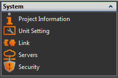
【System】 |
Please refer to Chapter 3–System for detailed contents. Related setting windows will appear on the work space when each button is pressed.
|
||||||||||||||||||||||
|
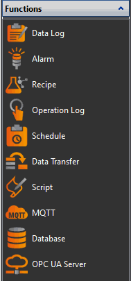
【Functions】 |
Related setting windows will be displayed on the work space when this button is pressed.
|
||||||||||||||||||||||
|
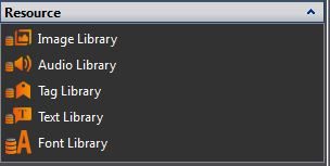
【Resource】 |
Please refer to【Resource】for detailed contents. The setting window will be displayed in the work space when each button is pressed. Refer to Chapter 18-Resourcefor detailed explanations.
|
2.7.4 Memory Address
External devices, internal HMI devices or HMI system variables usually need to be specified for the objects and functions of the HMI. It is difficult for a user to remember which resources are used for which objects or functions when there are many objects in a project; this is when【Memory Address】can be used to display which resources are used. This way, the user will be able to effectively plan the settings of any object or function in a project.
As shown in the figure below, red represents the device registers that are occupied, green represents that registers that are not yet used; the user can arrange and set resources through this function. Left-click an item in the list to use and the corresponding screen or function list menu will open; double clicking the left mouse button on the item will open the setting dialog of that item.
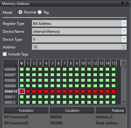
Figure 33 Normal mode memory address operation interface
In【Memory Address】, provides【Normal】and【Tag】two modes for searching.
In【Normal】mode, the grid map is used to indicate the memory usage of the current project. The grid map will be based on the currently selected【Register Type】,【Device Name】,【Device Type】and【Include Tag】.
In【Tag】mode, users can quickly find the usage of【Tag Library】tags.【Name】is the name of the tag created in the label library,【Location】displays the number of tags used, and【Address】is the address of the device register used by this tag.
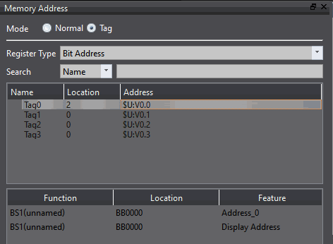
Figure 34 Tag mode memory address operation interface
After【Include Tag】is checked, the grid map will display the addresses used by tags in【Tag Library】.
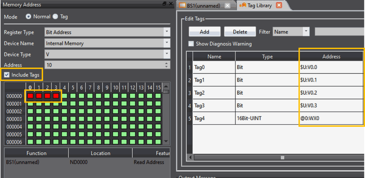
Figure 35 Memory address operation interface including tags
2.7.5 Output Message
When compiling, the output window will display the action status so that the developer can know about warnings, errors and other information after compilation is executed. Clicking the errors will open the related setting dialog directly for the user to debug.
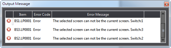
Figure 36 Output window
2.8 Object/Library Windows
2.8.1 Object List
This window lists all objects included on the screen; click the option in the window and the object in the【Work Space】will be highlighted (surrounded by a red frame), double clicking the mouse can display the editing window of the object directly.
There is a lock icon to the right of the【Object List】that can lock the function of the object; a locked object’s position and properties can be changed but cannot move the position. The eye icon controls the visibility of the object; when the icon is clicked into a closed eye, the object will not be displayed in the【Work Space】.
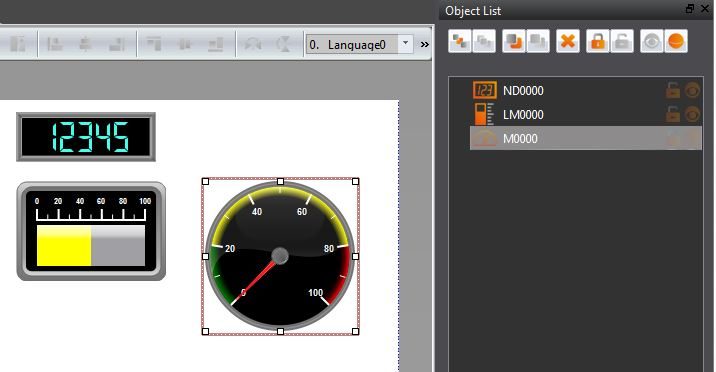
Figure 37 Object List
Table 13 Object List Functions
|
Function |
Description |
|
【Send to Back】 |
|
|
【Bring to Front】 |
|
|
【Move Backward】 |
|
|
【Move Forward】 |
|
|
【Delete Item】 |
|
|
【Lock Item/ Unlock Item】 |
|
|
【Show Item/ Hide Item】 |
|
|
【Object ID】 |
ID number of the object. Ex: LD_0001, LD is the model code, 0001 is the code number. |
 Send the selected object to the bottommost layer
 Bring the selected object to the topmost layer.
 Move the selected object down a layer.
 Move the selected object up a layer.
 will delete the selected object, press Ctrl can select multiple objects, deleted at one time.
 【Unlock】: Allow editing of the object properties or moving of the object.
 【Lock】: Disables editing of the object properties or moving of the object.
 【Visible】: Display object.
 【Invisible】: Hide object.
2.8.2 Toolbox
The FvDesigner provides a basic【Toolbox】; The developer can expand various types of objects provided directly from the toolbox according to the different categories. Select an object and drag it over to the【Work Space】with the mouse to insert the object into the work space.
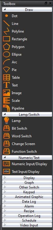
Figure 38 Toolbox Illustration
2.8.3 User Toolbox
Although the【Toolbox】provided by this software is able to meet the needs of most users, the objects provided in the【Toolbox】are all preset values and does not allow users to use custom objects. This is why this software also provides the【User Toolbox】function. In addition to allowing users to access objects that they have modified, it also provides【Import】and【Export】functions so that the objects in the 【User Toolbox】can be quickly transferred between different computers, speeding up project development.
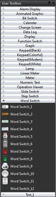
Figure 39 User Toolbox Illustration
2.9 Object/Library Windows
【Work Space】displays in two forms: The【Screen Edit Window】and【Function Settings Window】.
2.9.1 Screen Edit Window
Opening a window or adding a screen from the Screen List will display the Screen Edit Window in the work space. The【Status Bar】can be used to adjust the window display ratio and when an object is clicked,【Basic Setting】and【Status Bar】will display the position, size and other object alignment information. Use the functions on the design page to edit the objects in this window.【Toolbox】or objects in the【User Toolbox】can be added to the Screen Edit Window directly using drag-and-drop with the mouse.
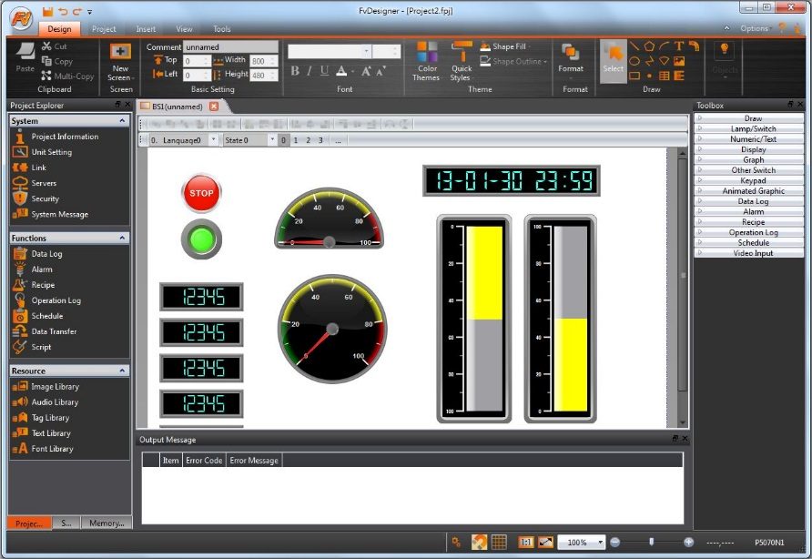
Figure 40 Work Space–Screen Edit
2.9.2 Function Settings Window
When a function setting to the left of the Project Explorer is clicked, for example when the operation log function option is clicked, the【Work Space】will display the operation log setting window as shown in the figure below. To close this window after setting is complete, click on the “x” (close) on the top of the screen.
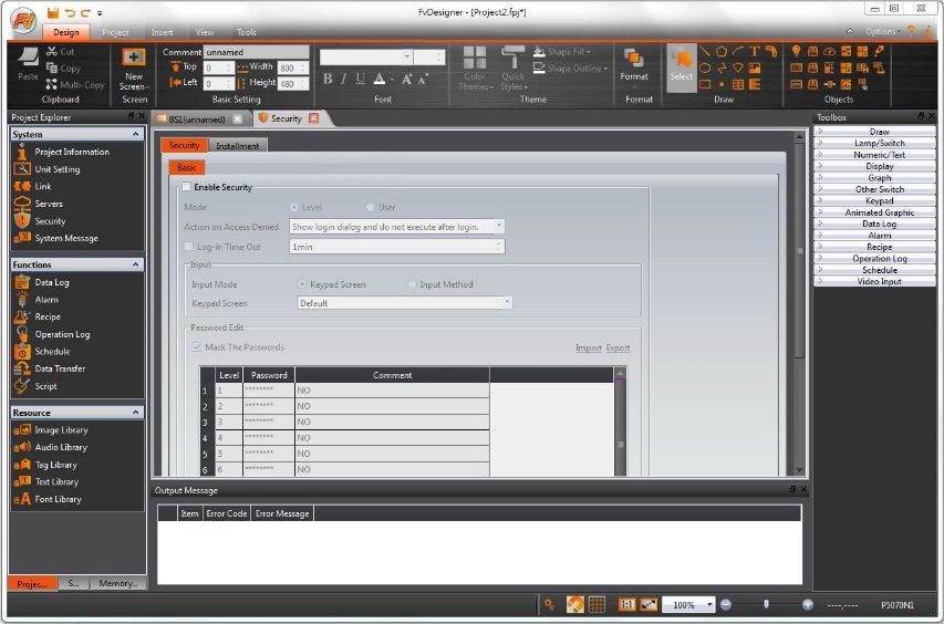
Figure 41 Work Space–Function Settings
Tip: press ← → to switch chapters, Ctrl+K to search