When the user needs to change the system settings of the HMI, such as IP, buzzer, and system time, users can enter to the【System Setting】to modify. The【System Setting】function can be used directly on the HMI, or can be modified remotely through the network connection with the【Remote System Setting】tool.
24.1 How To Enter System Setting
Press and hold down the right side of the screen during the HMI start-up process to enter the【System Setting】screen in order to change the system settings of the HMI.
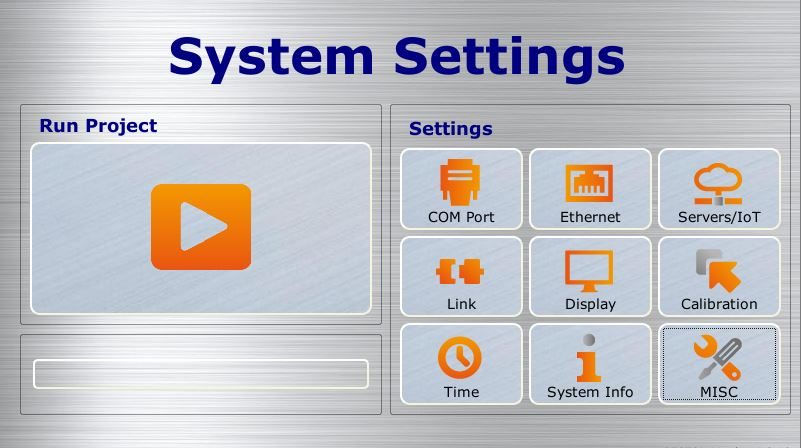
Figure 474 System Setting home page for HMI
24.2 【System Setting】Options
24.2.1 Run Project
The system will automatically detect the current firmware, integrity, and compatibility of the project on the HMI when entering the【System Setting】. If the system determines that the firmware and project versions are compatible and the file is complete with no corruptions, it will enable the【Run Project】and the user can execute the project on the HMI. If the system determines that the version is incompatible or that the file is corrupted, 【Run Project】will be locked, refer to chapter24.3-System Booting Sequence.
24.2.2 【COM Port】
The【COM Port】data page will appear after pressing the【COM Port】block, as shown in the figure below. This is where the COM Port details for the DB-9 male/terminal adapter of the HMI can be found. Pressing【OK】on the top-right corner or【Cancel】on the top-left corner will exit this page.
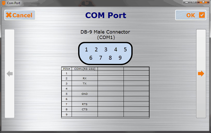
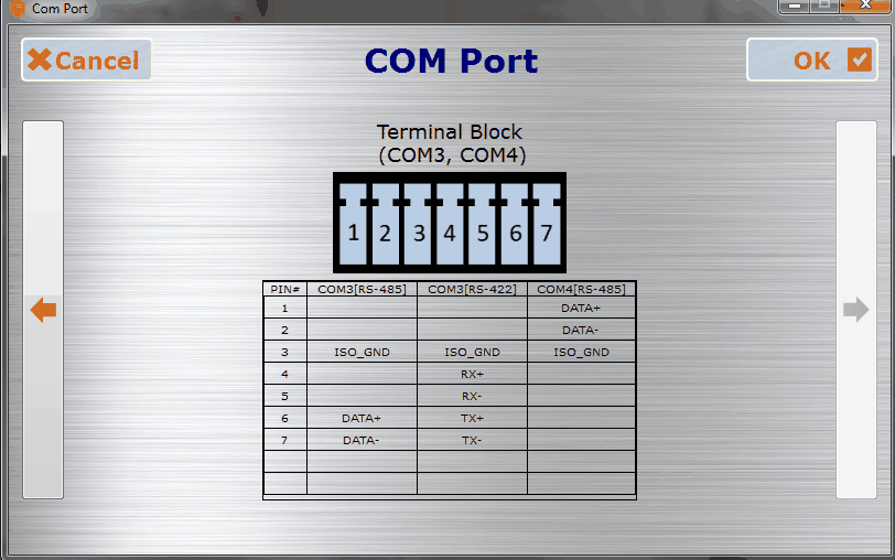
Figure 475 COM Port data page
24.2.3 【Network】
The【Network】settings will appear after pressing the【Network】block, the setting page is divided into【General】,【DNS】,【Access Control】, and【Wi-Fi】paging. When the setting is complete, press the【OK】button on the top-right corner to save the settings and exit this page or the【Cancel】button on the top-left corner to discard the changes and exit this page.
24.2.3.1 【Ethernet】
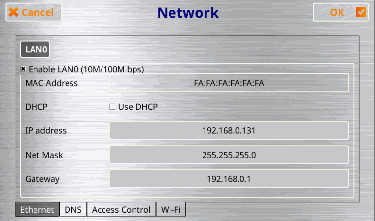
Figure 476【Network】【Ethernet】paging
Table 275【Network】【Ethernet】paging options
|
Option |
Description |
|
【Enable LAN0】 |
Select to enable【Network】: Selecting【Enable】will allow users to continue setting the follow-up options; selecting【Cancel】will close the follow-up options and they cannot be set. |
|
【MAC Address】 |
The MAC address of the HMI is displayed here. |
|
【DHCP】 |
Select whether to enable【Enable DHCP】. |
|
【IP Address】 |
Set the IP address of the HMI here. |
|
【Net Mask】 |
Set the sub-net mask of the HMI here. |
|
【Gateway】 |
Set the gateway of the HMI here. |
24.2.3.2 【DNS】
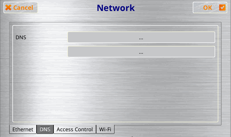
Figure 477【Network】【DNS】paging
Table 276【Network】【DNS】paging options
|
Option |
Description |
|
【DNS】 |
Can set 2 DNS settings |
24.2.3.3 【Access Control】
【Access Control】function can provide users to filter the connection IP or MAC address.
Note: This function only supports P5 series. The required operating system version is OS 2.0.13 or later.
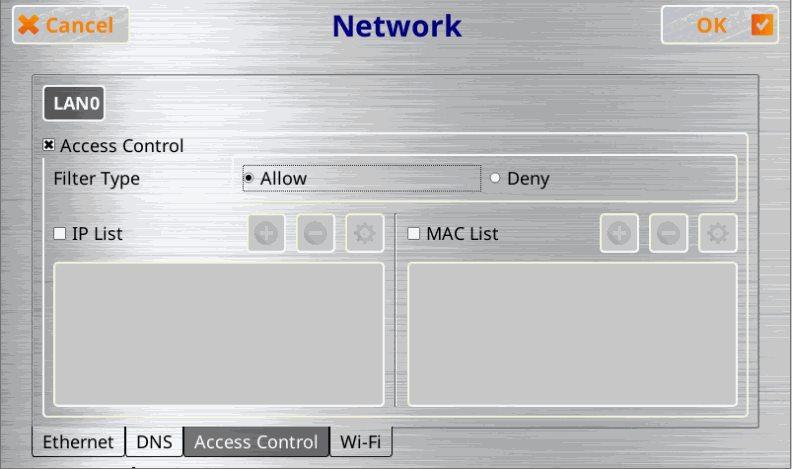
Figure 478【Network】【Access Control】paging
Table 277【Network】【Access Control】paging options
|
Option |
Description |
|
【Access】 |
Select whether to enable the【Access Control】function. |
|
【Filter Type】 |
Allow: Allow connection list Deny: Deny connection list |
|
【IP List】 |
Check to enable IP filtering list, up to 10 groups can be set. When adding an IP list, you will enter the【Filter Address】page. There are 3 rules to choose: 【Singal】: Enter a set of IP addresses to be filtered 【Subnet (CIDR Format)】: Enter a set of IP addresses and subnet mask to be filtered 【Range】: Enter two sets of IP, the IP within the range will be filtered |
|
【MAC List】 |
Check to enable MAC filtering list, up to 10 groups can be set. |
|
|
Add item |
|
|
Remove the selected item |
|
|
Modify the selected item |


24.2.3.4 【Wi-Fi】
HMI can use Wi-Fi Dongle for wireless Internet access, please notice that the HMI
Table 278 Wi-Fi Dongles support table
|
OS version:OS 2.0.14/ firmware version:1.5.74 or above are only supported |
OS version:OS 2.0.24/ firmware version:1.6.69 or above are only supported (update) |
|
D-Link DWA-182 |
D-Link DWA-171 |
|
TP-Link Archer T3U | AC1300 MU-MIMO |
D-Link DWA-185 |
|
ASUS USB-AC53NANO AC1200 |
MERCURY MW150US |
|
MERCURY MU6H |
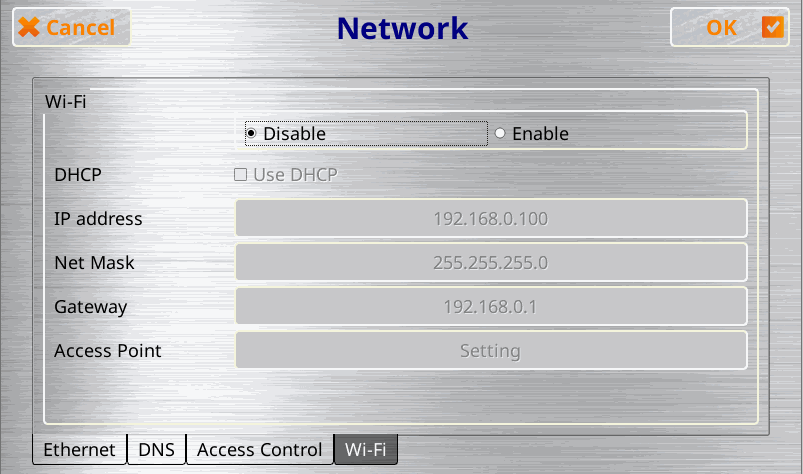
Figure 479【Network】【Wi-Fi】paging
Table 279【Network】【Wi-Fi】paging options
|
Option |
Description |
|
【Wi-Fi】 |
Select whether to enable the【Wi-Fi】function. |
|
【Access Point】 |
Select the access point to connect. |
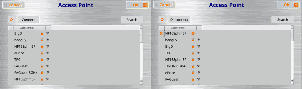
Figure 480【Wi-Fi】【Access Point】setting paging
Click the  icon to read the searched access point. The reading time takes a few seconds. After the searching is completed, you can select the access point to connect, click Connect and enter the password, or click Search to search the specified access point that it does not exist on the list, and when a checkmark
 appears in front of the access point, it means the connection is successful.
24.2.3.5 【4G Dongle】
HMI can use 4G SIM card for wireless Internet access, please note that HMI firmware version: 1.5.32 / OS version: OS 2.0.4 or above is supported
No special settings are required to use the 4G SIM card to access the Internet.
Only supports the model: D-Link DWM-222 (please contact us if you need it)
Hardware Spec: A1
Firmware Spec: V2.0.6
24.2.4 【Servers/IoT】
The【Servers/IoT】settings will appear after pressing the【Servers/IoT】block as shown in the figure below. The settings page are be divided into three paging:【Enable FTP Server】,【Enable VNC Server】,【Pass Through】,and【IoT】. When configuration is complete, press the【OK】button on the top-right corner to save the settings and exit this page or the【Cancel】button on the top-left corner to discard the changes and exit this page.
24.2.4.1 【FTP】
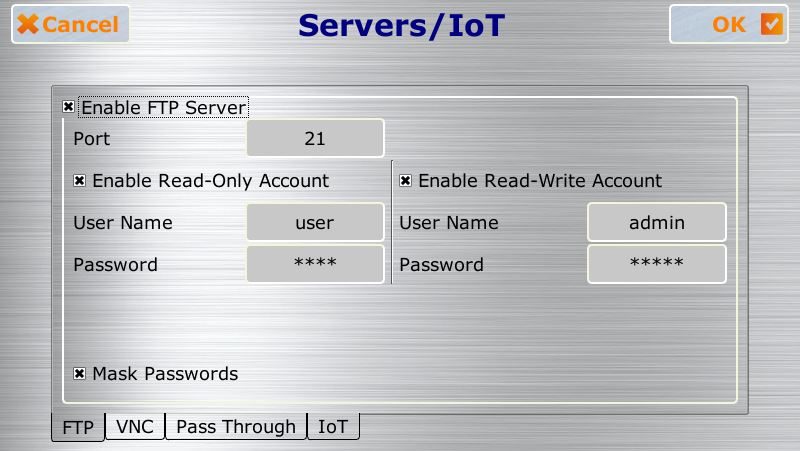
Figure 481【Servers/IoT Setting】【FTP】paging
Table 280 Options of【Servers/IoT Setting】【FTP】to Enable FTP Server in the Server page
|
Option |
Description |
|
【Enable FTP Server】 |
Select to【Enable FTP Server】. Selecting this option will allow users to continue setting the follow-up options. If this option is not selected, the follow-up options will be closed and cannot be set. Note: If the Enable FTP Server is selected, please remember to set【Read-Only Account】or【Read-Write Account】, or else the setting cannot be completed. |
|
【Port】 |
Select the port used by FTP Server. |
|
【Enable Read-Only Account】 |
Select to enable a read-only account. The user account and password can be set below once this option is selected. |
|
【Enable Read-Write Account】 |
Select to enable a read-write account. The user account and password can be set below once this option is selected. |
|
【Mask Password】 |
The password will be masked once this option is selected. |
24.2.4.2 【VNC】
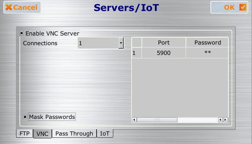
Figure 482【Servers/IoT Setting】【VNC】paging
Table 281 Options of【Servers/IoT Setting】【VNC】to Enable VNC Server in the Server page
|
Option |
Description |
|
【Enable VNC Server】 |
Select to【Enable VNC Server】. Selecting this option will allow users to continue setting the follow-up options. If this option is not selected, the follow-up options will be closed and cannot be set. |
|
【Connections】 |
Set how many VNC clients can be connected to this VNC server, the maximum number of support will vary depending on the model. |
|
【Mask Password】 |
The password will be masked if this option is selected. |
|
【Port】 |
Set the port of the VNC, only the first client’s port can be set, the second one will automatically increase, for example, the first one set 5900, then the second one will be 5901. |
|
【Password】 |
Enter the password for the VNC server. |
24.2.4.3 【Pass Through】
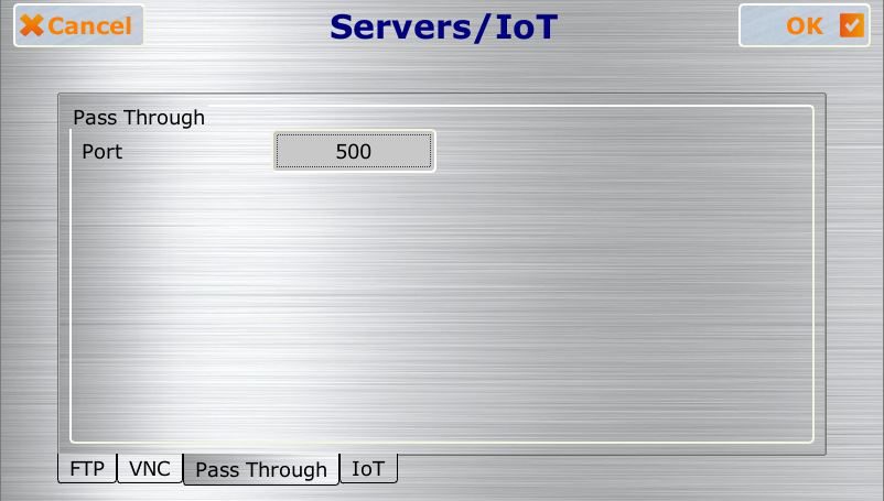
Figure 483【Servers/IoT Setting】【Pass Through】paging
Table 282【Servers/IoT Setting】【Pass Through】paging
|
Option |
Description |
|
【Pass Through Port】 |
Set the port used for pass through. |
24.2.4.4 【IoT】
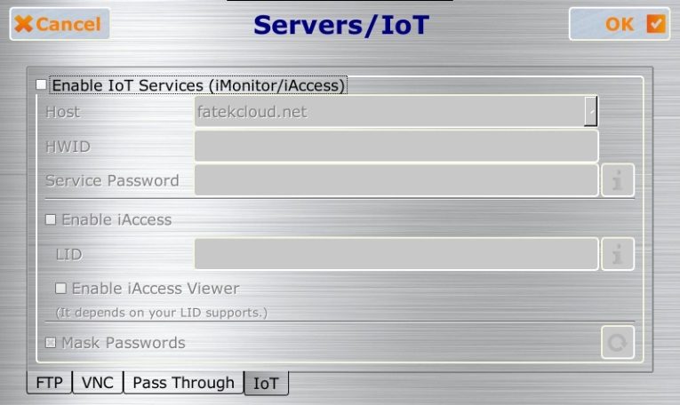
Figure 484【Servers/IoT Setting】【IoT】paging
Table 283【Servers/IoT Setting】【IoT】paging
|
Option |
Description |
|
【Enable IoT Services (iMonitor/iAceess)】 |
【Host】 Set the server to connect, including worldwild version(fatekcloud.net) and China version(fatekiot.cn). 【HWID】 HMI’s hardware ID, is unique and cannot be modified. 【Service Password】 When planning the IoT configuration on the IoT website, it needs this password to connected to HMI. |
|
【Enable iAceess】 |
【LID】 Key to activate the iAccess function. |
|
|
【Button Check】 After entering the【Service Password】or【LID】, press this button to connect to the server for validity verification. |
|
|
It will turn green after verification, and red if verification fails. Press the button behind【Service Password】, it will display check is valid or invalid Press the button behind【LID】to display whether the check is valid or invalid. If it is valid, it will display the available functions |


The cloud user manul can be download from the official website: http://www.fatek.com/zh-tw/download.php?act=list&cid=16
24.2.5 【Link】
The【Link】settings will appear after pressing the【Link】block, as shown in the figure below. Introductions to the options are as listed in the table below. When configuration is complete, press the【OK】button on the top-right corner to save the settings and exit this page or the【Cancel】button on the top-left corner to discard the changes and exit this page.
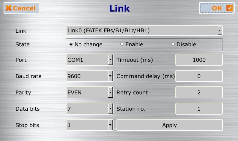
Figure 485【Link】setting page
Table 284【Link】setting page options
|
Option |
Description |
|
【Link】 |
Selet the link to modify. |
|
【State】 |
This option is only to control the link status, parameter setting is not included. 【No Change】 The latest link state will not change. 【Enable】 The link-state will be enabled(connecting) when running the project. 【Disable】 The link-state will be disabled(close) when running the project. |
|
【Apply】 |
After modifying each setting, you must press【Apply】and then【OK】a and【Execute Project】will record the modified content, if you only press OK, it will not be changed. |
Here only introduce the settings only in the HMI, other communication parameter please refer to chapter0-
Link.
24.2.6 【Display】
The【Display】settings will appear after pressing the【Display】block, as shown in the figure below. Introductions to the options are as listed in the table below. When configuration is complete, press the【OK】button on the top-right corner to save the settings and exit this page or the【Cancel】button on the top-left corner to discard the changes and exit this page.
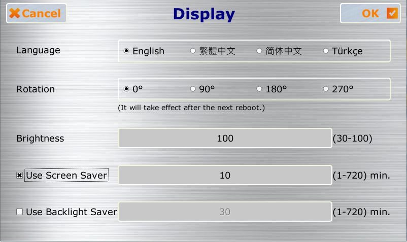
Figure 486【Display】setting page
Table 285【Display】setting page options
|
Option |
Description |
|
【Language】 |
Select the language displayed in【System Setting】. The available language selections is English, Traditional Chinese, Simplified Chinese, and Türkçe. |
|
【Rotation】 |
Select the rotation of the HMI display screen. Changes will take take effect after the system is rebooted. |
|
【Brightness】 |
Set the needed brightness, the selectable range is 30-100, and the default is 100. |
|
【Use Screen Saver】 |
Set whether to enable the screen saver, set the time if the function is enabled. |
|
【Use Backlight Saver】 |
Set whether to enable the backlight saver, set the time if the function is enabled. |
24.2.7 【Calibration】
The【Calibration】settings will appear after pressing the【Calibration】block. After entering the calibrations screen, follow the instructions to complete the calibration. Do not turn off the power before finishing the calibration.
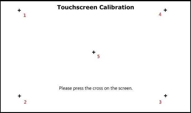
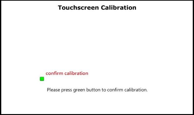
Figure 487【Calibration】page
There are 5 cross-calibration points. After pressing them in sequence, a green square will appear to confirm whether the calibration is successful. If failed for 3 times, you will need to do the calibration again.
If the error detected for the touch panel is too great resulting in users unable to properly click this【Calibration】block, users can then press and hold any point under the system setting page for ten seconds to enter the calibration mode.
24.2.8 【Time】
The【Time】settings will appear after pressing the【Time】block, as shown in the figure below. Introductions to the options are as listed in the table below. When configuration is complete, press the【OK】button on the top-right corner to save the settings and exit this page or the【Cancel】button on the top-left corner to discard the changes and exit this page.
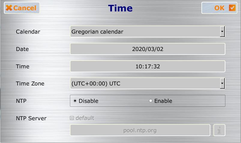
Figure 488【Time】setting page
Table 286【Time】setting page options
|
Option |
Description |
|
【Calender】 |
Select the calender of the HMI, includes Gregorain calender and Persian calender. |
|
【Date】 |
The system date of the HMI can be set here. |
|
【Time】 |
The system time of the HMI can be set here. |
|
【Time Zone】 |
The time zone of the HMI can be set here. After completing the settings, press 【OK】 in the upper right corner to save. Restart the device and wait 5 minutes for the time to update to the configured time zone. |
|
【NTP】 |
Here you can choose whether to enable network time synchronization (NTP time synchronization), enabling this feature requires setting time zone and DNS in order to effectively use. |
|
【NTP Server】 |
Users can connect to their own server or any other servers or the default server to synchronize the time. |
24.2.9 【System Info】
The【System Info】settings will appear after pressing the【System Info】block, as shown in the figure below. Introductions to the options are as listed in the table below. When configuration is complete, press the【OK】button on the top-right corner to save the settings and exit this page or the【Cancel】button on the top-left corner to discard the changes and exit this page.
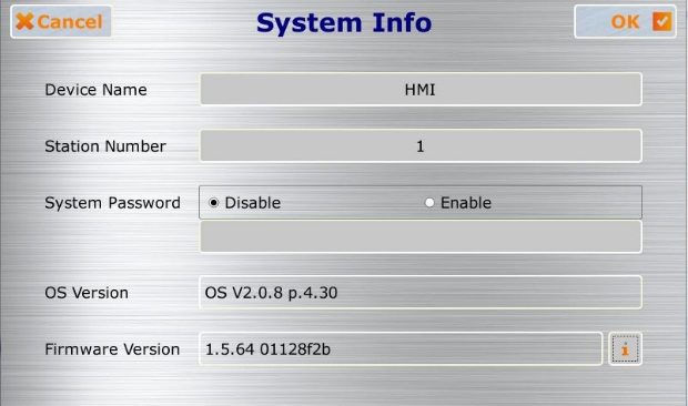
Figure 489【System Info】setting page
Table 287【System Info】setting page options
|
Option |
Description |
|
【Device Name】 |
The device name of the HMI can be set here. |
|
【Station Number】 |
The station number of the HMI can be set here. |
|
【System Password】 |
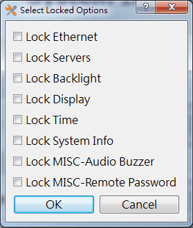
Select to enable【System Password】here. If【System Password】is enabled, the password must be set below. This password must be entered in order to set the locked option once【System Password】is enabled. Select the locked option, select the options which need enter【System Password】
|
|
【OS Version】 |
Information on the operating system version can be viewed here. |
|
【Firmware Version】 |
Information on the firmware version can be viewed here. |
|
【Last Update Time】 |
Display the last update time for the Project, Firmware, and Environment Package. |
24.2.10 【MISC】
The【MISC】settings will appear after pressing the【MISC】block, as shown in the figure below. Introductions to the options are as listed in the table below. When configuration is complete, press the【OK】button on the top-right corner to save the settings and exit this page or the【Cancel】button on the top-left corner to discard the changes and exit this page.
24.2.10.1 【General】
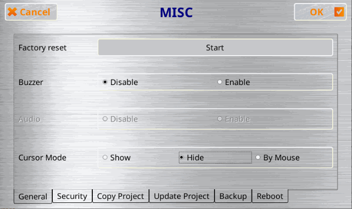
Figure 490【MISC】【General】setting page
Table 288【MISC】【General】settings page options
|
Option |
Description |
|
【Factory Reset】 |
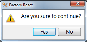
The system setting of the HMI can be re-set to the factory settings here. The following window will appear after this option is pressed, asking whether to continue.
Selecting【OK】will restore the HMI to factory settings and selecting【Cancel】will cancel this operation. |
|
【Buzzer】 |
This option enables the buzzer. Close will turn the buzzer off. |
|
【Audio】 |
Audio can be played back if this option is enabled, otherwise it will be closed. |
|
【Cursor Mode】 |
Here you can choose whether to display the cursor in the 【System Setting】screen. (Note: This function only supports display during system settings) 【Show】 Display cursor 【Hide】 Do not show the cursor 【According to the mouse】 The mouse will not be displayed without the mouse, and it will be displayed when the mouse is inserted. |
24.2.10.2 【Security】
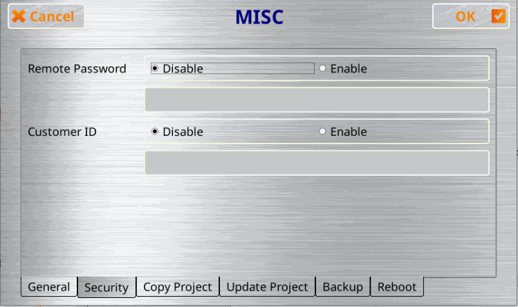
Figure 491【MISC】【Security】setting page
Table 289【MISC】【Security】settings page options
|
Option |
Description |
|||||||||
|
【Remote Password】 |
Set here whether to enable【Remote Password】, if you choose to enable【Remote Password】, you must continue to set the password below. After selecting enable 【Remote Password】,【Remote Setting】needs to enter【Remote Password】or【System Password】to enter【System Setting】. |
|||||||||
|
【Customer ID】 |
Set here whether to enable【Customer ID】. If you choose to enable【Customer ID】, you must continue to set the password below. When the project is executed, it will check whether the password set here is the same as the password of【Security】in【Project Information】. If they are the same, it will enter the customer planning project screen. If they are not the same, the HMI will stay on the boot screen and a prompt message indicating that the customer ID does not match will appear. At this time, the touch function, serial port, USB port and Ethernet port communication functions will be turned off. Cannot communicate with the PLC, and the customer cannot download through computer software. If the customer needs to download the project again, he must enter the HMI【System Setting】screen to download again.
For instructions on how to set the customer identification code in the project, please refer to the corresponding section 3.1.4-Project Security |
24.2.10.3 【Copy Project】
Before the connection, please follow chapter 2.2.2.5-Make USB Flash Drive Update File, put the generated .uferp under HMI Internal folder file through【File Transfer】.
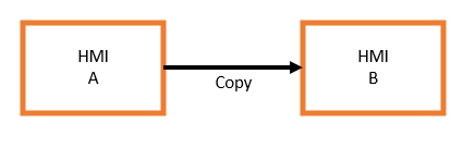
Figure 492【MISC】【Copy Project】schematic
Step
- The path to put the project’s USB update file (uferp) into the HMI A is: internal/Project.uferp
- Select the connection method from the system setting page of HMI A and press the start button
- Enter the project download password (if have) in HMI A
- Wait for the copying to complete, HMI B will update the project
Note 1: When generating the .uferp file, the ‘delete other’ option cannot select, otherwise the update will fail.
Note 2: The two HMI models must be the same to copy the project.
Note 3: The file name must be Project.uferp otherwise the system can’t find it.
Note4: If the download passwords of HMI A and HMI B are different, A will ask for the password; if they are the same, it will not be asked.
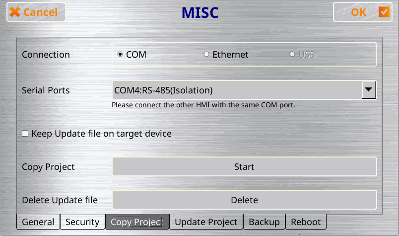
Figure 493【MISC】【Copy Project】setting page
Table 290【MISC】【Copy Project】settings page options
|
Option |
Description |
|
【Connection】 |
Select the connection way for the HMI to copy the project. |
|
【COM Port】 |
Select the COM port to use. |
|
【Keep Update file on target device】 |
Select whether to keep the .uferp file on the updated HMI. |
|
【Copy Project】 |
Press the button to start to copy the project. |
|
【Delete Update file】 |
Delete the .uferp file under the Internal folder. |
24.2.10.4 【Update Project】
User can update project without using computer.
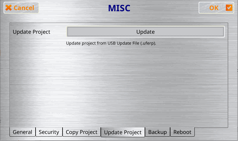
Figure 494【MISC】【Update Project】setting page
Table 291【MISC】【Copy Project】settings page options
|
Option |
Description |
|
【Update Project】 |
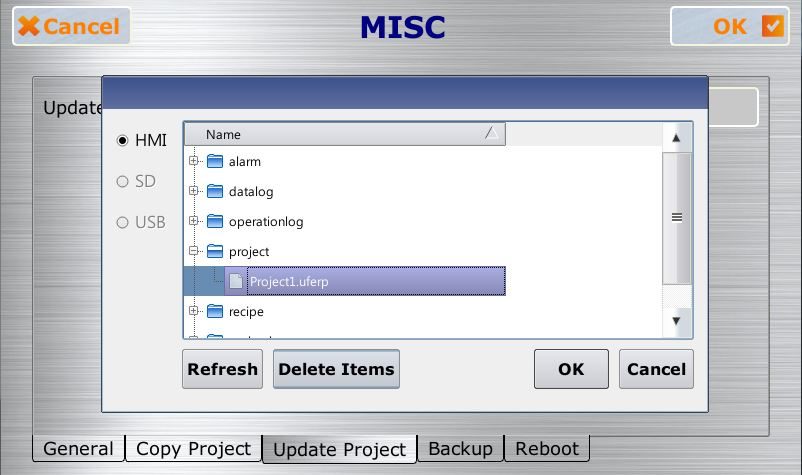
Update the .uferp file from HMI internal space, SD card, or USB flash disk.
|
24.2.10.5 【Backup】
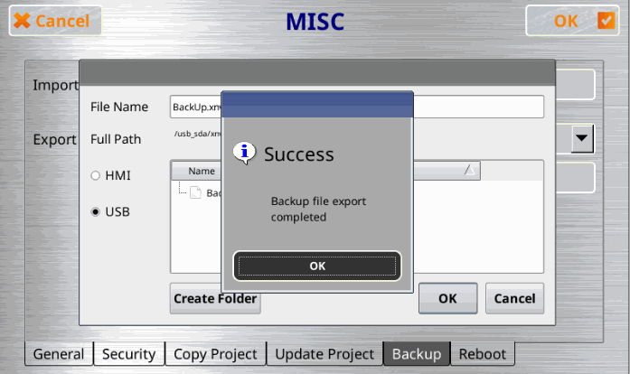
Backup the data that stores in the $U:XNV register into a package so that it can easily copy to another HMI.
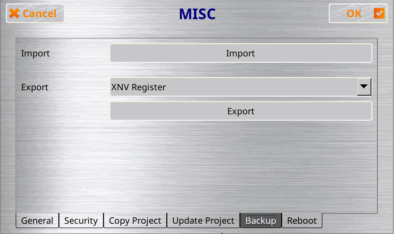
Figure 495【MISC】【Backup】setting page
Table 292【MISC】【Backup】settings page options
|
Option |
Description |
|
【$U:XNV register】 |
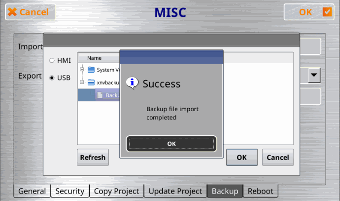
【Import】 Import the .xnv_backup file from the folder HMI/internal/xnvbackup.
【Export】 According to the HMI model and select the register type you want to export. The export .xnv_backup file will store under the folder HMI/internal/xnvbackup.
|
24.2.10.6 【Reboot】
Reboot the HMI.
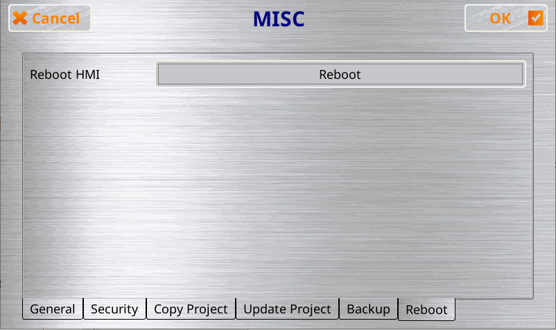
Figure 496【MISC】【Reboot】setting page
24.3 System Booting Sequence
The system will automatically detect the current firmware, integrity, and compatibility of the project on the HMI when starting up. If the system detected that the version is incompatible or that the file is corrupted resulting in the HMI being unable to start up properly, the system will automatically enter the【System Setting】and lock the【Run Project】switch. This is when users should use the download function of the FvDesigner to sequentially download the firmware and project.
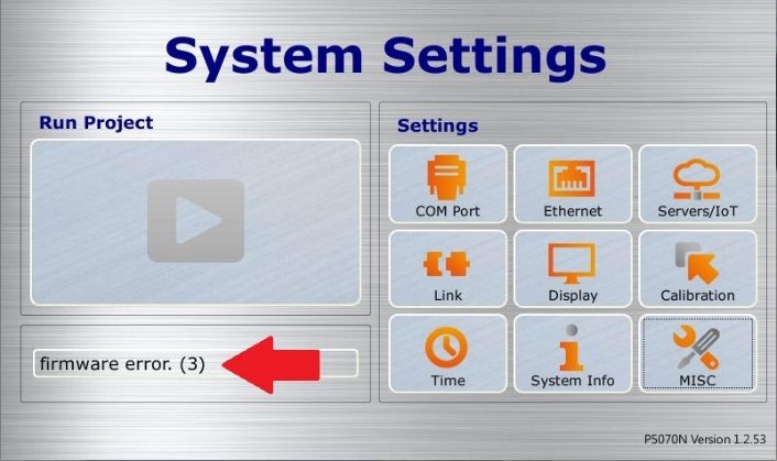
Figure 497 project error detection
If the firmware and project were both enabled normally, the system will skip the【System Setting】during start-up and run the project immediately. In this case, the user must press and hold the right side of the HMI screen during the start-up until it enters the System Setting screen if the user wants to adjust the system settings.
Tip: press ← → to switch chapters, Ctrl+K to search