【User-defined Protocol】function is the consulation mainly to provide the designer to connect the device according they need, define your own communication code, then communicate with the device, read or write to the device, generally can be used in simple communication connections,or in the case of a driver that is not currently supported in the software link. In addition, this【User-defined Protocol】function provide designers simple interface definition, no need to write a huge program, making it easier for designers to use, to achieve the purpose of communication with its equipment.
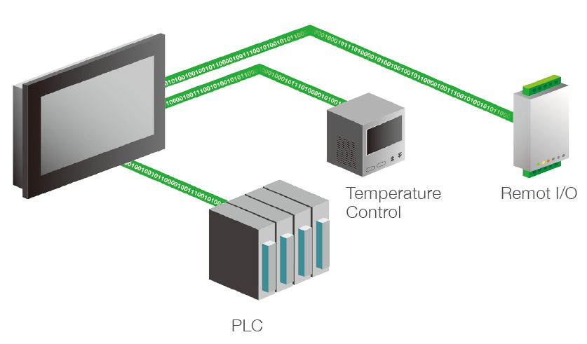
Figure 545 user-defined protocol illustration
28.1 【User-defined Protocol】Interface Description
This section describes the interface of the【User-defined Protocol】function that includes options and settings
【User-defined Protocol】function can add a link from【Project Explorer】【Link】, choose【User-defined Protocol】at【Manufacturer】, and choose【User-defined Protocol】at【Product Series】, as shown below.
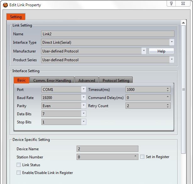
Figure 546 choose【User-defined protocol】
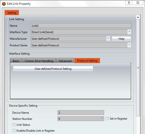
Figure 547 choose【Protocol Setting】
Then choose【User-defined Protocol Setting】, you can enter the instruction list set by User-defined Protocol Setting, as shown below, which set the meaning of the options, as shown in the table below.
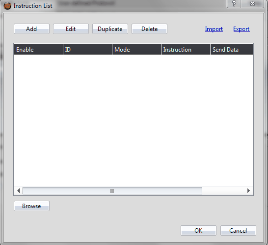
Figure 548【User-defined Protocol】instruction list
Table 305 properties of【User-defined Protocol】instruction list settings
|
Properties |
Description |
|
【Add】 |
Add a communication instruction |
|
【Edit】 |
Edit the communication instruction |
|
【Duplicate】 |
Duplicate the communication instruction |
|
【Delete】 |
Delete the communication instruction |
|
【Import】 |
Import all the instructions from CSV file |
|
【Export】 |
Export all the instructions to CSV file |
|
【Browse】 |
Display all the instructions in HEX |
|
【Enable】 |
You can select the enable instruction |
|
【ID】 |
ID number of ID |
|
【Mode】 |
Display instructions on read and write mode. |
|
【Instruction】 |
Display the contents of instructions |
|
【Send Data】 |
Display the instructions are read or write information |
|
【Return Info.】 |
Display information such as the return data address. |
28.1.1 Protocol Setting
Click【Add】can add a new communication instruction, enter the main edit interface of user-defined protocol, as shown below, each meaning of the setting, as the table shown below.
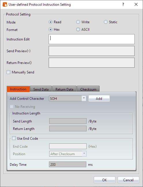
Figure 549【User-defined Protocol】main operation interface
Table 306 properties of【User-defined Protocol】main operation interface settings
|
Options |
Description |
|
【Mode】 |
【Read】means to read instruction 【Write】means to write instruction 【Static】to send a fixed content data, enabling this will force the activation of 【Manually Send】, When triggered, it will send static data. |
|
【Format】 |
You can choose【Hex】or【ASCII】two kinds of formats |
|
【Instrution Edit】 |
Edit the instruction you want to send. When the format is in HEX, can only enter 0-9/a-f/A-F, when you click on the other location in the screen will be automatically arranged into two numbers / letters for a group, and lowercase are converted into capital. If the format is ASCII, there is no such restriction. |
|
【Send Preview】 |
Preview window of sending instruction |
|
【Return Preview】 |
Preview window of returning instruction |
|
【Manually Send】 |
Manually send the instruction, the command will be sent when the Bit changes from off to on. |
28.1.2 Instruction
Below the 【User-defined Protocol Setting】dialog, you can choose【Instruction】paging, as shown belown, each meaning of the setting, as the table shown below.
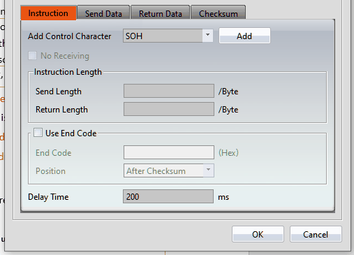
Figure 550【User-defined Protocol Setting】instruction paging
Table 307 properties of【User-defined Protocol Setting】instruction paging setting
|
Options |
Description |
|
【Add Control Character】 |
You can choose special character add into instruction edit dialog, |
|
【No Receiving】 |
Set whether or not to return the instructions, this function will appear when the mode set 【Write】. |
|
【Send Length】 |
Set the length of the return instruction request, in bytes. |
|
【Return Length】 |
Set the length of the received return data. Reception of the end code will stop the reception of return messages. |
|
【Use End Code】 |
Checking this option means using the end code to determine the end position of the return message. Once checked, 【Return Length】will change to 【Max Return Length】. If the termination character is not received, the reception will stop at the length set in this field. 【End code】the end code to be used, must be filled in hexadecimal format, for example, 0D 0A. 【Position】the selected end code will force the checksum position to be set to the end. The sequence of checksum and termination character settings is as follows: 【After Checksum】reception of the return message stops upon receiving the end code, and the remaining message is not received. 【Before Checksum】after receiving the end code of the return message, a checksum will be received, and the remaining message is not received. |
|
【Delay Time】 |
After sending the set of instruction, delay how many times to send the next instruction, the amount of reading and writing will affect this time. |
28.1.3 Send Data
Below the 【User-defined Protocol Setting】dialog, you can choose【Send Data】paging, as shown belown, each meaning of the setting, as the table shown below.
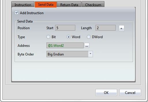
Figure 551【User-defined Protocol Setting】send data paging
Table 308 properties of【User-defined Protocol Setting】send data paging setting
|
Options |
Description |
||||||||||||||||||
|
【Add Instruction】 |
When【Mode】choose in【Read】, it can be checked. Let the user set the command to variable. |
||||||||||||||||||
|
【Position】 |
It can set the position of sending data in the sending instruction, and set it through【Start】and【Length】, for easy to use, you also can set start position and length |
||||||||||||||||||
|
【Type】 |
Set the type of writing, including bit, word, double word. |
||||||||||||||||||
|
【Address】 |
When【Mode】is【Read】or【Write】, the command sent includes the storage address of the variable. When【Manually Send】 is not checked, it will be sent according to the 【Delay Time】. When 【Manually Send】 is checked and the Bit is On, data will only be sent when there is a change. When【Mode】is【Static】or【Write】, this function annot be used here. Note : PLC addresses cannot be used here; only internal HMI addresses or addresses specific to the driver can be used. |
||||||||||||||||||
|
【Byte Order】 |
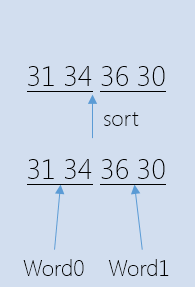
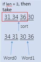
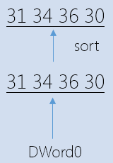
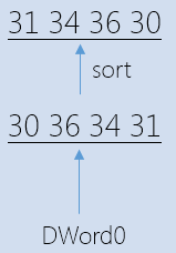
【Bit】 When【Type】is【Bit】,
【Byte Order】 When【Type】is【Word】or【DWord】, can choose【Big Endian】or【Little Endian】to sort.
|
||||||||||||||||||
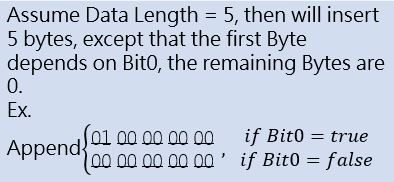
28.1.4 Return Data
Below the【User-defined Protocol Setting】dialog you can choose【Return Data】paging, as shown belown, each meaning of the setting, as the table shown below.
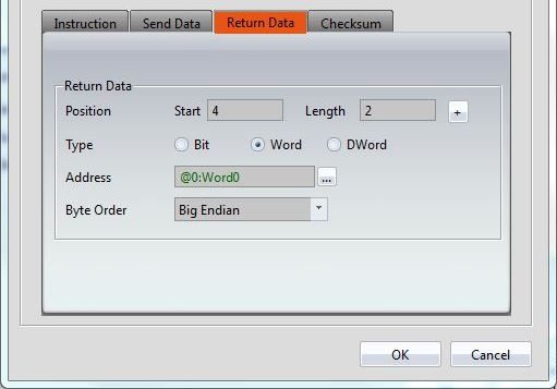
Figure 552【User-defined Protocol Setting】returndata paging
Table 309 properties of【User-defined Protocol Setting】return data paging setting
|
Option |
Description |
||||||||||||||||||||
|
【Position】 |
Set the position of the received return data within the command using 【Start】and 【Length】. In the 【Instruction】, you need to set the 【Return Length】. |
||||||||||||||||||||
|
【Type】 |
Set the type of store, include bit, word, double word |
||||||||||||||||||||
|
【Address】 |
When【Mode】is【Read】or【Write】, the command sent includes the storage address of the variable. When【Mode】is【Static】or【Write】, this function annot be used here. Note : PLC addresses cannot be used here; only internal HMI addresses or addresses specific to the driver can be used. |
||||||||||||||||||||
|
【Byte Order】 |
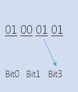
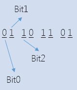
【Bit】 When【Type】is【Bit】,
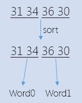
【Byte Order】 When【Type】is【Word】or【DWord】, can choose【Big Endian】or【Little Endian】to sort. Difference shown as below
|
||||||||||||||||||||
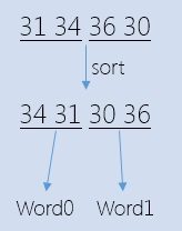
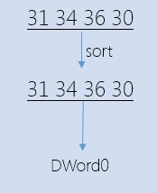
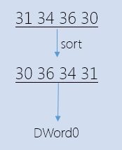
28.1.5 Checksum
Below the【User-defined Protocol Setting】dialog, you can choose【Checksum】paging, as shown belown, each meaning of the setting, as the table shown below.
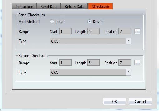
Figure 553【User-defined Protocol Setting】checksum paging
Table 310 properties of【User-defined Protocol Setting】checksum paging setting
|
Option |
Description |
|
【Checksum】 |
Provides an automatic calculation of the checksum. |
|
【Send Checksum】 |
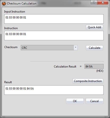
Under add method of【Send Instruction】, provides【Local】and【Driver】two methods. 【Local】 When choose【Local】, indicates that the checksum needs to be entered manually in the 【Send Instruction】, the following will have a 【Setting】 option to facilitate the use of designers to calculate. 【Setting】 It will appear【Check Calculation】dialog after click setting, as shown below
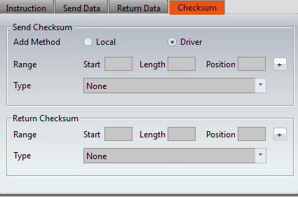
【Input Instruction】 Data of the【Instruction Edit】on the main operation interface. 【Quick Add】 Click the botton then will copy the value form【Input Instruction】to the【Instruction】field 【Instruction】 An instruction of using to calculate checksum 【Checksum】 The way to calculate checksum, includes none, CRC, SUM(BYTE), SUM(WORD), XOR, AND, OR, LRC, SUM Complement, SUM Radix-Minus-One Complement, etc. 【Calculate】 Calculate checksum,the results will display on【Calculate Result】。 【Calculate Result】 Except LRC, other instructions converted to HEX format to be calculated. 【Composite Instruction】 Combine the calculation result and the origin instruction, the value will show up in【Result】 【OK】 Store the value of【Result】to the data of the main operation interface【Instruction Edit】 【Cancel】 Leave this dialog, it won’t change anything. 【Driver】 When choose【Driver】, indicates that the checksum will be automactically calculated and generated by the driver, the system will calculate checksum from【Start】, bytes of【Length】checksum, and insert it into【Position】,as shown below.
【Range】 set the range of checksum calculation. 【Start】 Set the position where the checksum starts to calculate 【Length】 Set the length of the checksum calculation, in bytes 【Position】 Set the position where the checksum calculation result is inserted 【Automatically fill in】 For easy to use, you can also select the starting position and length in the【Send Preview】window, when you press the【+】button next to【Length】, you can fill in the 【Start】 and 【Length】 fields automatically. 【Type】 Choose the type of checksum calculation, includes none, CRC, SUM(BYTE), SUM(WORD), XOR, AND, OR, LRC, SUM Complement, SUM Radix-Minus-One Complement, etc. |
|
【Return Checksum】 |
When it has return instruction, you can set whether to verify the return data in the checksum. 【Range】 set the range of checksum calculation. 【Start】 Set the position where the checksum starts to calculate. 【Length】 Set the length of the checksum calculation, in bytes. 【Position】 Set the position where the checksum calculation result is inserted 【Automatically fill in】 For easy to use, you can also select the starting position and length in the【Return Preview】window, when you press the【+】button next to【Length】, you can fill in the【Start】and【Length】fields automatically. 【Type】 Choose the type of checksum calculation, includes none, CRC, SUM(BYTE), SUM(WORD), XOR, AND, OR, LRC, SUM Complement, SUM Radix-Minus-One Complement, etc. |
28.2 【User-defined Protocol】Application examples
This section explains how to apply the【User-defined Protocol】function.
28.2.1 Establishing a Connection
First, create a connection under 【Link】, selecting【User-defined Protocol】for the manufacturer and product series. Ensure that the parameter settings match the communication device interface.
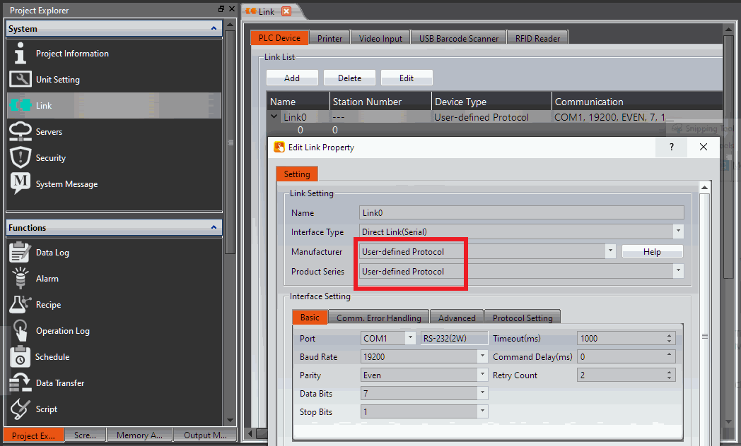
Figure 554 Set up Link
Switch to the【Protocol Setting】tab and click【User-defined Protocol Setting】to open the【Instruction List】.
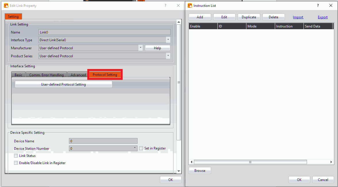
Figure 555 Switch to Instruction List Page
28.2.2 Editing Commands
This example demonstrates using HMI to communicate with an FBs-PLC through commands. In the【Instruction List】, click Add and configure as follows:
本次範例使用HMI與FBs-PLC使用指令方式通訊,在【指令列表】中點選新增,並依下圖設定
- Instruction Content : 02 30 31 34 36 30 31 52 30 30 30 30 30 37 30 03
- Remain the「Send Data」and「Checksum」tabs unchanged.
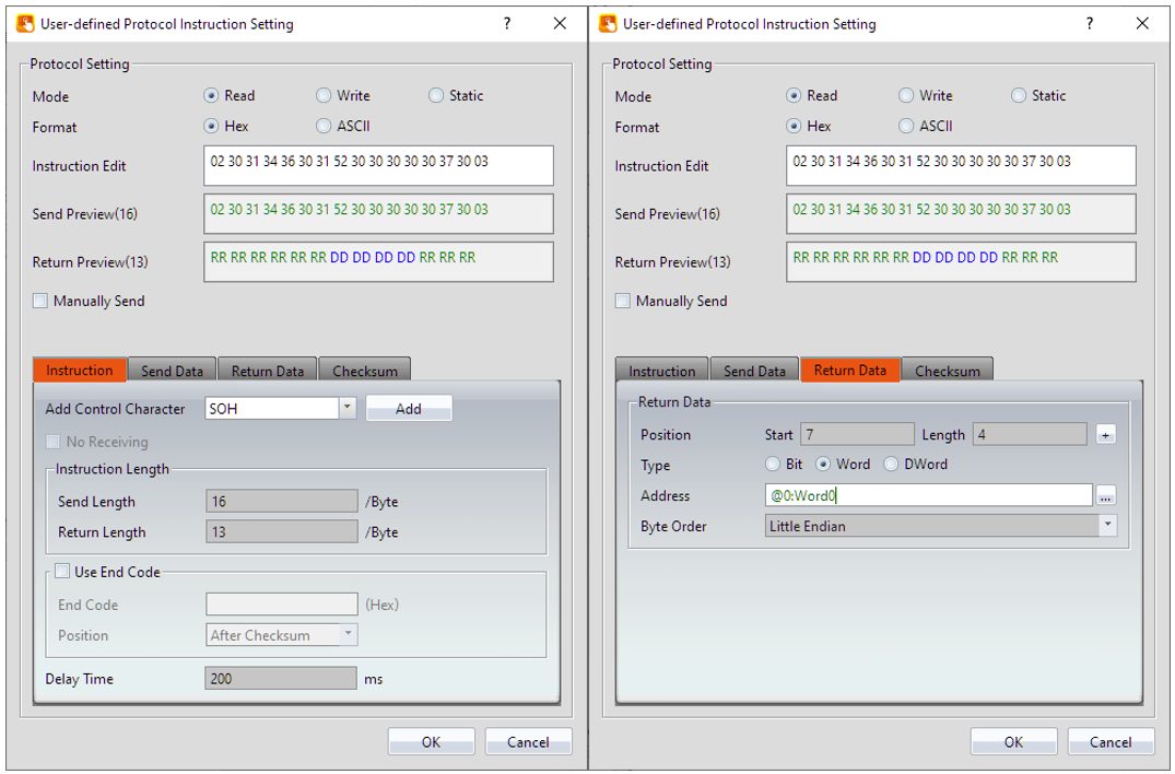
Figure 556 Edit Command Content
The command content explanation below should refer to the communication manual of the specific device.
This is the FBs communication command:
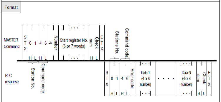
Transmission Code Explanation
|
02 |
30 31 |
34 36 |
30 31 |
52 |
30 30 30 30 30 |
37 30 |
03 |
|
STX |
Station No. |
Command code |
Data length |
R |
0 |
Checksum |
ETX |
The return command is as follows:
|
RR |
RR RR |
RR RR |
RR |
DD DD DD DD |
RR RR |
RR |
|
STX |
Station No. |
Command code |
Error code |
Data |
Checksum |
ETX |
Set the return length to 13,
with the return data starting at position 7 and a length of 4.
Based on the command explanation above, this user-defined communication protocol action reads the value of R0.
28.2.3 Reading Values
After editing the command, go back to the project screen and add a display. Set the monitoring address to the address specified in the user-defined communication protocol. Once the project is downloaded, the values can be read.
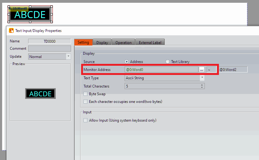
Figure 557 Display Setup
28.3 【User-defined Protocol】use Script Application Example
This section explains how to use the【User-defined Protocol】function of the script, communicate with the Modbus device, and read the data of Modbus address, for example, HMI connect with FATEK FBs PLC through COM1, then connect with Modbus device of station number 1 through COM4 by using user-defined protocol, read the data of address 40001 through the script, as shown below.
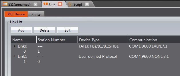
Figure 558 HMI COM1 and COM4 connection page
28.3.1 Communication Instructions in Script
Use the function【User-defined Protocol】in script, will mainly use the【io write and read】and【Checksum】instruction, as shown below, each meaning of the setting as shown below, as the table below.
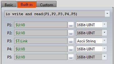
Figure 559 communication instruction in script
Table 311 properties of communication instruction in script settings
|
Options |
Io write and read insruction description |
|
【P1】 |
The start address to send instruction. |
|
【P2】 |
Send the length of the instruction. |
|
【P3】 |
Device name. |
|
【P4】 |
The start address to return instruction. |
|
【P5】 |
Return the length of the instruction. |
|
Options |
Checksum instrunction description |
||||||||||||||||||||||
|
【P1】 |
Calculation method.
|
||||||||||||||||||||||
|
【P2】 |
Calculate start address. |
||||||||||||||||||||||
|
【P3】 |
Calculate words. |
||||||||||||||||||||||
|
【P4】 |
Result store start address, starting with 1 or 2 consecutive words, depending on the calculation method |
||||||||||||||||||||||
28.3.2 Communication Instruction in Script Application Example
Read the data of address 40001 of Modbus device through script, setting steps as follow.
Step 1: Build a new project and build link 0, select Fatek FBs/B1/B1z/HB1 driver, build link 1, select【User-define Protocol】driver, about the communication parameter settings are same as Modbus device, please refer to other relevant sections for this section.
Step 2: Build 2 tags at Tag library, as shown below.
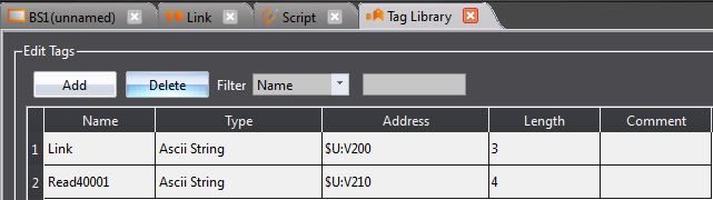
Figure 560 communication instruction in script
Step 3: Write script, as shown below.
- First row specifies the name of the device to be read
- Second row is to set the instruction to be send.
- Third row is to turn ASCII string into INT
- Fourth row is to calculate checksum
- Fifth row is to copy the checksum to send instruction
- Sixth row is to copy the checksum to send instruction
- Seventh row is to excute io_write_and_read instruction, send out the send instruction, and read the return data stored in $ U: V240 start of the seven consecutive addresses
- eighth to eleventh rows are convert read back data and store it in $ U: V300
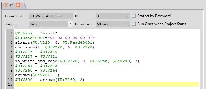
Figure 561 Read the 40001 address data script for the Modbus device
Step 4: Planning a new【Numeric Input/Display】object,【Monitor Adderss】set as $U:V300, as shown below, you can read the station number 1 Modbus device 40001 address value.
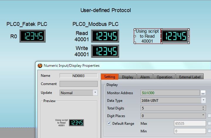
Figure 562 Planning a new【Numeric Input/Display】object
Tip: press ← → to switch chapters, Ctrl+K to search