10.1 List of Parameters
10.1.1 Interpreting the Parameter Lists
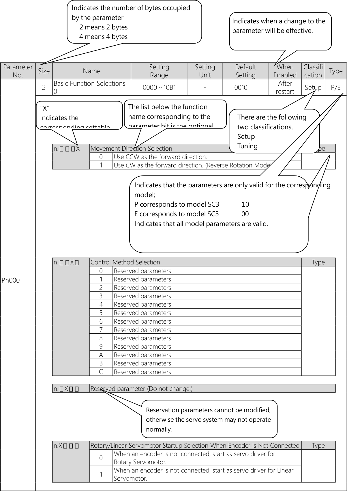
10.1.2 List of Parameters
The following table lists the parameters.
NOTE: Do not change the following parameters from their default settings.
• Reserved parameters
• Parameters not given in this manual
|
Parameter No. |
Size |
Name |
Setting Range |
Setting Unit |
Default Setting |
When |
Classific ation |
Type |
||||||||||||||||||||||||||||||||||||||||||||||||||||||||
|
Pn000 |
2 |
Basic Function Selections 0 |
0000~10B1 |
– |
0000 |
After restart |
Setup |
– |
||||||||||||||||||||||||||||||||||||||||||||||||||||||||
|
||||||||||||||||||||||||||||||||||||||||||||||||||||||||||||||||
|
Pn001 |
|
0000~1142 |
– |
0000 |
After restart |
Setup |
– |
|||||||||||||||||||||||||||||||||||||||||||||||||||||||||
|
||||||||||||||||||||||||||||||||||||||||||||||||||||||||||||||||
|
||||||||||||||||||||||
|
Parameter No. |
Size |
Name |
Setting Range |
Setting Unit |
Default Setting |
When |
Classific ation |
Type |
|||||||||||||||||||||||||||||||||||||||||||||||||||||
|
Pn002 |
2 |
Application Function Selections 2 |
0000~4213 |
– |
0000 |
After |
Setup |
P |
|||||||||||||||||||||||||||||||||||||||||||||||||||||
|
0011 |
E |
||||||||||||||||||||||||||||||||||||||||||||||||||||||||||||
|
|||||||||||||||||||||||||||||||||||||||||||||||||||||||||||||
|
Pn008 |
|
0000~7121 |
– |
4000 |
After restart |
Setup |
|||||||||||||||||||||||||||||||||||||||||||||||||||||||
|
|||||||||||||||||||||||||||||||||||||||||||||||||||||||||||||
|
Pn009 |
2 |
Application Function Selections 9 |
0000~0121 |
– |
0010 |
After restart |
Tuning |
– |
||||||||||||||||||||||||||||
|
||||||||||||||||||||||||||||||||||||
|
Parameter No. |
Size |
Name |
Setting Range |
Setting Unit |
Default Setting |
When Enabled |
Classific ation |
Type |
|||||||||||||||||||||||||||||||||||||||||||||||||||||
|
Pn00A |
2 |
Application Function Selections A |
0000~0044 |
– |
0001 |
After restart |
Setup |
– |
|||||||||||||||||||||||||||||||||||||||||||||||||||||
|
|||||||||||||||||||||||||||||||||||||||||||||||||||||||||||||
|
Pn00B |
2 |
Application Function Selections B |
0000~1121 |
– |
0000 |
After restart |
Setup |
– |
|||||||||||||||||||||||||||||||||||||||||||||||||||||
|
|
r Para
oppin
|
meter Display Selection Display only setup parameters. Display all parameters. g Method for Group 2 A the motor by setting the y the dynamic brake or c ing method set in Pn00 he stopping method with |
s. larms |
nce to 0. or to a stop (us X. |
|
|
||||||||||||||||||||||||||||||||||||||||||||||||||||||
|
n.▯X▯▯ |
Power In |
put S |
election for Three-phase |
servo driver |
Type |
||||||||||||||||||||||||||||||||||||||||||||||||||||||||
|
0 |
Use a |
three-phase power sup |
ply input. |
– |
|||||||||||||||||||||||||||||||||||||||||||||||||||||||||
|
1 |
Use a three-phase power supply input as a single-phase power supply input. |
|||||||||
|
n.X▯▯▯ |
Reserved parameter (Do not change.) |
|||||||||
|
2 |
Application Function |
0000~1001 |
– |
0000 |
After |
Setup |
– |
|||
|
Selections D |
restart |
|||||||||
|
n.▯▯▯X |
Reserved parameter (Do not change.) |
|||||||||
|
n.▯▯X▯ |
Reserved parameter (Do not change.) |
|||||||||
|
Pn00D |
n.▯X▯▯ |
Reserved parameter (Do not change.) |
||||||||
|
n.X▯▯▯ |
Overtravel Warning Detection Selection |
|||||||||
|
0 |
Do not detect overtravel warnings. |
|||||||||
|
1 |
Detect overtravel warnings. |
|||||||||
|
2 |
Application Function |
0000~2011 |
– |
0000 |
After |
Setup |
– |
|||
|
Selections F |
restart |
|||||||||
|
n.▯▯▯X |
Preventative Maintenance Warning Selection |
|||||||||
|
0 |
Do not detect preventative maintenance warnings. |
|||||||||
|
1 |
Detect preventative maintenance warnings. |
|||||||||
|
Pn00F |
n.▯▯X▯ |
Reserved parameter (Do not change.) |
||||||||
|
n.▯X▯▯ |
Reserved parameter (Do not change.) |
|||||||||
|
n.X▯▯ |
Reserved parameter (Do not change.) |
|||||||||
|
▯ |
|||||||||||
|
Parameter |
Size |
Name |
Setting Range |
Setting UnitDefault Setting |
When |
Classific |
Type |
||||
|
No. |
Enabled |
ation |
|||||||||
|
Pn010 |
2 |
Axis Address Selection |
1~ 127 |
– |
1 |
After |
Setup |
– |
|||
|
(USB) |
restart |
||||||||||
|
2 |
UART/CAN |
After |
Setup |
P |
|||||||
|
Communication |
0000~1643 |
– |
0401 |
||||||||
|
restart |
|||||||||||
|
parameter selection switch |
|||||||||||
|
Selecting UART serial communication rate |
Type |
|||||||||
|
0 |
9600 bps |
||||||||||
|
1 |
19200 bps |
||||||||||
|
2 |
38400 bps |
– |
|||||||||
|
3 |
57600 bps |
||||||||||
|
Pn011 |
4 |
115200 bps |
|||||||||
|
Selecting UART serial comminication parity check and stop bit |
Type |
|||||||||
|
0 |
No Parity ,1 Stop Bit |
||||||||||
|
1 |
Even Parity ,1 Stop Bit |
– |
|||||||||
|
2 |
Odd Parity ,1 Stop Bit |
||||||||||
|
n.▯X▯▯ |
Reserved parameter (Do not change.) |
Type |
|||||||||
|
n.X▯▯▯ |
Reserved parameter (Do not change.) |
Type |
|||||||||
|
Pn013 |
2 |
EtherCAT station number |
After |
Setup |
E |
||||||
|
selection (for ECAT |
0000〜FFFF |
– |
0001 |
||||||||
|
restart |
|||||||||||
|
communication) |
|||||||||||
|
Parameter No. |
Size |
Name |
Setting Range |
Setting Unit |
Defau lt |
When |
Classification |
Type |
|||||||||||||||||||||||||||||||||||||||||||||
|
Pn080 |
2 |
Application Function Selections 80 |
0000~1111 |
– |
0000 |
After restart |
Setup |
E |
|||||||||||||||||||||||||||||||||||||||||||||
|
|||||||||||||||||||||||||||||||||||||||||||||||||||||
|
Pn100 |
2 |
Speed Loop Gain |
10~20000 |
0.1 Hz |
400 |
Immediately |
Tuning |
||||||||||||||||||||||||||||||||||||||||||||||
|
Pn101 |
2 |
Speed Loop Integral Time Constant |
15~51200 |
0.01 ms |
2000 |
Immediately |
Tuning |
||||||||||||||||||||||||||||||||||||||||||||||
|
Pn102 |
2 |
Position Loop Gain |
10~20000 |
0.1/s |
400 |
Immediately |
Tuning |
||||||||||||||||||||||||||||||||||||||||||||||
|
Pn103 |
2 |
Moment of Inertia Ratio |
0~20000 |
1% |
100 |
Immediately |
Tuning |
||||||||||||||||||||||||||||||||||||||||||||||
|
Pn104 |
2 |
Second Speed Loop Gain |
10~20000 |
0.1 Hz |
400 |
Immediately |
Tuning |
||||||||||||||||||||||||||||||||||||||||||||||
|
Pn105 |
2 |
Second Speed Loop Integral Time Constant |
15~51200 |
0.01 ms |
2000 |
Immediately |
Tuning |
||||||||||||||||||||||||||||||||||||||||||||||
|
Pn106 |
2 |
Second Position Loop Gain |
10~20000 |
0.1/s |
400 |
Immediately |
Tuning |
||||||||||||||||||||||||||||||||||||||||||||||
|
Pn109 |
2 |
Feedforward |
0~100 |
1% |
0 |
Immediately |
Tuning |
||||||||||||||||||||||||||||||||||||||||||||||
|
Pn10A |
2 |
Feedforward Filter Time Constant |
0~6400 |
0.01 ms |
0 |
Immediately |
Tuning |
||||||||||||||||||||||||||||||||||||||||||||||
|
Pn10B |
2 |
Gain Application Selections |
0000~5334 |
– |
0000 |
– |
Setup |
– |
|||||||||||||||||||||||||||||||||||||||||||||
|
|||||||||||||||||||||||||||||||||||||||||||||||||||||
|
Pn10C |
2 |
Mode Switching Level for Torque Reference |
0~800 |
1% |
200 |
Immediately |
Tuning |
||||||||||||||||||||||||||||||||||||||||||||||
|
Pn10D |
2 |
Mode Switching Level for Speed Reference |
0~10000 |
1 min-1 (RPM) |
0 |
Immediately |
Tuning |
||||||||||||||||||||||||||||||||||||||||||||||
|
Pn10E |
2 |
Mode Switching Level for Acceleration |
0~30000 |
1min-1 |
0 |
Immediately |
Tuning |
||||||||||||||||||||||||||||||||||||||||||||||
|
Pn10F |
2 |
Mode Switching Level for Position Deviation |
0~10000 |
1reference unit |
0 |
Immediately |
Tuning |
|||||||||||||||||||||||||||||||||||||||||||||||||||||||||||||||||||||||||||||
|
Pn11F |
2 |
Position Integral Time Constant |
0~50000 |
0.1 ms |
0 |
Immediately |
Tuning |
|||||||||||||||||||||||||||||||||||||||||||||||||||||||||||||||||||||||||||||
|
Pn121 |
2 |
Friction Compensation Gain |
10~1000 |
1% |
100 |
Immediately |
Tuning |
|||||||||||||||||||||||||||||||||||||||||||||||||||||||||||||||||||||||||||||
|
Pn122 |
2 |
Second Friction Compensation Gain |
10~1000 |
1% |
100 |
Immediately |
Tuning |
|||||||||||||||||||||||||||||||||||||||||||||||||||||||||||||||||||||||||||||
|
Pn123 |
2 |
Friction Compensation Coefficient |
0~100 |
1% |
0 |
Immediately |
Tuning |
|||||||||||||||||||||||||||||||||||||||||||||||||||||||||||||||||||||||||||||
|
Pn124 |
2 |
Friction Compensation Frequency Correction |
-10000~10000 |
0.1 Hz |
0 |
Immediately |
Tuning |
|||||||||||||||||||||||||||||||||||||||||||||||||||||||||||||||||||||||||||||
|
Pn125 |
2 |
Friction Compensation Gain Correction |
1~1000 |
1% |
100 |
Immediately |
Tuning |
|||||||||||||||||||||||||||||||||||||||||||||||||||||||||||||||||||||||||||||
|
Pn131 |
2 |
Gain Switching Time 1 |
0~65535 |
1 ms |
0 |
Immediately |
Tuning |
|||||||||||||||||||||||||||||||||||||||||||||||||||||||||||||||||||||||||||||
|
Pn132 |
2 |
Gain Switching Time 2 |
0~65535 |
1 ms |
0 |
Immediately |
Tuning |
|||||||||||||||||||||||||||||||||||||||||||||||||||||||||||||||||||||||||||||
|
Pn135 |
2 |
Gain Switching Waiting Time 1 |
0~65535 |
1 ms |
0 |
Immediately |
Tuning |
|||||||||||||||||||||||||||||||||||||||||||||||||||||||||||||||||||||||||||||
|
Pn136 |
2 |
Gain Switching Waiting Time 2 |
0~65535 |
1 ms |
0 |
Immediately |
Tuning |
|||||||||||||||||||||||||||||||||||||||||||||||||||||||||||||||||||||||||||||
|
Pn139 |
2 |
Automatic Gain Switching |
0000~0052 |
– |
0000 |
Immediately |
Tuning |
|||||||||||||||||||||||||||||||||||||||||||||||||||||||||||||||||||||||||||||
|
||||||||||||||||||||||||||||||||||||||||||||||||||||||||||||||||||||||||||||||||||||
|
Pn13D |
2 |
Current Gain Level |
100~2000 |
1% |
2000 |
Immediately |
Tuning |
|||||||||||||||||||||||||||||||||||||||||||||||||||||||||||||||||||||||||||||
|
Pn140 |
2 |
Model Following Control-Related Selections |
0000~1121 |
– |
0100 |
Immediately |
Tuning |
– |
||||||||||||||||||||||||||||||||||||||||||||||||||||||||||||||||||||||||||||
|
|
ollowin
Supp
Supp
|
g Control Selection ression Selection ression Adjustment Sel ot adjust vibration ion of autotuning with reference, and custom vibration suppression ning without a host reference, and custom tuning. |
control. ppression. n for a specific n for two spec ection automatically reference, au g. |
freque ific freq automa ence, a during totunin |
|
|
` |
||||||||||||||||||||||||||||||||||||||||||||||||||||||||||||||||||||||||||||
|
n.X▯▯▯ |
Speed F |
eedfor |
ward (VFF)/Torque Fee |
dforward Sele |
ction |
Type |
||||||||||||||||||||||||||||||||||||||||||||||||||||||||||||||||||||||||||||||
|
0 |
Do no feedfo |
t use model following rward together. |
control and sp |
eed/tor |
que |
– |
||||||||||||||||||||||||||||||||||||||||||||||||||||||||||||||||||||||||||||||
|
1 |
Use model following control and speed/torque feedforward together. |
|||||||||
|
Pn141 |
2 |
Model Following Control |
10~20000 |
0.1/s |
500 |
Immediately |
Tuning |
|||
|
Gain |
||||||||||
|
Pn142 |
2 |
Model Following Control |
500~2000 |
0.1% |
1000 |
Immediately |
Tuning |
|||
|
Gain Correction |
||||||||||
|
Pn143 |
2 |
Model Following Control |
||||||||
|
Bias in the Forward |
0~10000 |
0.1% |
1000 |
Immediately |
Tuning |
|||||
|
Direction |
||||||||||
|
Pn144 |
2 |
Model Following Control |
||||||||
|
Bias in the Reverse |
0~10000 |
0.1% |
1000 |
Immediately |
Tuning |
|||||
|
Direction |
||||||||||
|
Pn145 |
2 |
Vibration Suppression 1 |
10~2500 |
0.1 Hz |
500 |
Immediately |
Tuning |
|||
|
Frequency A |
||||||||||
|
Pn146 |
2 |
Vibration Suppression 1 |
10~2500 |
0.1 Hz |
700 |
Immediately |
Tuning |
|||
|
Frequency B |
||||||||||
|
Pn147 |
2 |
Model Following Control |
||||||||
|
Speed Feedforward |
0~10000 |
0.1% |
1000 |
Immediately |
Tuning |
|||||
|
Compensation |
||||||||||
|
Pn148 |
2 |
Second Model Following |
10~20000 |
0.1/s |
500 |
Immediately |
Tuning |
|||
|
Control Gain |
||||||||||
|
Pn149 |
2 |
Second Model Following |
500~2000 |
0.1% |
1000 |
Immediately |
Tuning |
|||
|
Control Gain Correction |
||||||||||
|
Pn14A |
2 |
Vibration Suppression 2 |
10~2000 |
0.1 Hz |
800 |
Immediately |
Tuning |
|||
|
Frequency |
||||||||||
|
Pn14B |
2 |
Vibration Suppression 2 |
10~1000 |
1% |
100 |
Immediately |
Tuning |
|||
|
Correction |
||||||||||
|
2 |
Control-Related |
0000~0021 |
– |
0021 |
After restart |
Tuning |
– |
|||
|
Selections |
||||||||||
|
n.▯▯▯X |
Model Following Control Type Selection |
Type |
||||||||
|
0 |
Use model following control type 1. |
– |
||||||||
|
1 |
Use model following control type 2. |
|||||||||
|
Pn14F |
n.▯▯X▯ |
Tuning-less Type Selection |
Type |
|||||||
|
0 |
Use tuning-less type 1. |
|||||||||
|
1 |
Use tuning-less type 2. |
– |
||||||||
|
2 |
Use tuning-less type 3. |
|||||||||
|
n.▯X▯▯ |
Reserved parameter (Do not change.) |
|||||||||
|
n.X▯▯▯ |
Reserved parameter (Do not change.) |
|||||||||
|
2 |
Anti-Resonance Control- |
0000~0011 |
0010 |
Immediately |
Tuning |
|||||
|
Related Selections |
||||||||||
|
n.▯▯▯X |
Anti-Resonance Control Selection |
Type |
||||||||
|
0 |
Do not use anti-resonance control. |
– |
||||||||
|
1 |
Use anti-resonance control. |
|||||||||
|
n.▯▯X▯ |
Anti-Resonance Control Adjustment Selection |
Type |
||||||||
|
Pn160 |
Do not adjust anti-resonance control automatically during |
|||||||||
|
0 |
execution of autotuning without a host reference, autotuning with |
|||||||||
|
a host reference, and custom tuning. |
– |
|||||||||
|
Adjust anti-resonance control automatically during execution of |
||||||||||
|
1 |
autotuning without a host reference, autotuning with a host |
|||||||||
|
reference, and custom tuning. |
||||||||||
|
n.▯X▯▯ |
Reserved parameter (Do not change.) |
|||||||||
|
n.X▯▯▯ |
Reserved parameter (Do not change.) |
|||||||||
|
Pn161 |
2 |
Anti-Resonance |
10~20000 |
0.1 Hz |
1000 |
Immediately |
Tuning |
|||
|
Frequency |
||||||||||
|
Pn162 |
2 |
Anti-Resonance Gain |
1~1000 |
1% |
100 |
Immediately |
Tuning |
|||
|
Correction |
||||||||||
|
Pn163 |
2 |
Anti-Resonance |
0~300 |
1% |
0 |
Immediately |
Tuning |
|||
|
DampingGain |
||||||||||
|
Pn164 |
2 |
Anti-Resonance Filter |
Tuning |
|||||||
|
Time Constant 1 |
-1000~1000 |
0.01 ms |
0 |
Immediately |
||||||
|
Correction |
||||||||||
|
Pn165 |
2 |
Anti-Resonance Filter Time Constant 2 |
-1000~1000 |
0.01 ms |
0 |
Immediately |
Tuning |
||||||||||||||||||||||||||||||||||||||||||||||||||||||||||
|
Pn166 |
2 |
Anti-Resonance Damping |
0~1000 |
1% |
0 |
Immediately |
Tuning |
||||||||||||||||||||||||||||||||||||||||||||||||||||||||||
|
Pn170 |
2 |
Tuning-less Function- Related Selections |
0000~2711 |
– |
1400 |
– |
Setup |
||||||||||||||||||||||||||||||||||||||||||||||||||||||||||
|
|||||||||||||||||||||||||||||||||||||||||||||||||||||||||||||||||
|
Pn181 |
2 |
Mode Switching Level for Speed Reference |
0~10000 |
1 |
0 |
Immediately |
Tuning |
– |
|||||||||||||||||||||||||||||||||||||||||||||||||||||||||
|
Pn182 |
2 |
Mode Switching Level for Acceleration |
0~30000 |
1 |
0 |
Immediately |
Tuning |
– |
|||||||||||||||||||||||||||||||||||||||||||||||||||||||||
|
Parameter No. |
Size |
Name |
Setting Range |
Setting Unit |
Default Setting |
When |
Classific ation |
Type |
|||||||||||||||||||||||||||||||||||||||||||||||||||||||||
|
Pn200 |
2 |
Position Control Reference Form Selections |
0000~F236 |
– |
0000 |
After restart |
Setup |
P |
|||||||||||||||||||||||||||||||||||||||||||||||||||||||||
|
|||||||||||||||||||||||||||||||||||||||||||||||||||||||||||||||||
|
Pn207 |
2 |
Position Control Function Selections |
0000~2210 |
– |
0010 |
After restart |
Setup |
– |
||||||||||||||||||||||||||||||||||||||||||||||||||||
|
||||||||||||||||||||||||||||||||||||||||||||||||||||||||||||
|
Pn20A |
4 |
Number of External Encoder Scale Pitches |
4~16777216 |
1 scale |
32768 |
Tuning |
– |
|||||||||||||||||||||||||||||||||||||||||||||||||||||
|
Pn20E |
4 |
Electronic Gear Ratio (Numerator) |
1~1073741824 |
1 |
1(EtherC AT) |
After restart |
Setup |
– |
||||||||||||||||||||||||||||||||||||||||||||||||||||
|
Pn210 |
4 |
Electronic Gear Ratio (Denominator) |
1~1073741824 |
1 |
1 |
After restart |
Setup |
– |
||||||||||||||||||||||||||||||||||||||||||||||||||||
|
Pn212 |
4 |
Encoder AB phase pulse number |
16~1073741824 |
1(pitch)/Rev |
2500 |
After restart |
Setup |
– |
||||||||||||||||||||||||||||||||||||||||||||||||||||
|
Pn216 |
2 |
Position Reference |
0~65535 |
0.1ms |
0 |
Immediately after the |
Setup |
– |
||||||||||||||||||||||||||||||||||||||||||||||||||||
|
Pn217 |
2 |
Average Position Reference Movement Time |
0~10000 |
0.1ms |
0 |
Immediately after the |
Setup |
– |
||||||||||||||||||||||||||||||||||||||||||||||||||||
|
Pn218 |
2 |
Reference Pulse Input Multiplier |
1~100 |
1 倍 |
1 |
Immediately |
Setup |
– |
||||||||||||||||||||||||||||||||||||||||||||||||||||
|
Pn22A |
2 |
Fully-closed Control Selections |
0000~11FF |
– |
0000 |
After restart |
— |
|||||||||||||||||||||||||||||||||||||||||||||||||||||
|
|
coder sing
oder mult
al encoder
|
le turn bits (17+He ts i-turn bit number (1 ts type selection rface |
x0) 0+Hex1)/ linear s |
cale =0 |
|||||||||||||||||||||||||||||||||||||||||||||||||||||||
|
n. |
Fully-cl |
osed Cont |
rol Speed Feedbac |
k Selection |
||||||||||||||||||||||||||||||||||||||||||||||||||||||||
|
X▯▯▯ |
0 |
Use mot |
or encoder speed. |
|||||||||||||||||||||||||||||||||||||||||||||||||||||||||
|
1 |
Use exte |
rnal encoder speed |
. |
|||||||||||||||||||||||||||||||||||||||||||||||||||||||||
|
Pn230 |
2 |
Position control extended function switch |
0000~0001 |
– |
0000 |
After restart |
Setup |
– |
||||||||||||||||||||||||||||||||||||||||||||||||||||
|
||||||||||||||||||||||||||||||||||||||||||||||||||||||||||||
|
Pn231 |
4 |
Backlash compensation |
-500000~500000 |
0.1references units |
0 |
Immediately |
Setup |
– |
||||||||||||||||||||||||||||||||||||||||||||||||||||
|
Pn233 |
2 |
Backlash compensation time constant |
0~65535 |
0.01 ms |
0 |
Immediately |
Setup |
– |
||||||||||||||
|
Pn281 |
2 |
Encoder Output Resolution |
1~4096 |
1 edge/ pitch |
20 |
After |
Setup |
– |
||||||||||||||
|
Pn282 |
2 |
Linear Encoder Scale Pitch |
0~6553600 |
0.01 μm |
0 |
After |
Setup |
– |
||||||||||||||
|
Pn300 |
2 |
Speed Reference Input Gain |
150~3000 |
0.01V/Rated motor |
600 |
Immediately |
Setup |
– |
||||||||||||||
|
Pn301 |
2 |
Internal Set Speed 1 |
0~10000 |
Rotary:1min-1 (RPM) |
100 |
Immediately |
Setup |
– |
||||||||||||||
|
Pn302 |
2 |
Internal Set Speed 2 |
0~10000 |
Rotary:1min-1 (RPM) |
200 |
Immediately |
Setup |
– |
||||||||||||||
|
Pn303 |
2 |
Internal Set Speed 3 |
0~10000 |
Rotary:1min-1 (RPM) |
300 |
Immediately |
Setup |
– |
||||||||||||||
|
Pn304 |
2 |
Jogging Speed |
0~10000 |
1min-1 (RPM) |
500 |
Immediately |
Setup |
– |
||||||||||||||
|
Pn305 |
2 |
Soft Start Acceleration Time |
0~10000 |
1 ms |
0 |
Immediately |
Setup |
– |
||||||||||||||
|
Pn306 |
2 |
Soft Start Deceleration Time |
0~10000 |
1 ms |
0 |
Immediately |
Setup |
– |
||||||||||||||
|
Pn308 |
2 |
Speed Feedback Filter Time Constant |
0~65535 |
0.01 ms |
0 |
Immediately |
Setup |
– |
||||||||||||||
|
Pn30A |
2 |
Deceleration Time for Servo OFF and Forced Stops |
0~10000 |
1 ms |
0 |
Immediately |
Setup |
– |
||||||||||||||
|
Pn30C |
2 |
Speed Feedforward Average Movement Time |
0~5100 |
0.1 ms |
0 |
Immediately |
Setup |
– |
||||||||||||||
|
Pn310 |
2 |
Vibration Detection Selections |
0000~0002 |
– |
0000 |
Immediately |
Setup |
— |
||||||||||||||
|
||||||||||||||||||||||
|
Pn311 |
2 |
Vibration Detection Sensitivity |
50~500 |
1% |
100 |
Immediately |
Tuning |
– |
||||||||||||||
|
Pn312 |
2 |
Vibration Detection Level |
0~5000 |
1min-1 (RPM) |
50 |
Immediately |
Tuning |
– |
||||||||||||||
|
Pn316 |
2 |
Maximum Motor Speed |
0~65535 |
1min-1 (RPM) |
10000 |
After restart |
Setup |
– |
||||||||||||||
|
Pn324 |
2 |
Moment of Inertia |
0~20000 |
1% |
300 |
Immediately |
Setup |
– |
||||||||||||||
|
Pn380 |
2 |
Internal Set Speed 1 |
0~10000 |
1 mm/s |
10 |
Immediately |
Setup |
– |
||||||||||||||
|
Pn381 |
2 |
Internal Set Speed 2 |
0~10000 |
1 mm/s |
20 |
Immediately |
設定 |
– |
||||||||||||||
|
Pn382 |
2 |
Internal Set Speed 3 |
0~10000 |
1 mm/s |
30 |
Immediately |
Setup |
– |
||||||||||||||
|
Pn383 |
2 |
Jogging Speed |
0~10000 |
1 mm/s |
50 |
Immediately |
Setup |
– |
||||||||||||||
|
Pn384 |
2 |
Vibration Detection Level |
0~5000 |
1 mm/s |
10 |
Immediately |
Tuning |
– |
||||||||||||||
|
Pn385 |
2 |
Maximum Motor Speed |
0~100 |
100 mm/s |
50 |
After restart |
Setup |
– |
||||||||||||||
|
Pn400 |
2 |
Torque Reference Input Gain |
10~100 |
0.1 V/rated torque |
30 |
Immediately |
Setup |
– |
||||||||||||||
|
Pn401 |
2 |
First Stage First Torque Reference Filter Time Constant |
0~65535 |
0.01 ms |
100 |
Immediately |
Tuning |
– |
||||||||||||||
|
Pn402 |
2 |
Forward Torque Limit |
0~800 |
1% *1 |
800 |
Immediately |
Setup |
– |
||||||||||||||
|
Pn403 |
2 |
Reverse Torque Limit |
0~800 |
1% *1 |
800 |
Immediately |
Setup |
– |
||||||||||||||
|
Pn404 |
2 |
Forward External Torque Limit |
0~800 |
1% *1 |
100 |
Immediately |
Setup |
– |
||||||||||||||
|
Pn405 |
2 |
Reverse External Torque Limit |
0~800 |
1% *1 |
100 |
Immediately |
Setup |
– |
||||||||||||||
|
Pn406 |
2 |
Emergency Stop Torque |
0~800 |
1% *1 |
800 |
Immediately |
Setup |
– |
|||||||||||||||||||||||||||||||||||
|
Pn407 |
2 |
Speed Limit during Torque Control |
0~10000 |
1min-1 (RPM) |
10000 |
Immediately |
Setup |
– |
|||||||||||||||||||||||||||||||||||
|
Pn408 |
2 |
Torque-Related Function Selections |
0000~1111 |
– |
0000 |
– |
Setup |
— |
|||||||||||||||||||||||||||||||||||
|
|||||||||||||||||||||||||||||||||||||||||||
|
Parameter No. |
Size |
Name |
Setting Range |
Setting Unit |
Default Setting |
When |
Classific ation |
Type |
||||||||||||||||||||||
|
Pn409 |
2 |
First Stage Notch Filter Frequency |
50~5000 |
1 Hz |
5000 |
Immediately |
Tuning |
|||||||||||||||||||||||
|
Pn40A |
2 |
First Stage Notch Filter Q Value |
50~1000 |
0.01 |
70 |
Immediately |
Tuning |
|||||||||||||||||||||||
|
Pn40B |
2 |
First Stage Notch Filter Depth |
0~1000 |
0.001 |
0 |
Immediately |
Tuning |
|||||||||||||||||||||||
|
Pn40C |
2 |
Second Stage Notch Filter Frequency |
50~5000 |
1 Hz |
5000 |
Immediately |
Tuning |
|||||||||||||||||||||||
|
Pn40D |
2 |
Second Stage Notch Filter Q Value |
50~1000 |
0.01 |
70 |
Immediately |
Tuning |
|||||||||||||||||||||||
|
Pn40E |
2 |
Second Stage Notch Filter Depth |
0~1000 |
0.001 |
0 |
Immediately |
Tuning |
|||||||||||||||||||||||
|
Pn40F |
2 |
Second Stage Second Torque Reference Filter Frequency |
100~5000 |
1 Hz |
5000 |
Immediately |
Tuning |
|||||||||||||||||||||||
|
Pn410 |
2 |
Second Stage Second Torque Reference Filter Q Value |
50~100 |
0.01 |
50 |
Immediately |
Tuning |
|||||||||||||||||||||||
|
Pn412 |
2 |
First Stage Second |
0~65535 |
0.01 ms |
100 |
Immediately |
Tuning |
|||||||||||||||||||||||
|
Pn415 |
2 |
T-REF Filter Time Constant |
0~65535 |
0.01 ms |
0 |
Immediately |
Setup |
|||||||||||||||||||||||
|
Pn416 |
2 |
Torque-Related Function Selections 2 |
0000~1111 |
– |
0000 |
Immediately |
Setup |
|||||||||||||||||||||||
|
||||||||||||||||||||||||||||||
|
Pn417 |
2 |
Third Stage Notch Filter |
50~5000 |
1 Hz |
5000 |
ImmediatelyTuning |
|||
|
Frequency |
|||||||||
|
Pn418 |
2 |
Third Stage Notch Filter |
50~1000 |
0.01 |
70 |
ImmediatelyTuning |
|||
|
Q Value |
|||||||||
|
Pn419 |
2 |
Third Stage Notch Filter |
0~1000 |
0.001 |
0 |
ImmediatelyTuning |
|||
|
Depth |
|||||||||
|
Pn41A |
2 |
Fourth Stage Notch Filter |
50~5000 |
1 Hz |
5000 |
ImmediatelyTuning |
|||
|
Frequency |
|||||||||
|
Pn41B |
2 |
Fourth Stage Notch Filter |
50~1000 |
0.01 |
70 |
ImmediatelyTuning |
|||
|
Q Value |
|||||||||
|
Pn41C |
2 |
Fourth Stage Notch Filter |
0~1000 |
0.001 |
0 |
ImmediatelyTuning |
|||
|
Depth |
|||||||||
|
Pn41D |
2 |
Fifth Stage Notch Filter |
50~5000 |
1 Hz |
5000 |
ImmediatelyTuning |
|||
|
Frequency |
|||||||||
|
Pn41E |
2 |
Fifth Stage Notch Filter |
50~1000 |
0.01 |
70 |
ImmediatelyTuning |
|||
|
Q Value |
|||||||||
|
Pn41F |
2 |
Fifth Stage Notch Filter |
0~1000 |
0.001 |
0 |
ImmediatelyTuning |
|||
|
Depth |
|||||||||
|
2 |
Speed Ripple Compensation |
0000~1111 |
– |
0000 |
– |
Setup |
|||
|
Selections |
|||||||||
|
n.▯▯▯X |
Speed Ripple Compensation Function Selection |
When |
|||||||
|
Enabled |
|||||||||
|
0 |
Disable speed ripple compensation. |
Immediately |
|||||||
|
1 |
Enable speed ripple compensation. |
||||||||
|
Pn423 |
n.▯▯X▯ |
Speed Ripple Compensation Information Disagreement Warning Detection |
When |
||||||
|
Selection |
Enabled |
||||||||
|
0 |
Detect A.942 alarms. |
After restart |
|||||||
|
1 |
Do not detect A.942 alarms. |
||||||||
|
n.▯X▯▯ |
Speed Ripple Compensation Enable Condition Selection |
When |
|||||||
|
Enabled |
|||||||||
|
0 |
Speed reference |
After restart |
|||||||
|
1 |
Motor speed |
||||||||
|
n.X▯▯▯ |
Reserved parameter (Do not change.) |
||||||||
|
Pn424 |
2 |
Torque Limit at Main Circuit |
0~100 |
1% *1 |
50 |
Immediately |
Setup |
||
|
Voltage Drop |
|||||||||
|
Pn425 |
2 |
Release Time for Torque |
|||||||
|
Limit at Main Circuit |
0~1000 |
1 ms |
100 |
Immediately |
Setup |
||||
|
Voltage Drop |
|||||||||
|
Pn426 |
2 |
Torque Feedforward |
|||||||
|
Average Movement |
0~5100 |
0.1 ms |
0 |
Immediately |
Setup |
||||
|
Time |
|||||||||
|
Pn427 |
2 |
Speed Ripple Compensation |
0~10000 |
1min-1 (RPM) |
0 |
ImmediatelyTuning |
|||
|
Enable Speed |
|||||||||
|
Pn456 |
2 |
Sweep Torque Reference |
0~800 |
1% |
15 |
ImmediatelyTuning |
|||
|
Amplitude |
|||||||||
|
2 |
Notch Filter Adjustment |
0000~0101 |
– |
0101 |
ImmediatelyTuning |
||||
|
Selections 1 |
|||||||||
|
n.▯▯▯X |
Notch Filter Adjustment Selection 1 |
||||||||
|
Do not adjust the first stage notch filter automatically during execution of |
|||||||||
|
0 |
autotuning without a host reference, autotuning with a host reference, and custom |
||||||||
|
tuning. |
|||||||||
|
1 |
Adjust the first stage notch filter automatically during execution of autotuning without a host reference, autotuning with a host reference, and custom tuning. |
||||||||
|
Pn460 |
n.▯▯X▯ |
Reserved parameter (Do not change.) |
|||||||
|
n.▯X▯▯ |
Notch Filter Adjustment Selection 2 |
||||||||
|
Do not adjust the second stage notch filter automatically when the tuning-less |
|||||||||
|
0 |
function is enabled or during execution of autotuning without a host reference, |
||||||||
|
autotuning with a host reference, and custom tuning. |
|||||||||
|
Adjust the second stage notch filter automatically when the tuning-less function |
|||||||||
|
1 |
is enabled or during execution of autotuning without a host reference, |
||||||||
|
autotuning with a host reference, and custom tuning. |
|||||||||
|
n.X▯▯▯ |
Reserved parameter (Do not change.) |
||||||||
|
Pn480 |
2 |
Speed Limit during Force Contro |
0 ~ 10000 |
1mm/s |
10000 |
Immediately |
Setup |
|
|
Pn481 |
2 |
Polarity Detection Speed Loop Gain |
10 ~ 20000 |
0.1Hz |
400 |
Immediately |
Tuning |
|
|
Pn482 |
2 |
Polarity Detection Speed |
15 ~ 51200 |
0.01ms |
3000 |
Immediately |
Setup |
|
|
Pn483 |
2 |
Forward Force Limit |
0 ~ 800 |
1% |
30 |
Immediately |
Setup |
|
|
Pn484 |
2 |
Reverse Force Limit |
0 ~ 800 |
1% |
30 |
Immediately |
Tuning |
|
|
Pn485 |
2 |
Polarity Detection Reference Speed |
0 ~ 100 |
1mm/s |
20 |
Immediately |
Tuning |
|
|
Pn486 |
2 |
Polarity Detection Reference Acceleration/ Deceleration Time |
0 ~ 100 |
1ms |
25 |
Immediately |
Tuning |
|
|
Pn487 |
2 |
Polarity Detection Constant Speed Time |
0 ~ 300 |
1ms |
0 |
Immediately |
Tuning |
|
|
Pn488 |
2 |
Polarity Detection Reference Waiting Time |
50 ~ 500 |
1ms |
100 |
Immediately |
Tuning |
|
|
Pn48E |
2 |
Polarity Detection Range |
1 ~ 65535 |
1mm |
10 |
Immediately |
Tuning |
|
|
Pn490 |
2 |
Polarity Detection Load Level |
0 ~ 20000 |
1% |
100 |
Immediately |
Tuning |
|
|
Pn495 |
2 |
Polarity Detection Confirmation Force Reference |
0 ~ 200 |
1% |
100 |
Immediately |
Tuning |
|
|
Pn498 |
2 |
Polarity Detection Allowable Error Range |
0 ~ 30 |
1deg |
10 |
Immediately |
Tuning |
|
|
Pn501 |
2 |
Zero Clamping Level |
0~10000 |
1min-1 (RPM) |
10 |
Immediately |
Setup |
|
|
Pn502 |
2 |
Rotation Detection Level |
1~10000 |
1min-1 (RPM) |
20 |
Immediately |
Setup |
|
|
Pn503 |
2 |
Speed Coincidence |
0~100 |
1min-1 (RPM) |
10 |
Immediately |
Setup |
|
|
Pn506 |
2 |
Brake Reference-Servo OFF Delay Time |
0~50 |
10 ms |
0 |
Immediately |
Setup |
|
|
Pn507 |
2 |
Brake Reference Output Speed Level |
0~10000 |
1min-1 (RPM) |
100 |
Immediately |
Setup |
|
|
Pn508 |
2 |
Servo OFF-Brake Command Waiting Time |
10~100 |
10 ms |
50 |
Immediately |
Setup |
|
|
Pn509 |
2 |
Momentary Power |
20~50000 |
10 ms |
20 |
Immediately |
Setup |
|
Parameter No. |
Size |
Name |
Setting Range |
Setting Unit |
Default Setting |
When |
Classif icatio |
Type |
|||||||||||||||||||||||||||||||||||||||||||||
|
Pn50A |
2 |
Input Signal Selections 1 |
0000~9991 |
– |
0 |
After restart |
Setup |
P |
|||||||||||||||||||||||||||||||||||||||||||||
|
0 |
E |
||||||||||||||||||||||||||||||||||||||||||||||||||||
|
|||||||||||||||||||||||||||||||||||||||||||||||||||||
|
n.▯X▯▯ |
/P-CON |
(Propo |
rtional Control signal |
Allcation |
Type |
|||||||||||||||||||||||||||||||||||||||||||||||||||||||||||||||||||||||||||||||||||||||||||||||||||||||||||||||||||||||||||||||||||||||||||||||||||||
|
0 |
Active |
when CN1-IN0 input |
signal is ON (c |
losed). |
||||||||||||||||||||||||||||||||||||||||||||||||||||||||||||||||||||||||||||||||||||||||||||||||||||||||||||||||||||||||||||||||||||||||||||||||||||||
|
1 |
Active |
when CN1-IN1 input |
signal is ON (cl |
osed). |
||||||||||||||||||||||||||||||||||||||||||||||||||||||||||||||||||||||||||||||||||||||||||||||||||||||||||||||||||||||||||||||||||||||||||||||||||||||
|
2 |
Active |
when CN1-IN2 input |
signal is ON (c |
losed). |
||||||||||||||||||||||||||||||||||||||||||||||||||||||||||||||||||||||||||||||||||||||||||||||||||||||||||||||||||||||||||||||||||||||||||||||||||||||
|
3 |
Active |
when CN1-IN3 input |
signal is ON (c |
losed). |
||||||||||||||||||||||||||||||||||||||||||||||||||||||||||||||||||||||||||||||||||||||||||||||||||||||||||||||||||||||||||||||||||||||||||||||||||||||
|
4 |
Active |
when CN1-IN4 input |
signal is ON (c |
losed). |
||||||||||||||||||||||||||||||||||||||||||||||||||||||||||||||||||||||||||||||||||||||||||||||||||||||||||||||||||||||||||||||||||||||||||||||||||||||
|
5 |
Active |
when CN1-IN5 input |
signal is ON (c |
losed). |
P |
|||||||||||||||||||||||||||||||||||||||||||||||||||||||||||||||||||||||||||||||||||||||||||||||||||||||||||||||||||||||||||||||||||||||||||||||||||||
|
6 |
Active |
when CN1-IN6 input |
signal is ON (c |
losed). |
||||||||||||||||||||||||||||||||||||||||||||||||||||||||||||||||||||||||||||||||||||||||||||||||||||||||||||||||||||||||||||||||||||||||||||||||||||||
|
7 |
Active |
when CN1-IN7 input |
signal is ON (c |
losed). |
||||||||||||||||||||||||||||||||||||||||||||||||||||||||||||||||||||||||||||||||||||||||||||||||||||||||||||||||||||||||||||||||||||||||||||||||||||||
|
8 |
The si |
gnal is always inactiv |
e. |
|||||||||||||||||||||||||||||||||||||||||||||||||||||||||||||||||||||||||||||||||||||||||||||||||||||||||||||||||||||||||||||||||||||||||||||||||||||||
|
9 |
The si |
gnal is always active. |
||||||||||||||||||||||||||||||||||||||||||||||||||||||||||||||||||||||||||||||||||||||||||||||||||||||||||||||||||||||||||||||||||||||||||||||||||||||||
|
|
orward
|
Drive Prohibit) Signa e forward drive when e forward drive when e forward drive when e forward drive when e forward drive when e forward drive when e forward drive when e forward drive when e signal to always en e signal to always pro |
l Allocation |
signal is ON ( signal is ON (c signal is ON ( signal is ON ( signal is ON ( signal is ON ( signal is ON ( signal is ON (c ve. rive. |
|
|
|||||||||||||||||||||||||||||||||||||||||||||||||||||||||||||||||||||||||||||||||||||||||||||||||||||||||||||||||||||||||||||||||||||||||||||||||||
|
Pn50B |
2 |
Input Signal Selections 2 |
0000~9999 |
– |
0 |
After restart |
Setup |
P |
||||||||||||||||||||||||||||||||||||||||||||||||||||||||||||||||||||||||||||||||||||||||||||||||||||||||||||||||||||||||||||||||||||||||||||||||||
|
0 |
E |
|||||||||||||||||||||||||||||||||||||||||||||||||||||||||||||||||||||||||||||||||||||||||||||||||||||||||||||||||||||||||||||||||||||||||||||||||||||||||
|
|
everse
d para
-RST(A
|
Drive Prohibit) Signa e reverse drive when e reverse drive when e reverse drive when e reverse drive when e reverse drive when e reverse drive when e reverse drive when e reverse drive when e signal to always en e signal to always pro meter (Do not chang ved parameter (Do n lram Reset) signal All on signal edge when OFF(open) to ON(closed). on signal edge when OFF(open) to ON(closed). on signal edge when OFF(open) to ON(closed). on signal edge when OFF(open) to ON(closed). on signal edge when OFF(open) to ON(closed). on signal edge when OFF(open) to ON(closed). on signal edge when OFF(open) to ON(closed). on signal edge when OFF(open) to ON(closed). The signal is always inactive. The signal is always active. |
l Allocation e.) cation CN1-IN1 input CN1-IN2 input CN1-IN3 input CN1-IN4 input CN1-IN5 input CN1-IN6 input CN1-IN7 input e. |
signal is ON (c ignal is ON (cl signal is ON (c signal is ON (c signal is ON (c signal is ON (c signal is ON (c ignal is ON (c ve. rive. signal chang signal change signal chang signal chang signal chang signal chang signal chang signal chang |
|
|
|||||||||||||||||||||||||||||||||||||||||||||||||||||||||||||||||||||||||||||||||||||||||||||||||||||||||||||||||||||||||||||||||||||||||||||||||||
|
n.▯X▯▯ |
/P-CL (F |
orwar |
External Torque Lim |
it Input) Signal |
Allocation |
Type |
||||||||||||||||||||||||||||||||||||||||||||||||||||||||||||||||||||||||||||||||||||||||||||||||||||||||||||||||||||||||||||||||||||||||||||||||||||
|
0 |
Active |
when CN1-IN0 input |
signal is ON (c |
losed). |
||||||||||||||||||||||||||||||||||||||||||||||||||||||||||||||||||||||||||||||||||||||||||||||||||||||||||||||||||||||||||||||||||||||||||||||||||||||
|
1 |
Active |
when CN1-IN1 input |
signal is ON (cl |
osed). |
||||||||||||||||||||||||||||||||||||||||||||||||||||||||||||||||||||||||||||||||||||||||||||||||||||||||||||||||||||||||||||||||||||||||||||||||||||||
|
2 |
Active |
when CN1-IN2 input |
signal is ON (c |
losed). |
||||||||||||||||||||||||||||||||||||||||||||||||||||||||||||||||||||||||||||||||||||||||||||||||||||||||||||||||||||||||||||||||||||||||||||||||||||||
|
3 |
Active |
when CN1-IN3 input |
signal is ON (c |
losed). |
E/P |
|||||||||||||||||||||||||||||||||||||||||||||||||||||||||||||||||||||||||||||||||||||||||||||||||||||||||||||||||||||||||||||||||||||||||||||||||||||
|
4 |
Active |
when CN1-IN4 input |
signal is ON (c |
losed). |
||||||||||||||||||||||||||||||||||||||||||||||||||||||||||||||||||||||||||||||||||||||||||||||||||||||||||||||||||||||||||||||||||||||||||||||||||||||
|
5 |
Active |
when CN1-IN5 input |
signal is ON (c |
losed). |
||||||||||||||||||||||||||||||||||||||||||||||||||||||||||||||||||||||||||||||||||||||||||||||||||||||||||||||||||||||||||||||||||||||||||||||||||||||
|
6 |
Active |
when CN1-IN6 input |
signal is ON (c |
losed). |
||||||||||||||||||||||||||||||||||||||||||||||||||||||||||||||||||||||||||||||||||||||||||||||||||||||||||||||||||||||||||||||||||||||||||||||||||||||
|
7 |
Active when CN1-IN7 input signal is ON (closed). |
||||||
|
8 |
The signal is always inactive. |
||||||
|
9 |
The signal is always active. |
||||||
|
n.X▯▯▯ |
|
|
|||||
|
0~9 |
The allocations are the same as the /P-CL (Servo ON) signal allocations. |
||||||
|
Parameter No. |
Size |
Name |
Setting Range |
Setting Unit |
Default Setting |
When |
Classific ation |
Type |
|||||||||||||||||||||||||||||||||||||||||||||
|
Pn50C |
2 |
Input Signal Selections 3 |
0000~9999 |
– |
8888 |
After restart |
Setup |
P |
|||||||||||||||||||||||||||||||||||||||||||||
|
|||||||||||||||||||||||||||||||||||||||||||||||||||||
|
Pn50D |
2 |
Input Signal Selections 4 |
0000~0999 |
– |
0888 |
After restart |
Setup |
P |
|||||||||||||||||||||||||||||||||||||||||||||
|
|||||||||||||||||||||||||||||||||||||||||||||||||||||
|
Parameter No. |
Size |
Name |
Setting Range |
Setting Unit |
Default Setting |
When Enabled |
Classific ation |
Type |
|||||||||||||||||||||||||||||||||||||||
|
Pn50E |
2 |
Output Signal Selections 1 |
0000~6666 |
– |
0 |
After restart |
Setup |
– |
|||||||||||||||||||||||||||||||||||||||
|
|||||||||||||||||||||||||||||||||||||||||||||||
|
Parameter No. |
Size |
Name |
Setting Range |
Setting Unit |
Default Setting |
When |
Classifi cation |
Type |
||||||||||||||||||||||||||||||||||||||||||||||||||||||||||||||||
|
Pn50F |
2 |
Output Signal Selections 2 |
0000~6666 |
– |
0 |
After restart |
Setup |
– |
||||||||||||||||||||||||||||||||||||||||||||||||||||||||||||||||
|
||||||||||||||||||||||||||||||||||||||||||||||||||||||||||||||||||||||||
|
Pn510 |
2 |
Output Signal Selections 3 |
0000~6666 |
– |
0 |
After restart |
Setup |
– |
||||||||||||||||||||||||||||||||||||||||||||||||||||||||||||||||
|
|
Near Ou
C pulse
|
tput) Signal Allocation output (/PGC) Signal A ocations are the same a |
1-OUT0(7 1-OUT1(9 llocation |
、8) output term、10) output term、12) output ter 2、33) output ter 4、35) output te 6、37) output ter used). R(Near Output) |
signal alloca |
tions. |
|
||||||||||||||||||||||||||||||||||||||||||||||||||||||||||||||||
|
n.▯X▯▯ |
/PSELA ( Allocatio |
Referen n |
ce Pulse Input Multiplic |
ation Switc |
hing Output) Sig |
nal |
Typ |
e |
||||||||||||||||||||||||||||||||||||||||||||||||||||||||||||||||
|
0~6 |
The all |
ocations are the same a ons. |
s the /NEA |
R (Near Output) |
signal |
P |
||||||||||||||||||||||||||||||||||||||||||||||||||||||||||||||||||
|
||||||
|
Parameter No. |
Size |
Name |
Setting Range |
Setting Unit |
Default Setting |
When Enable d |
Classificatio n |
Type |
||||||||||||||||||||||||||||||||||||||||||||||||||||||||||||||
|
Pn511 |
2 |
Input Signal Selections 5 |
0000~9999 |
– |
0 |
After restart |
Setup |
P |
||||||||||||||||||||||||||||||||||||||||||||||||||||||||||||||
|
0 |
E |
|||||||||||||||||||||||||||||||||||||||||||||||||||||||||||||||||||||
|
||||||||||||||||||||||||||||||||||||||||||||||||||||||||||||||||||||||
|
Pn512 |
2 |
Output Signal Inverse Settings 0 |
0000~1111 |
– |
0000 |
After restart |
Setup |
– |
||||||||||||||||||||||||||||||||||||||||||||||||||||||||||||||
|
||||||||||||||||||||||||||||||||||||||||||||||||||||||||||||||||||||||
|
Pn513 |
2 |
Output Signal Inverse Settings 1 |
0000~0011 |
– |
0000 |
After restart |
Setup |
– |
||||||||||||||||||||||||||||||||||||||||||||||||||||||||||||||
|
||||||||||||||||||||||||||||||||||||||||||||||||||||||||||||||||||||||
|
n.▯X▯▯ |
Reserved parameter (Do not change.) |
|||||||||||||||||||||||
|
n.X▯▯▯ |
Reserved parameter (Do not change.) |
|||||||||||||||||||||||
|
Parameter No. |
Size |
Name |
Setting |
Setting |
Default |
When |
Classific |
Type |
||||||||||||||||
|
Range |
Unit |
Setting |
Enabled |
atinon |
||||||||||||||||||||
|
2 |
Input Signal Selections |
0000~9999 |
– |
8888 |
After |
Setup |
P |
|||||||||||||||||
|
5 |
restart |
|||||||||||||||||||||||
|
SEN (Absolute Data Request Input) Signal Allocation |
|
||||||||||||||||||||||
|
0 |
Active when CN1-IN0 input signal is ON (closed). |
|||||||||||||||||||||||
|
1 |
Active when CN1-IN1 input signal is ON (closed). |
|||||||||||||||||||||||
|
2 |
Active when CN1-IN2 input signal is ON (closed). |
|||||||||||||||||||||||
|
3 |
Active when CN1-IN3 input signal is ON (closed). |
|||||||||||||||||||||||
|
4 |
Active when CN1-IN4 input signal is ON (closed). |
P |
||||||||||||||||||||||
|
5 |
Active when CN1-IN5 input signal is ON (closed). |
|||||||||||||||||||||||
|
6 |
Active when CN1-IN6 input signal is ON (closed). |
|||||||||||||||||||||||
|
7 |
Active when CN1-IN7 input signal is ON (closed). |
|||||||||||||||||||||||
|
8 |
The signal is always inactive. |
|||||||||||||||||||||||
|
9 |
The signal is always active. |
|||||||||||||||||||||||
|
/PSEL (Reference Pulse Input Multiplication Switching Input) Signal Allocation |
|
||||||||||||||||||||||
|
0 |
Active when CN1-IN0 input signal is ON (closed). |
|||||||||||||||||||||||
|
Pn515 |
1 |
Active when CN1-IN1 input signal is ON (closed). |
||||||||||||||||||||||
|
2 |
Active when CN1-IN2 input signal is ON (closed). |
|||||||||||||||||||||||
|
3 |
Active when CN1-IN3 input signal is ON (closed). |
|||||||||||||||||||||||
|
4 |
Active when CN1-IN4 input signal is ON (closed). |
P |
||||||||||||||||||||||
|
5 |
Active when CN1-IN5 input signal is ON (closed). |
|||||||||||||||||||||||
|
6 |
Active when CN1-IN6 input signal is ON (closed). |
|||||||||||||||||||||||
|
7 |
Active when CN1-IN7 input signal is ON (closed). |
|||||||||||||||||||||||
|
8 |
The signal is always inactive. |
|||||||||||||||||||||||
|
9 |
The signal is always active. |
|||||||||||||||||||||||
|
|
|||||||||||||||||||||||
|
Pulse input command signal Allocation |
Type |
||||||||||||||||||||||
|
0 |
Use Reference Pulse Input 0. |
|||||||||||||||||||||||
|
1 |
Use Reference Pulse Input 1. |
P |
||||||||||||||||||||||
|
2~9 |
Use Reference Pulse Input 0. |
|||||||||||||||||||||||
|
|
Name |
Setting Range |
Setting |
Default |
When |
Classifica |
|
||||||||||||||||
|
Unit |
Setting |
Enabled |
tion |
|||||||||||||||||||||
|
2 |
Input Signal Selections 6 |
0000~9999 |
– |
1088 |
After restart |
Setup |
P |
|||||||||||||||||
|
8888 |
E |
|||||||||||||||||||||||
|
n.▯▯▯X |
FSTP (Forced Stop Input) Signal Allocation |
Type |
||||||||||||||||||||||
|
0 |
Enable drive when CN1-IN0 input signal is ON (closed). |
|||||||||||||||||||||||
|
1 |
Enable drive when CN1-IN1 input signal is ON (closed) |
|||||||||||||||||||||||
|
2 |
Enable drive when CN1-IN2input signal is ON (closed) |
|||||||||||||||||||||||
|
3 |
Enable drive when CN1-IN3 input signal is ON (closed) |
|||||||||||||||||||||||
|
4 |
Enable drive when CN1-IN4 input signal is ON (closed) |
|||||||||||||||||||||||
|
5 |
Enable drive when CN1-IN5 input signal is ON (closed) |
E |
||||||||||||||||||||||
|
6 |
Enable drive when CN1-IN6input signal is ON (closed) |
(P) |
||||||||||||||||||||||
|
7 |
Enable drive when CN1-IN7 input signal is ON (closed) |
|||||||||||||||||||||||
|
Pn516 |
8 |
Set the signal to always prohibit drive (always force the motor to stop). |
||||||||||||||||||||||
|
9 |
Set the signal to always enable drive (always disable forcing the motor to stop). |
|||||||||||||||||||||||
|
A |
Enable drive when CN1-IN0input signal is OFF (open). |
|||||||||||||||||||||||
|
B |
Enable drive when CN1-IN1 input signal is OFF (open). |
|||||||||||||||||||||||
|
C |
Enable drive when CN1-IN2input signal is OFF (open). |
E |
||||||||||||||||||||||
|
D |
Enable drive when CN1-IN3input signal is OFF (open). |
|||||||||||||||||||||||
|
E |
Enable drive when CN1-IN4 input signal is OFF (open). |
|||||||||||||||||||||||
|
F |
Enable drive when CN1-IN5input signal is OFF (open). |
|||||||||||||||||||||||
|
n.▯▯X▯ |
Position deviation clear (CLR) Signal Allocation |
Type |
||||||||||||||||||||||
|
0 |
Active when CN1-IN0 input signal is ON (closed). |
P |
||||||||||||||||||||||
|
1 |
Active when CN1-IN1 input signal is ON (closed). |
|||||||||||||||||||||||
|
|||||||||||||||||||||||||||||||||||||||||||||||||
|
Pn517 |
2 |
Input Signal Inverse Settings 1 |
0000~1111 |
– |
0000 |
After restart |
Setup |
– |
|||||||||||||||||||||||||||||||||||||||||
|
|||||||||||||||||||||||||||||||||||||||||||||||||
|
Parameter No. |
Size |
Name |
Setting Range |
Setting Unit |
Default Setting |
When |
Classifica tion |
Type |
|||||||||||||||||||||||||||||||||||||||||
|
Pn518 |
2 |
Input Signal Inverse Settings 2 |
0000~1111 |
– |
0000 |
After restart |
Setup |
– |
|||||||||||||||||||||||||||||||||||||||||
|
|||||||||||||||||||||||||||||||||||||||||||||||||
|
Pn51B |
4 |
Motor-Load Position Deviation Overflow Detection Level |
0~1073741824 |
1 reference unit |
1000 |
Immediately |
Setup |
||||||||||||||||||||||||||||||||||||||||||
|
Pn51E |
2 |
Position Deviation |
10~100 |
1% |
100 |
Immediately |
Setup |
||||||||||||||||||||||||||||||||||||||||||
|
Pn520 |
4 |
Position Deviation |
1~1073741823 |
1 reference unit |
5242880 |
Immediately |
Setup |
||||||||||||||||||||||||||||||||||||||||||
|
Pn522 |
4 |
Positioning Completed Width |
0~1073741824 |
1 reference unit |
7 |
Immediately |
Setup |
||||||||||||||||||||||||||||||||||||||||||
|
Pn524 |
4 |
Near Signal Width |
1~1073741824 |
1 reference unit |
10737418 24 |
Immediately |
Setup |
||||||||||||||||||||||||||||||||||||||||||
|
Pn526 |
4 |
Position Deviation |
1~1073741823 |
1 reference unit |
5242880 |
Immediately |
Setup |
|||||||||||||||||||||
|
Pn528 |
2 |
Position Deviation |
10~100 |
1% |
100 |
Immediately |
Setup |
|||||||||||||||||||||
|
Pn529 |
2 |
Speed Limit Level at Servo ON |
0~10000 |
1min-1 (RPM) |
10000 |
Immediately |
Setup |
|||||||||||||||||||||
|
Pn52A |
2 |
Multiplier per Fullyclosed |
0~100 |
1% |
20 |
Immediately |
Tuning |
|||||||||||||||||||||
|
Pn52B |
2 |
Overload Warning Level |
1~100 |
1% |
20 |
Immediately |
Setup |
|||||||||||||||||||||
|
Pn52C |
2 |
Base Current Derating at Motor Overload |
10~100 |
1% |
100 |
After restart |
Setup |
|||||||||||||||||||||
|
Pn52F |
2 |
Monitor Display at Startup |
0000~0FFF |
– |
0FFF |
Immediately |
Setup |
|||||||||||||||||||||
|
Pn530 |
2 |
Program Jogging- Related Selections |
0000~0005 |
– |
0000 |
Immediately |
Setup |
|||||||||||||||||||||
|
||||||||||||||||||||||||||||
|
Pn531 |
4 |
Program Jogging Travel Distance |
0~1073741824 |
1 reference unit |
32768 |
Immediately |
Setup |
|||||||||||||||||||||
|
Pn533 |
2 |
Program Jogging MovementSpeed |
1~10000 |
1min-1 (RPM) |
500 |
Immediately |
Setup |
|||||||||||||||||||||
|
Pn534 |
2 |
Program Jogging Acceleration/ |
2~10000 |
1 ms |
100 |
Immediately |
Setup |
|||||||||||||||||||||
|
Pn535 |
2 |
Program Jogging Waiting |
0~10000 |
1 ms |
100 |
Immediately |
Setup |
|||||||||||||||||||||
|
Pn536 |
2 |
Program Jogging |
0~1000 |
1 |
Immediately |
Setup |
||||||||||||||||||||||
|
Parameter No. |
Size |
Name |
Setting Range |
Setting Unit |
Default Setting |
When Enabled |
Classifica tion |
Type |
|
Pn560 |
2 |
Residual Vibration Detection Width |
1~3000 |
0.1% |
400 |
Immediately |
Setup |
|
|
Pn561 |
2 |
Overshoot Detection Level |
0~100 |
1% |
100 |
Immediately |
Setup |
|
|
Pn581 |
2 |
Zero Speed Level |
1~10000 |
1 mm/s |
20 |
Immediately |
Setup |
|
|
Pn582 |
2 |
Speed Coincidence Detection Signal |
1~100 |
1 mm/s |
10 |
Immediately |
Setup |
|
|
Pn583 |
2 |
Brake Reference Output |
1~10000 |
1 mm/s |
10 |
Immediately |
Setup |
|
Speed Level |
||||||||
|
Pn584 |
2 |
Speed Limit Level at Servo ON |
1~10000 |
1 mm/s |
10000 |
Immediately |
Setup |
|
|
Pn585 |
2 |
Program Jogging MovementSpeed |
1~10000 |
1 mm/s |
50 |
Immediately |
Setup |
|
|
Pn586 |
2 |
Motor Running Cooling |
1~100 |
1 %/Max.s peed |
0 |
Immediately |
Setup |
|
|
Pn600 |
2 |
Regenerative Resistor Capacity*2 |
Depends on Type *3 |
10W |
0 |
Immediately |
Setup |
|
|
Pn601 |
2 |
Dynamic Brake Resistor Allowable Energy |
0~65535 |
10J |
0 |
After restart |
Setup |
|
|
Pn603 |
2 |
Regenerative Resistance |
0~65535 |
10 mΩ |
0 |
Immediately |
Setup |
|
|
Pn604 |
2 |
Dynamic Brake Resistance |
0~65535 |
10 mΩ |
0 |
After restart |
Setup |
|
Parameter No. |
Size |
Name |
Setting Range |
Setting Unit |
Default Setting |
When Enabled |
Classific ation |
Type |
|||||||||||||||||||||||||||||||||||||||||||||||||
|
Pn610 |
2 |
Forward rotation side software limit value |
-1073741823~1073741823 |
1 reference unit |
0 |
After restart |
Setup |
P |
|||||||||||||||||||||||||||||||||||||||||||||||||
|
Pn612 |
2 |
Reverse side software limit value |
-1073741823~1073741823 |
1 reference unit |
0 |
After restart |
Setup |
P |
|||||||||||||||||||||||||||||||||||||||||||||||||
|
Pn614 |
2 |
Absolute encoder origin position offset |
-1073741823~1073741823 |
1 reference unit |
0 |
After restart |
Setup |
P |
|||||||||||||||||||||||||||||||||||||||||||||||||
|
Pn630 |
2 |
Program table mode selection |
0000~01F3 |
– |
0000 |
After restart |
Setup |
P |
|||||||||||||||||||||||||||||||||||||||||||||||||
|
|||||||||||||||||||||||||||||||||||||||||||||||||||||||||
|
Pn631 |
2 |
Linear acceleration parameters |
1~65535 |
10000 |
100 |
After |
Setup |
P |
|
Pn632 |
2 |
Linear deceleration parameters |
1~65535 |
10000 |
100 |
After |
Setup |
P |
|
Pn633 |
2 |
Return to origin mode selection |
0000~000F |
– |
000H |
After restart |
Setup |
P |
|
|||||||||||||||||||||||||||||||||||||||||||||||||
|
Pn634 |
2 |
Find reference switching speed |
1~65535 |
– |
200 |
After restart |
Setup |
P |
|||||||||||||||||||||||||||||||||||||||||
|
Pn635 |
2 |
Leave reference switching speed |
1~65535 |
– |
100 |
After restart |
Setup |
P |
|||||||||||||||||||||||||||||||||||||||||
|
Pn636 |
2 |
ZONE signal range |
1~65535 |
– |
100 |
After restart |
Setup |
P |
|||||||||||||||||||||||||||||||||||||||||
|
Pn640 |
2 |
Input signal selection 7 |
0~9999 |
– |
8888 |
After restart |
Setup |
P |
|||||||||||||||||||||||||||||||||||||||||
|
|||||||||||||||||||||||||||||||||||||||||||||||||
|
Pn641 |
2 |
Input Signal Selections 8 |
0~9999 |
– |
8888 |
After restart |
Setup |
P |
|||||||||||||||||||||||||||||||||||||||
|
|||||||||||||||||||||||||||||||||||||||||||||||
|
Pn642 |
2 |
Output Signal Selections 8 |
0~6666 |
– |
6666 |
After restart |
Setup |
P |
|||||||||||||||||||||||||||||||||||||||
|
|||||||||||||||||||||||||||||||||||||||||||||||
|
Pn700 |
2 |
Pgm step 0 mode selection |
0000~0001 |
– |
0001 |
After restart |
Setup |
P |
|||||||||||||||||||||||||||||||||||||||
|
|||||||||||||||||||||||||||||||||||||||||||||||
|
Pn701 |
2 |
Pgm step 0 target position |
-1073747823~1073741823 |
1 reference unit |
0 |
After restart |
Setup |
P |
|||||||||||||||||||||||||||||||||||||||
|
Pn703 |
2 |
Pgm step 0 positioning speed |
0~65535 |
100 reference unit/s |
100 |
After restart |
Setup |
P |
|||||||||||||||||||||||||||||||||||||||
|
Pn704 |
2 |
Pgm step 0 end condition |
0000~0005 |
– |
0000 |
After restart |
Setup |
P |
|||||||||||||||||||||||||||||||||||||||
|
n.▯▯▯X |
Step co |
nditi |
on |
||||||||||||||||||||||||||||||||||||||||||||
|
0 |
The turn |
step ends when the / turns ON (closed). |
COIN (positionin |
g completion |
output) sig |
nal |
|||||||||||||||||||||||||||||||||||||||||
|
1 |
The |
step Ends when the / |
NEAR signal wid |
th is entered. |
|||||||||||||||||||||||||||||||||||||||||||
|
2 |
The |
step ends when positi |
on reference di |
stribution is co |
mpleted (D |
EN). |
|||||||||||||||||||||||||||||||||||||||||
|
3 |
Execution waits for milliseconds after the /COIN (positioning completion |
|||||||||
|
output) signal turns ON (closed) |
||||||||||
|
4 |
Execution waits for milliseconds after the /NEAR (NEAR Output ) signal |
|||||||||
|
turns ON (closed) |
||||||||||
|
5 |
Execution waits for milliseconds after position reference distribution is |
|||||||||
|
completed (DEN). |
||||||||||
|
n.X X X▯ |
Reserved parameter (Do not change.) |
|||||||||
|
Pn705 |
2 |
Pgm step 0 Wait time |
1~65535 |
1ms |
0 |
After |
Setup |
P |
||
|
restart |
||||||||||
|
Pn706 |
2 |
Pgm step 0 Number of |
1~65535 |
– |
1 |
After |
Setup |
P |
||
|
loops |
restart |
|||||||||
|
Pn707 |
2 |
Pgm step 0 Next |
-1~15 |
– |
-1 |
After |
Setup |
P |
||
|
program step |
restart |
|||||||||
|
2 |
Pgm step 1 mode |
0000~0001 |
– |
0001 |
After |
Setup |
P |
|||
|
selection |
restart |
|||||||||
|
n.▯▯▯X |
Relative/absolute position selection |
|||||||||
|
Pn708 |
0 |
absolute position |
||||||||
|
1 |
relative position |
|||||||||
|
n.X X X▯ |
Reserved parameter (Do not change.) |
|||||||||
|
Pn709 |
2 |
Pgm step 1 target |
-1073747823~ |
1 reference |
0 |
After |
Setup |
P |
||
|
position |
1073741823 |
unit |
restart |
|||||||
|
Pn70B |
2 |
Pgm step 1 positioning |
0~65535 |
100 reference |
100 |
After |
Setup |
P |
||
|
speed |
unit/s |
restart |
||||||||
|
2 |
Pgm step 1 end |
0000~0005 |
– |
0000 |
After |
Setup |
P |
|||
|
condition |
restart |
|||||||||
|
n.▯▯▯X |
Step condition |
|||||||||
|
0 |
The step ends when the /COIN (positioning completion output) signal |
|||||||||
|
turns ON (closed). |
||||||||||
|
1 |
The step Ends when the /NEAR signal width is entered. |
|||||||||
|
2 |
The step ends when position reference distribution is completed (DEN). |
|||||||||
|
Pn70C |
3 |
Execution waits for milliseconds after the /COIN (positioning completion |
||||||||
|
output) signal turns ON (closed) |
||||||||||
|
4 |
Execution waits for milliseconds after the /NEAR (NEAR Output ) signal |
|||||||||
|
turns ON (closed) |
||||||||||
|
5 |
Execution waits for milliseconds after position reference distribution is |
|||||||||
|
completed (DEN). |
||||||||||
|
n.X X X▯ |
Reserved parameter (Do not change.) |
|||||||||
|
Pn70D |
2 |
Pgm step 1 Wait time |
1~65535 |
1ms |
0 |
After |
Setup |
P |
||
|
restart |
||||||||||
|
Pn70E |
2 |
Pgm step 1 Number of |
1~65535 |
– |
1 |
After |
Setup |
P |
||
|
loops |
restart |
|||||||||
|
Pn70F |
2 |
Pgm step 1 Next |
-1~15 |
– |
-1 |
After |
Setup |
P |
||
|
program step |
restart |
|||||||||
|
2 |
Pgm step 2 mode |
0000~0001 |
– |
0001 |
After |
Setup |
P |
|||
|
selection |
restart |
|||||||||
|
n.▯▯▯X |
Relative/absolute position selection |
|||||||||
|
Pn710 |
0 |
absolute position |
||||||||
|
1 |
relative position |
|||||||||
|
n.X X X▯ |
Reserved parameter (Do not change.) |
|||||||||
|
Pn711 |
2 |
Pgm step 2 target |
-1073747823~ |
1 reference |
0 |
After |
Setup |
P |
||
|
position |
1073741823 |
unit |
restart |
|||||||
|
Pn713 |
2 |
Pgm step 2 positioning |
0~65535 |
100 reference |
100 |
After |
Setup |
P |
||
|
speed |
unit/s |
restart |
||||||||
|
2 |
Pgm step 2 end |
0000~0005 |
– |
0000 |
After |
Setup |
P |
|||
|
condition |
restart |
|||||||||
|
Pn714 |
n.▯▯▯X |
Step condition |
||||||||
|
0 |
The step ends when the /COIN (positioning completion output) signal |
|||||||||
|
turns ON (closed). |
||||||||||
|
1 |
The step Ends when the /NEAR signal width is entered. |
|||||||||
|
2 |
The step ends when position reference distribution is completed (DEN). |
|||||||||
|
Pn715 |
2 |
3 |
Execution waits for milliseconds after the /COIN (positioning completion output) signal turns ON (closed) |
P |
||||||||||||||||||||||
|
4 |
Execution waits for milliseconds after the /NEAR (NEAR Output ) signal turns ON (closed) |
|||||||||||||||||||||||||
|
5 |
Execution waits for milliseconds after position reference distribution is completed (DEN). |
|||||||||||||||||||||||||
|
Pgm step 2 Wait time |
1~65535 |
1ms |
0 |
After restart |
Setup |
|||||||||||||||||||||
|
Pn716 |
2 |
Pgm step 2 Number of loops |
1~65535 |
– |
1 |
After restart |
Setup |
P |
||||||||||||||||||
|
Pn717 |
2 |
Pgm step 2 Next program step |
-1~15 |
– |
-1 |
After restart |
Setup |
P |
||||||||||||||||||
|
Pn718 |
2 |
Pgm step 3 mode selection |
0000~0001 |
– |
0001 |
After restart |
Setup |
P |
||||||||||||||||||
|
||||||||||||||||||||||||||
|
Pn719 |
2 |
Pgm step 3 target position |
-1073747823~1073741823 |
1 reference unit |
0 |
After restart |
Setup |
P |
||||||||||||||||||
|
Pn71B |
2 |
Pgm step 3 positioning speed |
0~65535 |
100 reference unit/s |
100 |
After restart |
Setup |
P |
||||||||||||||||||
|
Pn71C |
2 |
Pgm step 3 end condition |
0000~0005 |
– |
0000 |
After restart |
Setup |
P |
||||||||||||||||||
|
||||||||||||||||||||||||||
|
Pn71D |
2 |
Pgm step 3 Wait time |
1~65535 |
1ms |
0 |
After restart |
Setup |
P |
||||||||||||||||||
|
Pn71E |
2 |
Pgm step 3 Number of loops |
1~65535 |
– |
1 |
After restart |
Setup |
P |
||||||||||||||||||
|
Pn71F |
2 |
Pgm step 3 Next program step |
-1~15 |
– |
-1 |
After restart |
Setup |
P |
||||||||||||||||||
|
Pn720 |
2 |
Pgm step 4 mode selection |
0000~0001 |
– |
0001 |
After restart |
Setup |
P |
||||||||||||||||||
|
||||||||||||||||||||||||||
|
Pn721 |
2 |
Pgm step 4 target position |
-1073747823~1073741823 |
1 reference unit |
0 |
After restart |
Setup |
P |
||||||||||||||||||
|
Pn723 |
2 |
Pgm step 4 positioning speed |
0~65535 |
100 reference unit/s |
100 |
After restart |
Setup |
P |
||||||||||||||||||
|
Pn724 |
2 |
Pgm step 4 end condition |
0000~0005 |
– |
0000 |
After restart |
Setup |
P |
||||||||||||||||||
|
n.▯▯▯X |
Step co |
nditi |
on |
|||||||||||||||||||||||
|
0 |
The turn |
step ends when the / turns ON (closed). |
COIN (positionin |
g completion |
output) sig |
nal |
||||||||||||||||||||
|
1 |
The |
step Ends when the / |
NEAR signal wid |
th is entered. |
||||||||||||||||||||||
|
2 |
The |
step ends when positi |
on reference di |
stribution is co |
mpleted (D |
EN). |
||||||||||||||||||||
|
Pn725 |
2 |
3 |
Execution waits for milliseconds after the /COIN (positioning completion output) signal turns ON (closed) |
P |
||||||||||||||||||||||
|
4 |
Execution waits for milliseconds after the /NEAR (NEAR Output ) signal turns ON (closed) |
|||||||||||||||||||||||||
|
5 |
Execution waits for milliseconds after position reference distribution is completed (DEN). |
|||||||||||||||||||||||||
|
Pgm step 4 Wait time |
1~65535 |
1ms |
0 |
After restart |
Setup |
|||||||||||||||||||||
|
Pn726 |
2 |
Pgm step 4 Number of loops |
1~65535 |
– |
1 |
After restart |
Setup |
P |
||||||||||||||||||
|
Pn727 |
2 |
Pgm step 4 Next program step |
-1~15 |
– |
-1 |
After restart |
Setup |
P |
||||||||||||||||||
|
Pn728 |
2 |
Pgm step 5 mode selection |
0000~0001 |
– |
0001 |
After restart |
Setup |
P |
||||||||||||||||||
|
||||||||||||||||||||||||||
|
Pn729 |
2 |
Pgm step 5 target position |
-1073747823~1073741823 |
1 reference unit |
0 |
After restart |
Setup |
P |
||||||||||||||||||
|
Pn72B |
2 |
Pgm step 5 positioning speed |
0~65535 |
100 reference unit/s |
100 |
After restart |
Setup |
P |
||||||||||||||||||
|
Pn72C |
2 |
Pgm step 5 end condition |
0000~0005 |
– |
0000 |
After restart |
Setup |
P |
||||||||||||||||||
|
||||||||||||||||||||||||||
|
Pn72D |
2 |
Pgm step 5 Wait time |
1~65535 |
1ms |
0 |
After restart |
Setup |
P |
||||||||||||||||||
|
Pn72E |
2 |
Pgm step 5 Number of loops |
1~65535 |
– |
1 |
After restart |
Setup |
P |
||||||||||||||||||
|
Pn72F |
2 |
Pgm step 5 Next program step |
-1~15 |
– |
-1 |
After restart |
Setup |
P |
||||||||||||||||||
|
Pn730 |
2 |
Pgm step 6 mode selection |
0000~0001 |
– |
0001 |
After restart |
Setup |
P |
||||||||||||||||||
|
||||||||||||||||||||||||||
|
Pn731 |
2 |
Pgm step 6 target position |
-1073747823~1073741823 |
1 reference unit |
0 |
After restart |
Setup |
P |
||||||||||||||||||
|
Pn733 |
2 |
Pgm step 6 positioning speed |
0~65535 |
100 reference unit/s |
100 |
After restart |
Setup |
P |
||||||||||||||||||
|
Pn734 |
2 |
Pgm step 6 end condition |
0000~0005 |
– |
0000 |
After restart |
Setup |
P |
||||||||||||||||||
|
n.▯▯▯X |
Step co |
nditi |
on |
|||||||||||||||||||||||
|
0 |
The turn |
step ends when the / turns ON (closed). |
COIN (positionin |
g completion |
output) sig |
nal |
||||||||||||||||||||
|
1 |
The |
step Ends when the / |
NEAR signal wid |
th is entered. |
||||||||||||||||||||||
|
2 |
The |
step ends when positi |
on reference di |
stribution is co |
mpleted (D |
EN). |
||||||||||||||||||||
|
Pn735 |
2 |
3 |
Execution waits for milliseconds after the /COIN (positioning completion output) signal turns ON (closed) |
P |
||||||||||||||||||||||
|
4 |
Execution waits for milliseconds after the /NEAR (NEAR Output ) signal turns ON (closed) |
|||||||||||||||||||||||||
|
5 |
Execution waits for milliseconds after position reference distribution is completed (DEN). |
|||||||||||||||||||||||||
|
Pgm step 6 Wait time |
1~65535 |
1ms |
0 |
After restart |
Setup |
|||||||||||||||||||||
|
Pn736 |
2 |
Pgm step 6 Number of loops |
1~65535 |
– |
1 |
After restart |
Setup |
P |
||||||||||||||||||
|
Pn737 |
2 |
Pgm step 6 Next program step |
-1~15 |
– |
-1 |
After restart |
Setup |
P |
||||||||||||||||||
|
Pn738 |
2 |
Pgm step 7 mode selection |
0000~0001 |
– |
0001 |
After restart |
Setup |
P |
||||||||||||||||||
|
||||||||||||||||||||||||||
|
Pn739 |
2 |
Pgm step 7 target position |
-1073747823~1073741823 |
1 reference unit |
0 |
After restart |
Setup |
P |
||||||||||||||||||
|
Pn73B |
2 |
Pgm step 7 positioning speed |
0~65535 |
100 reference unit/s |
100 |
After restart |
Setup |
P |
||||||||||||||||||
|
Pn73C |
2 |
Pgm step 7 end condition |
0000~0005 |
– |
0000 |
After restart |
Setup |
P |
||||||||||||||||||
|
||||||||||||||||||||||||||
|
Pn73D |
2 |
Pgm step 7 Wait time |
1~65535 |
1ms |
0 |
After restart |
Setup |
P |
||||||||||||||||||
|
Pn73E |
2 |
Pgm step 7 Number of loops |
1~65535 |
– |
1 |
After restart |
Setup |
P |
||||||||||||||||||
|
Pn73F |
2 |
Pgm step 7 Next program step |
-1~15 |
– |
-1 |
After restart |
Setup |
P |
||||||||||||||||||
|
Pn740 |
2 |
Pgm step 8 mode selection |
0000~0001 |
– |
0001 |
After restart |
Setup |
P |
||||||||||||||||||
|
||||||||||||||||||||||||||
|
Pn741 |
2 |
Pgm step 8 target position |
-1073747823~1073741823 |
1 reference unit |
0 |
After restart |
Setup |
P |
||||||||||||||||||
|
Pn743 |
2 |
Pgm step 8 positioning speed |
0~65535 |
100 reference unit/s |
100 |
After restart |
Setup |
P |
||||||||||||||||||
|
Pn744 |
2 |
Pgm step 8 end condition |
0000~0005 |
– |
0000 |
After restart |
Setup |
P |
||||||||||||||||||
|
n.▯▯▯X |
Step co |
nditi |
on |
|||||||||||||||||||||||
|
0 |
The turn |
step ends when the / turns ON (closed). |
COIN (positionin |
g completion |
output) sig |
nal |
||||||||||||||||||||
|
1 |
The |
step Ends when the / |
NEAR signal wid |
th is entered. |
||||||||||||||||||||||
|
2 |
The |
step ends when positi |
on reference di |
stribution is co |
mpleted (D |
EN). |
||||||||||||||||||||
|
Pn745 |
2 |
3 |
Execution waits for milliseconds after the /COIN (positioning completion output) signal turns ON (closed) |
P |
||||||||||||||||||||||
|
4 |
Execution waits for milliseconds after the /NEAR (NEAR Output ) signal turns ON (closed) |
|||||||||||||||||||||||||
|
5 |
Execution waits for milliseconds after position reference distribution is completed (DEN). |
|||||||||||||||||||||||||
|
Pgm step 8 Wait time |
1~65535 |
1ms |
0 |
After restart |
Setup |
|||||||||||||||||||||
|
Pn746 |
2 |
Pgm step 8 Number of loops |
1~65535 |
– |
1 |
After restart |
Setup |
P |
||||||||||||||||||
|
Pn747 |
2 |
Pgm step 8 Next program step |
-1~15 |
– |
-1 |
After restart |
Setup |
P |
||||||||||||||||||
|
Pn748 |
2 |
Pgm step 9 mode selection |
0000~0001 |
– |
0001 |
After restart |
Setup |
P |
||||||||||||||||||
|
||||||||||||||||||||||||||
|
Pn749 |
2 |
Pgm step 9 target position |
-1073747823~1073741823 |
1 reference unit |
0 |
After restart |
Setup |
P |
||||||||||||||||||
|
Pn74B |
2 |
Pgm step 9 positioning speed |
0~65535 |
100 reference unit/s |
100 |
After restart |
Setup |
P |
||||||||||||||||||
|
Pn74C |
2 |
Pgm step 9 end condition |
0000~0005 |
– |
0000 |
After restart |
Setup |
P |
||||||||||||||||||
|
||||||||||||||||||||||||||
|
Pn74D |
2 |
Pgm step 9 Wait time |
1~65535 |
1ms |
0 |
After restart |
Setup |
P |
||||||||||||||||||
|
Pn74E |
2 |
Pgm step 9 Number of loops |
1~65535 |
– |
1 |
After restart |
Setup |
P |
||||||||||||||||||
|
Pn74F |
2 |
Pgm step 9 Next program step |
-1~15 |
– |
-1 |
After restart |
Setup |
P |
||||||||||||||||||
|
Pn750 |
2 |
Pgm step 10 mode selection |
0000~0001 |
– |
0001 |
After restart |
Setup |
P |
||||||||||||||||||
|
||||||||||||||||||||||||||
|
Pn751 |
2 |
Pgm step 10 target position |
-1073747823~1073741823 |
1 reference unit |
0 |
After restart |
Setup |
P |
||||||||||||||||||
|
Pn753 |
2 |
Pgm step 10 positioning speed |
0~65535 |
100 reference unit/s |
100 |
After restart |
Setup |
P |
||||||||||||||||||
|
Pn754 |
2 |
Pgm step 10 end condition |
0000~0005 |
– |
0000 |
After restart |
Setup |
P |
||||||||||||||||||
|
n.▯▯▯X |
Step co |
nditi |
on |
|||||||||||||||||||||||
|
0 |
The turn |
step ends when the / turns ON (closed). |
COIN (positionin |
g completion |
output) sig |
nal |
||||||||||||||||||||
|
1 |
The |
step Ends when the / |
NEAR signal wid |
th is entered. |
||||||||||||||||||||||
|
2 |
The |
step ends when positi |
on reference di |
stribution is co |
mpleted (D |
EN). |
||||||||||||||||||||
|
Pn755 |
2 |
3 |
Execution waits for milliseconds after the /COIN (positioning completion output) signal turns ON (closed) |
P |
||||||||||||||||||||||
|
4 |
Execution waits for milliseconds after the /NEAR (NEAR Output ) signal turns ON (closed) |
|||||||||||||||||||||||||
|
5 |
Execution waits for milliseconds after position reference distribution is completed (DEN). |
|||||||||||||||||||||||||
|
Pgm step 10 Wait time |
1~65535 |
1ms |
0 |
After restart |
Setup |
|||||||||||||||||||||
|
Pn756 |
2 |
Pgm step 10 Number of loops |
1~65535 |
– |
1 |
After restart |
Setup |
P |
||||||||||||||||||
|
Pn757 |
2 |
Pgm step 10 Next program step |
-1~15 |
– |
-1 |
After restart |
Setup |
P |
||||||||||||||||||
|
Pn758 |
2 |
Pgm step 11 mode selection |
0000~0001 |
– |
0001 |
After restart |
Setup |
P |
||||||||||||||||||
|
||||||||||||||||||||||||||
|
Pn759 |
2 |
Pgm step 11 target position |
-1073747823~1073741823 |
1 reference unit |
0 |
After restart |
Setup |
P |
||||||||||||||||||
|
Pn75B |
2 |
Pgm step 11 positioning speed |
0~65535 |
100 reference unit/s |
100 |
After restart |
Setup |
P |
||||||||||||||||||
|
Pn75C |
2 |
Pgm step 11 end condition |
0000~0005 |
– |
0000 |
After restart |
Setup |
P |
||||||||||||||||||
|
||||||||||||||||||||||||||
|
Pn75D |
2 |
Pgm step 11 Wait time |
1~65535 |
1ms |
0 |
After restart |
Setup |
P |
||||||||||||||||||
|
Pn75E |
2 |
Pgm step 11 Number of loops |
1~65535 |
– |
1 |
After restart |
Setup |
P |
||||||||||||||||||
|
Pn75F |
2 |
Pgm step 11 Next program step |
-1~15 |
– |
-1 |
After restart |
Setup |
P |
||||||||||||||||||
|
Pn760 |
2 |
Pgm step 12 mode selection |
0000~0001 |
– |
0001 |
After restart |
Setup |
P |
||||||||||||||||||
|
||||||||||||||||||||||||||
|
Pn761 |
2 |
Pgm step 12 target position |
-1073747823~1073741823 |
1 reference unit |
0 |
After restart |
Setup |
P |
||||||||||||||||||
|
Pn763 |
2 |
Pgm step 12 positioning speed |
0~65535 |
100 reference unit/s |
100 |
After restart |
Setup |
P |
||||||||||||||||||
|
Pn764 |
2 |
Pgm step 12 end condition |
0000~0005 |
– |
0000 |
After restart |
Setup |
P |
||||||||||||||||||
|
n.▯▯▯X |
Step co |
nditi |
on |
|||||||||||||||||||||||
|
0 |
The turn |
step ends when the / turns ON (closed). |
COIN (positionin |
g completion |
output) sig |
nal |
||||||||||||||||||||
|
1 |
The |
step Ends when the / |
NEAR signal wid |
th is entered. |
||||||||||||||||||||||
|
2 |
The |
step ends when positi |
on reference di |
stribution is co |
mpleted (D |
EN). |
||||||||||||||||||||
|
Pn765 |
2 |
3 |
Execution waits for milliseconds after the /COIN (positioning completion output) signal turns ON (closed) |
P |
||||||||||||||||||||||
|
4 |
Execution waits for milliseconds after the /NEAR (NEAR Output ) signal turns ON (closed) |
|||||||||||||||||||||||||
|
5 |
Execution waits for milliseconds after position reference distribution is completed (DEN). |
|||||||||||||||||||||||||
|
Pgm step 12 Wait time |
1~65535 |
1ms |
0 |
After restart |
Setup |
|||||||||||||||||||||
|
Pn766 |
2 |
Pgm step 12 Number of loops |
1~65535 |
– |
1 |
After restart |
Setup |
P |
||||||||||||||||||
|
Pn767 |
2 |
Pgm step 12 Next program step |
-1~15 |
– |
-1 |
After restart |
Setup |
P |
||||||||||||||||||
|
Pn768 |
2 |
Pgm step 13 mode selection |
0000~0001 |
– |
0001 |
After restart |
Setup |
P |
||||||||||||||||||
|
||||||||||||||||||||||||||
|
Pn769 |
2 |
Pgm step 13 target position |
-1073747823~1073741823 |
1 reference unit |
0 |
After restart |
Setup |
P |
||||||||||||||||||
|
Pn76B |
2 |
Pgm step 13 positioning speed |
0~65535 |
100 reference unit/s |
100 |
After restart |
Setup |
P |
||||||||||||||||||
|
Pn76C |
2 |
Pgm step 13 end condition |
0000~0005 |
– |
0000 |
After restart |
Setup |
P |
||||||||||||||||||
|
||||||||||||||||||||||||||
|
Pn76D |
2 |
Pgm step 13 Wait time |
1~65535 |
1ms |
0 |
After restart |
Setup |
P |
||||||||||||||||||
|
Pn76E |
2 |
Pgm step 13 Number of loops |
1~65535 |
– |
1 |
After restart |
Setup |
P |
||||||||||||||||||
|
Pn76F |
2 |
Pgm step 13 Next program step |
-1~15 |
– |
-1 |
After restart |
Setup |
P |
||||||||||||||||||
|
Pn770 |
2 |
Pgm step 14 mode selection |
0000~0001 |
– |
0001 |
After restart |
Setup |
P |
||||||||||||||||||
|
||||||||||||||||||||||||||
|
Pn771 |
2 |
Pgm step 14 target position |
-1073747823~1073741823 |
1 reference unit |
0 |
After restart |
Setup |
P |
||||||||||||||||||
|
Pn773 |
2 |
Pgm step 14 positioning speed |
0~65535 |
100 reference unit/s |
100 |
After restart |
Setup |
P |
||||||||||||||||||
|
Pn774 |
2 |
Pgm step 14 end condition |
0000~0005 |
– |
0000 |
After restart |
Setup |
P |
||||||||||||||||||
|
n.▯▯▯X |
Step co |
nditi |
on |
|||||||||||||||||||||||
|
0 |
The turn |
step ends when the / turns ON (closed). |
COIN (positioni |
ng completion |
output) sig |
nal |
||||||||||||||||||||
|
1 |
The |
step Ends when the / |
NEAR signal wid |
th is entered. |
||||||||||||||||||||||
|
2 |
The |
step ends when posit |
ion reference di |
stribution is co |
mpleted (D |
EN). |
||||||||||||||||||||
|
Pn775 |
2 |
3 |
Execution waits for milliseconds after the /COIN (positioning completion output) signal turns ON (closed) |
P |
||||||||||||||||||||||
|
4 |
Execution waits for milliseconds after the /NEAR (NEAR Output ) signal turns ON (closed) |
|||||||||||||||||||||||||
|
5 |
Execution waits for milliseconds after position reference distribution is completed (DEN). |
|||||||||||||||||||||||||
|
Pgm step 14 Wait time |
1~65535 |
1ms |
0 |
After restart |
Setup |
|||||||||||||||||||||
|
Pn776 |
2 |
Pgm step 14 Number of loops |
1~65535 |
– |
1 |
After restart |
Setup |
P |
||||||||||||||||||
|
Pn777 |
2 |
Pgm step 14 Next program step |
-1~15 |
– |
-1 |
After restart |
Setup |
P |
||||||||||||||||||
|
Pn778 |
2 |
Pgm step 15 mode selection |
0000~0001 |
– |
0001 |
After restart |
Setup |
P |
||||||||||||||||||
|
||||||||||||||||||||||||||
|
Pn779 |
2 |
Pgm step 15 target position |
-1073747823~1073741823 |
1 reference unit |
0 |
After restart |
Setup |
P |
||||||||||||||||||
|
Pn77B |
2 |
Pgm step 15 positioning speed |
0~65535 |
100 reference unit/s |
100 |
After restart |
Setup |
P |
||||||||||||||||||
|
Pn77C |
2 |
Pgm step 15 end condition |
0000~0005 |
– |
0000 |
After restart |
Setup |
P |
||||||||||||||||||
|
||||||||||||||||||||||||||
|
Pn77D |
2 |
Pgm step 15 Wait time |
1~65535 |
1ms |
0 |
After restart |
Setup |
P |
||||||||||||||||||
|
Pn77E |
2 |
Pgm step 15 Number of loops |
1~65535 |
– |
1 |
After restart |
Setup |
P |
||||||||||||||||||
|
Pn77F |
2 |
Pgm step 15 Next program step |
-1~15 |
– |
-1 |
After restart |
Setup |
P |
||||||||||||||||||
*1. Percentage relative to motor rated torque.
*2. Normally set to "0". When an external regenerative resistor is used, set the capacity value (W) of the regenerative resistor. *3. The upper limit value is the maximum output capacity (W) of the applicable servo drive.
*4. Effective after SENS_ON.
*5. Changing during operation will affect the command output, so please make changes while the command is stopped (DEN=1). *6. The value is updated only when the instruction is stopped (DEN=1).
Tip: press ← → to switch chapters, Ctrl+K to search