13-1 Temperature Control Instruction Description and Examples
|
FUN99 P TPCTL2 |
PID temperature control instruction 2(Build-in PID auto-tunning) |
FUN99 P TPCTL2 |
||||||||||||||||||||||||||||||||||||||||||||||||||||||||||||||||
|
Symbol |
||||||||||||||||||||||||||||||||||||||||||||||||||||||||||||||||||
|
|
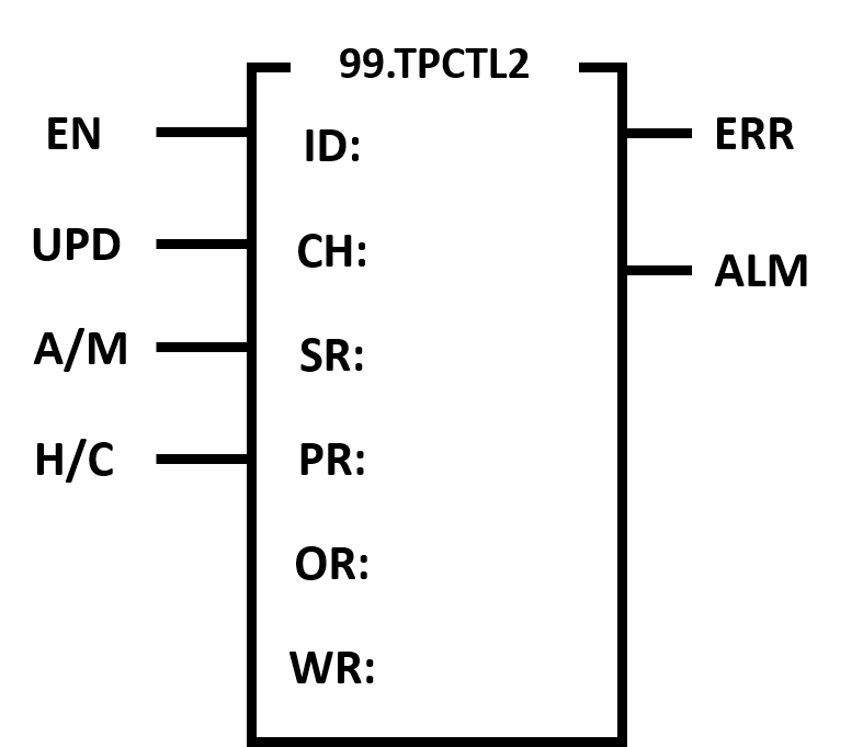
ID: The number of the expansion module used as the input signal CH: Channel number for input signal SR: Process control setup start register PR: Gain setup start register OR: Output start register WR: Working start register |
|||||||||||||||||||||||||||||||||||||||||||||||||||||||||||||||||
|
||||||||||||||||||||||||||||||||||||||||||||||||||||||||||||||||||
|
FUN99 P TPCTL2 |
PID temperature control instruction 2 |
FUN99 P TPCTL2 |
|
Description |
||
planning form to measure the current external temperature value as a Process Variable (PV), and the temperature Set Point (SP) set by the user, and the program-controlled variable through the software PID mathematical formula to obtain the appropriate output control value to control the temperature within the temperature range expected by the user.
|
||
|
FUN99 P TPCTL2 |
PID temperature control instruction 2 |
FUN99 P TPCTL2 |
|
PID control
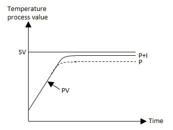
Even though abrupt change has resulted due to the noise influence, it can be restored to stabilized status through the derivative action. The smaller the derivative time, the lighter the fluctuation and the slower the noise reaction; on the contrary, it will become larger and quicker. Its scope is 0–3600s. If the derivative time becomes “0”, the system will not execute the derivative control. |
||
|
FUN99 P TPCTL2 |
PID temperature control instruction 2 |
FUN99 P TPCTL2 |
|||||||||||||||||||||
|
|||||||||||||||||||||||
|
FUN99 P TPCTL2 |
PID temperature control instruction 2 |
FUN99 P TPCTL2 |
|
||
|
FUN99 P TPCTL2 |
PID temperature control instruction 2 |
FUN99 P TPCTL2 |
|||||||||||||||||||||||||||||||||||||||
it for use.
|
|||||||||||||||||||||||||||||||||||||||||
|
FUN99 P TPCTL2 |
PID temperature control instruction 2 |
FUN99 P TPCTL2 |
|||||||||||||||||||||||||||||||||||||||
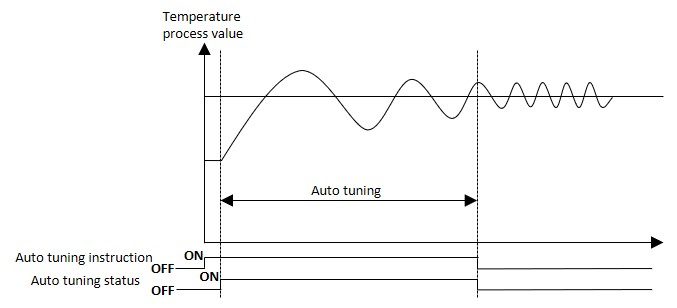
Auto tuning
|
|||||||||||||||||||||||||||||||||||||||||
|
FUN99 P TPCTL2 |
PID temperature control instruction 2 |
FUN99 P TPCTL2 |
|||||||||||||||||||||||||||||||||||||||
|
|||||||||||||||||||||||||||||||||||||||||
|
FUN99 P TPCTL2 |
PID temperature control instruction 2 |
FUN99 P TPCTL2 |
|
Auto Tuning Example |
SSR Example |
|
|
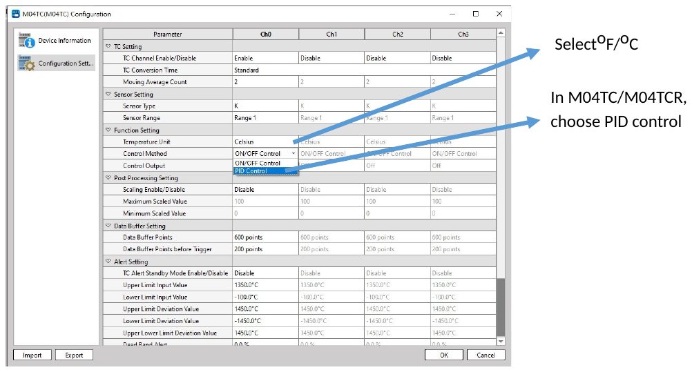
Step0 Related settings of M04TC/ M04TCR module
|
||
|
FUN99 P TPCTL2 |
PID temperature control instruction 2 |
FUN99 P TPCTL2 |
||||||||||||||||||||||||
|
Step1 Setting parameters: Fill in the required TS, SV, DOUT, PWM period, set the output upper limit to 1, the output lower limit to zero, and AT to 1, as shown in the figure below:
|
||||||||||||||||||||||||||
|
FUN99 P TPCTL2 |
PID temperature control instruction 2 |
FUN99 P TPCTL2 |
||||||||||||||||||||||||
|
||||||||||||||||||||||||||
|
FUN99 P TPCTL2 |
PID temperature control instruction 2 |
FUN99 P TPCTL2 |
||||||||||||||||||||||||
|
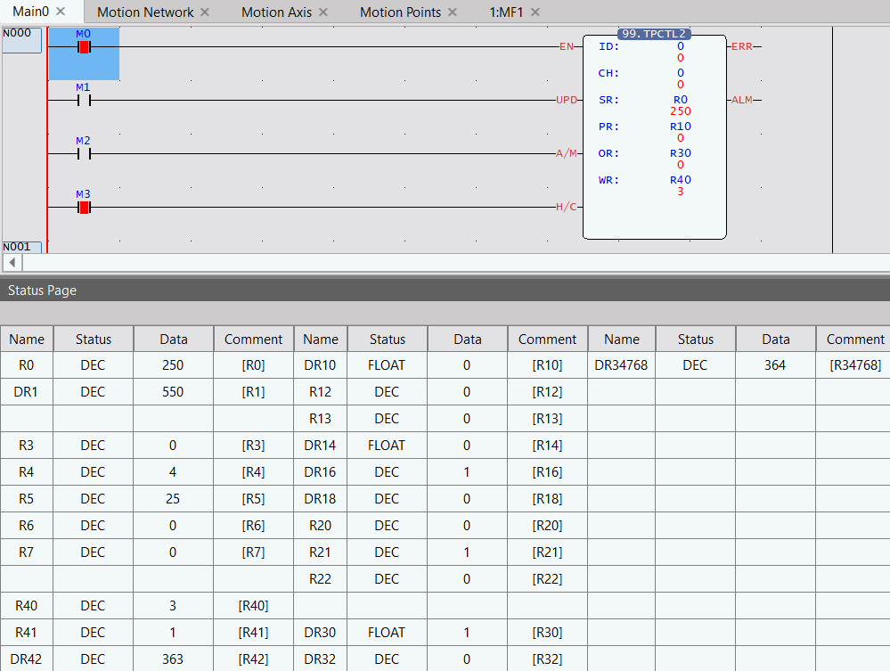
In Step2 Auto tuning: During Auto tuning, you need to wait for relevant parameters (Kp, Ki, Kd, Auto tuning status = 3, that is, Tune is completed), and Error will be output if it exceeds 2 hours. As shown below
|
||||||||||||||||||||||||||
|
FUN99 P TPCTL2 |
PID temperature control instruction 2 |
FUN99 P TPCTL2 |
||||||||||||||||||||||||
|
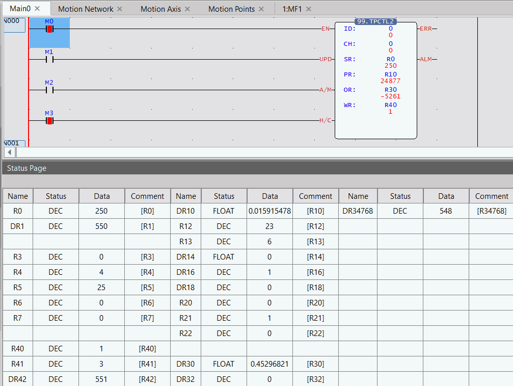
Step3 Auto tuning completed: After Auto tuning is completed, the relevant parameters Kp, Ki, and Kd should have corresponding parameters and Auto tuning status=3 As shown below
|
||||||||||||||||||||||||||
|
FUN99 P TPCTL2 |
PID temperature control instruction 2 |
FUN99 P TPCTL2 |
||||||||||||||||||||||||
|
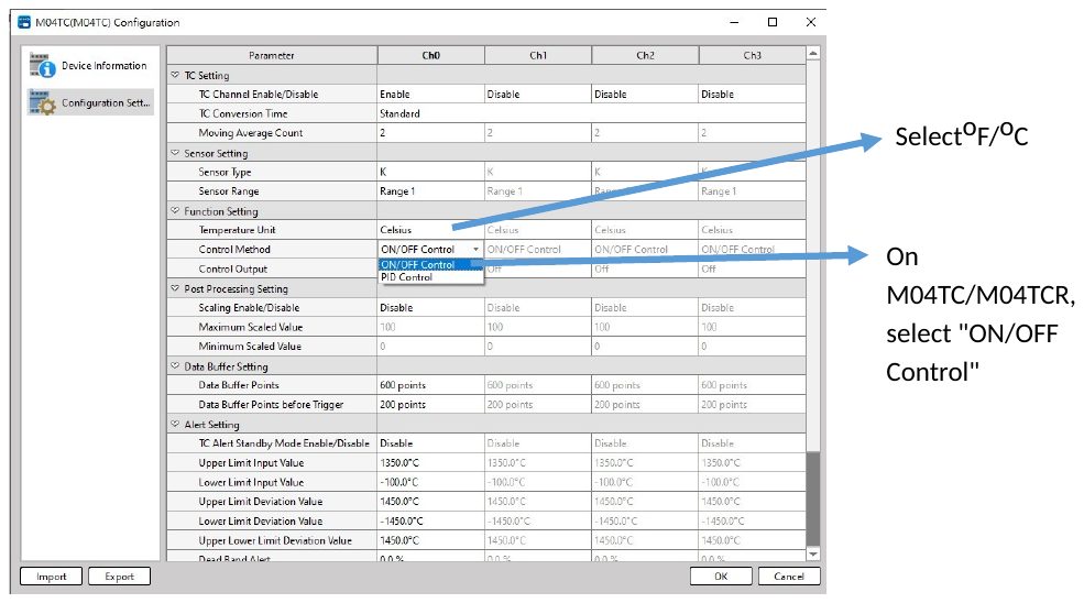
On/Off mode Example: |
||||||||||||||||||||||||||
|
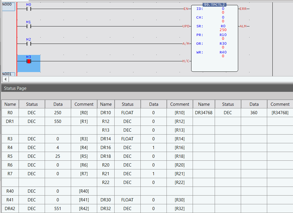
Step0 Related settings of M04TC/ M04TCR module
|
||||||||||||||||||||||||||
|
FUN99 P TPCTL2 |
PID temperature control instruction 2 |
FUN99 P TPCTL2 |
||||||||||||||||||||
|
On/Off mode Example: |
||||||||||||||||||||||
|
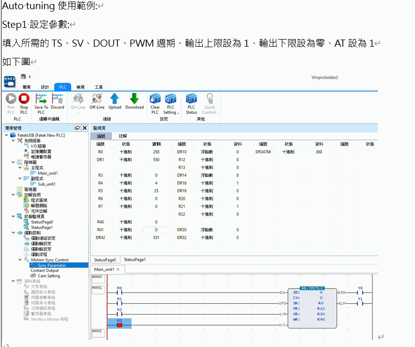
Step1 Fill in the required TS, SV, dead band, DOUT, output upper limit, output lower limit, and trigger the command
|
||||||||||||||||||||||
|
FUN99 P TPCTL2 |
PID temperature control instruction 2 |
FUN99 P TPCTL2 |
||||||||||||||||||||
|
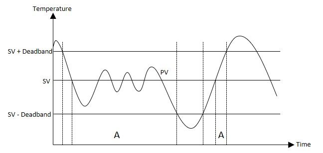
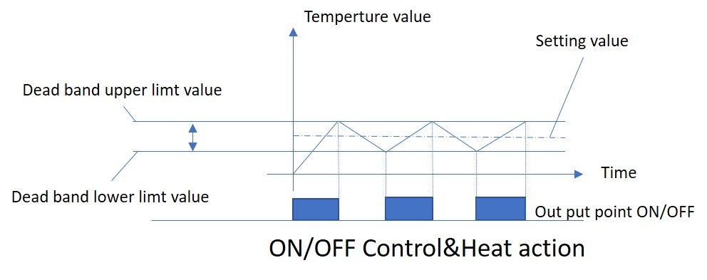
Schematic diagram of ON/OFF control action |
||||||||||||||||||||||
|
FUN99 P TPCTL2 |
PID temperature control instruction 2 |
FUN99 P TPCTL2 |
|
Auto tuning Example: |
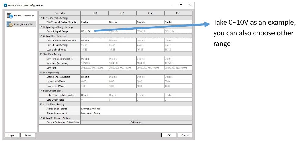
SCR example, this is an example with the M04DA analog output module |
|
|
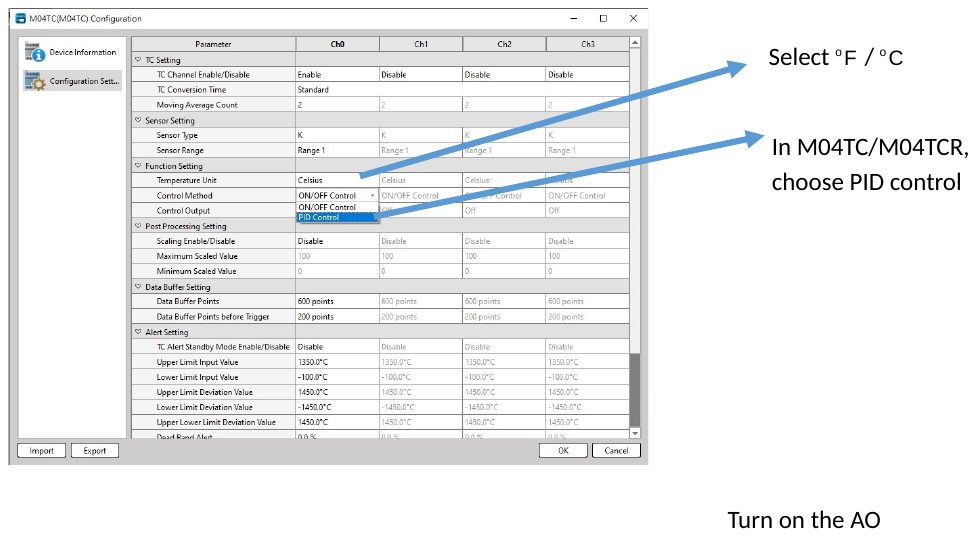
Step0 Related settings of M04TC/ M04TCR module
Related settings of M04DA/ M04DAR module
|
||
|
FUN99 P TPCTL2 |
PID temperature control instruction 2 |
FUN99 P TPCTL2 |
|
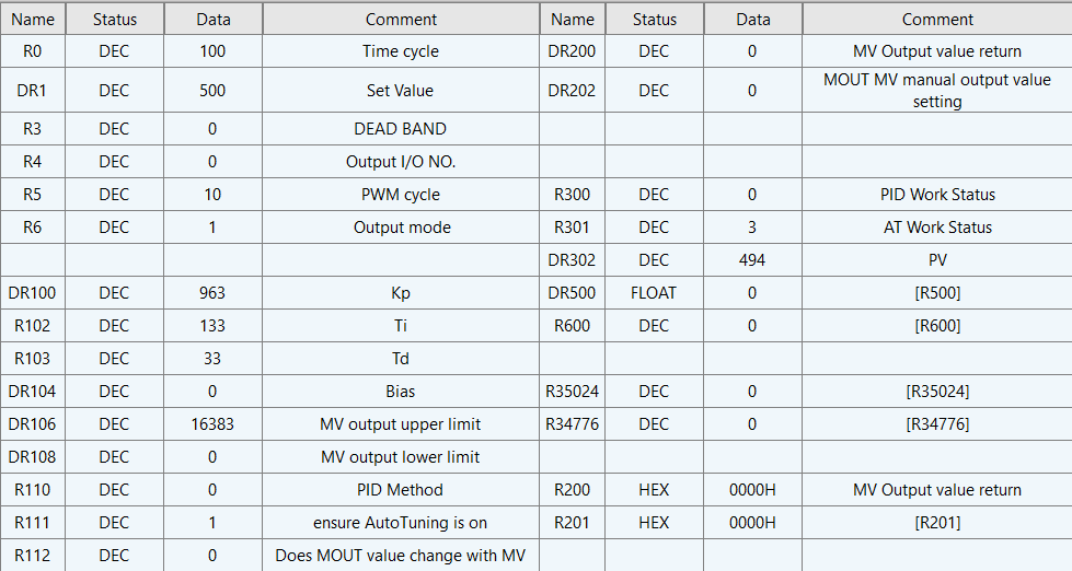
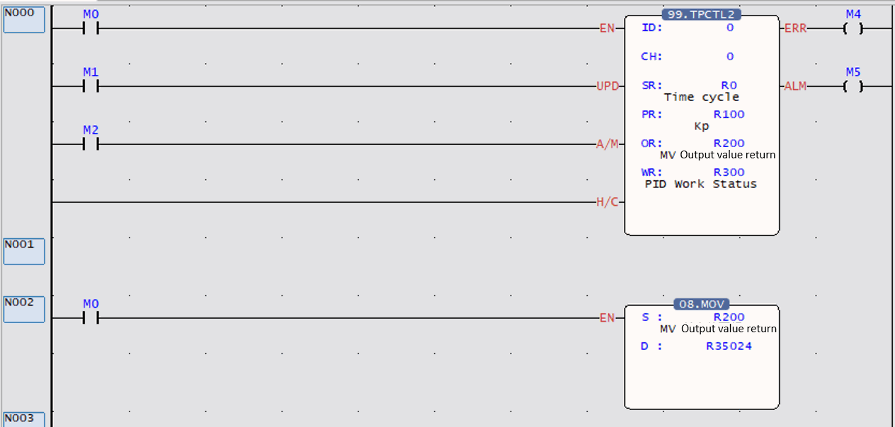
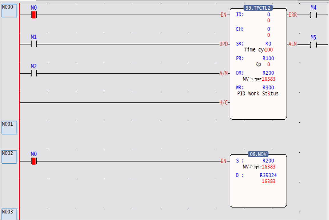
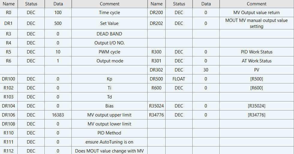
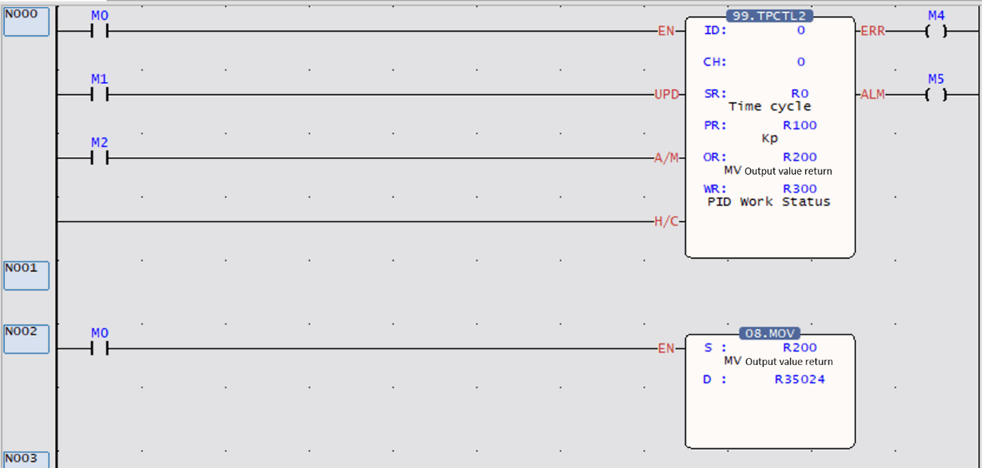
Step1 Setting parameters: Setting parameters and ladder diagram program, the detailed content and explanation of the table are on the next page
|
||
|
FUN99 P TPCTL2 |
PID temperature control instruction 2 |
FUN99 P TPCTL2 |
||||||||||||||||||||||||||||
The command H/C is short-circuited, which means that when there is output, it is heating control; if it is empty, it means cooling control After filling in the above setting values, you can turn M0 ON, trigger the command and perform Autotuning. |
||||||||||||||||||||||||||||||
|
FUN99 P TPCTL2 |
PID temperature control instruction 2 |
FUN99 P TPCTL2 |
||||||||||||||||
|
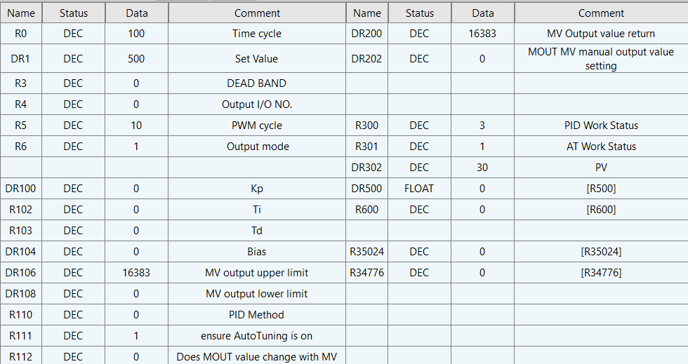
In Step2 Auto tuning: During Auto tuning, you only need to wait for relevant parameters (Kp, Ki, Kd appear, Auto tuning status = 3, that is, Tune is completed, you can enter Step 3), and Error will be output if it exceeds 2 hours. As shown below
|
||||||||||||||||||
|
FUN99 P TPCTL2 |
PID temperature control instruction 2 |
FUN99 P TPCTL2 |
||||||||||||||||
|
||||||||||||||||||
|
FUN99 P TPCTL2 |
PID temperature control instruction 2 |
FUN99 P TPCTL2 |
||||||||||||||||
|
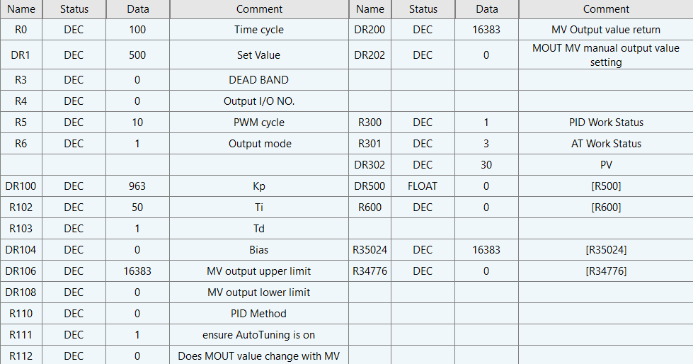
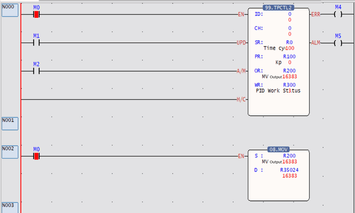
Step3 Auto tuning completed: After Auto tuning is completed, the relevant parameters Kp, Ki, and Kd should have corresponding parameters and Auto tuning status=3 As shown below:
|
||||||||||||||||||
|
FUN99 P TPCTL2 |
PID temperature control instruction 2 |
FUN99 P TPCTL2 |
||||||||||||||||
|
||||||||||||||||||
|
FUN99 P TPCTL2 |
PID temperature control instruction 2 |
FUN99 P TPCTL2 |
|
On/Off mode Example: |
||
|
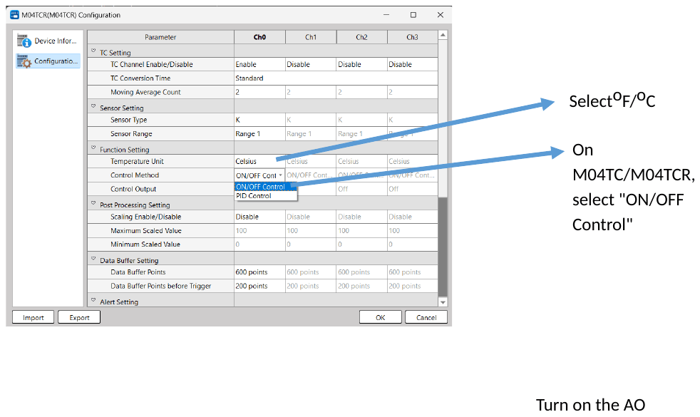
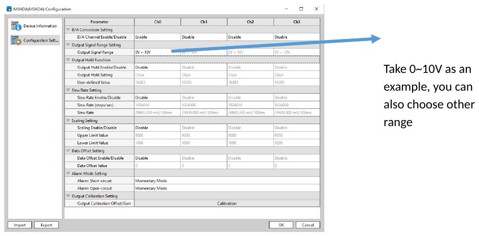
Step0 Related settings of M04TC/ M04TCR module
Related settings of M04DA/M04DAR module
|
||
|
FUN99 P TPCTL2 |
PID temperature control instruction 2 |
FUN99 P TPCTL2 |
||||||||||||||||||||||
|
On/Off mode Example: |
||||||||||||||||||||||||
|
Step1 Setting parameters: Setting parameters and ladder diagram program, the detailed content and explanation of the table are on the next page
|
||||||||||||||||||||||||
|
FUN99 P TPCTL2 |
PID temperature control instruction 2 |
FUN99 P TPCTL2 |
||||||||||||||||||||||
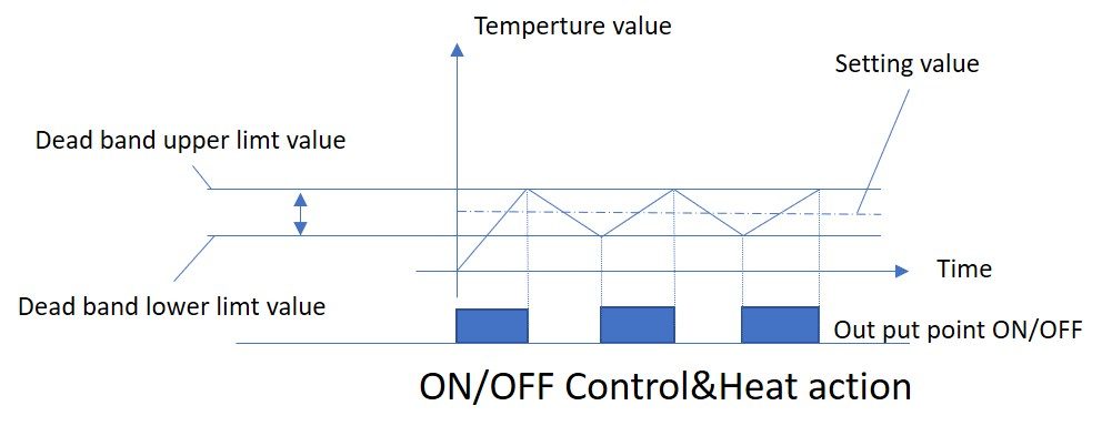
Schematic diagram of ON/OFF control action |
||||||||||||||||||||||||
13-2 General-Purpose PID Control Instruction Description and Examples
|
FUN38 PID2 |
PID 2 |
FUN38 PID2 |
||||||||||||||||||||||||||||||||||||||||||||||||||||||||
|
Symbol |
||||||||||||||||||||||||||||||||||||||||||||||||||||||||||
|
|
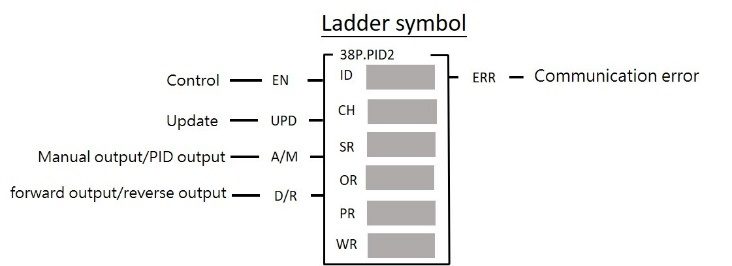
ID: The number of the expansion module used as the input signal. CH: Channel number for input signal. SR: The starting register number of the program-controlled setting value, occupying 8 registers in total. OR: PID output register number PR: The starting register number of the parameter setting value, occupying 7 registers in total WR: The initial number of the working register used by this command occupies 5 registers in total, and cannot be reused in other places. |
|||||||||||||||||||||||||||||||||||||||||||||||||||||||||
|
||||||||||||||||||||||||||||||||||||||||||||||||||||||||||
|
Function Description |
||||||||||||||||||||||||||||||||||||||||||||||||||||||||||
|
FUN38 PID2 |
PID 2 |
FUN38 PID2 |
Mn = [KpxEn]- [KpxTdx(PVn-PVn-1)/Ts] + Bias Mn = Control output at "n" time Kp: Proportional term real number (Range: ±(1.8*10-38~3.4*1038)) Ti: Integral time constant (range: 0~3600, equivalent to 0~3600 Repeats/Seconds) Td: Derivative time constant (range: 0~3600, equivalent to 0~3600 Seconds) PVn: Program-controlled variable value at "n" time PV n-1: The value of the program-controlled variable last time "n" En: Error at "n" time = set value (SP) – program variable value (PVn) at "n" time Ts: Interval time between PID operations (Range: 1~300, unit: 0.1s) Bias: Bias output (Range:±(1.8*10-38~3.4*1038)) |
||
|
FUN38 PID2 |
PID 2 |
FUN38 PID2 |
|
||
|
FUN38 PID2 |
PID 2 |
FUN38 PID2 |
|||||||||||||||||||||||||||||||||
|
|||||||||||||||||||||||||||||||||||
|
FUN38 PID2 |
PID 2 |
FUN38 PID2 |
|||||||||||||||||||||||||||||||||
it for use.
|
|||||||||||||||||||||||||||||||||||
|
FUN38 PID2 |
PID 2 |
FUN38 PID2 |
|||||||||||||||||||||||||||||||||
|
|||||||||||||||||||||||||||||||||||
|
FUN38 PID2 |
PID 2 |
FUN38 PID2 |
|
Auto tuning Example: |
SCR example, this is an example of M04DA analog output and M04AD analog input module |
|
|
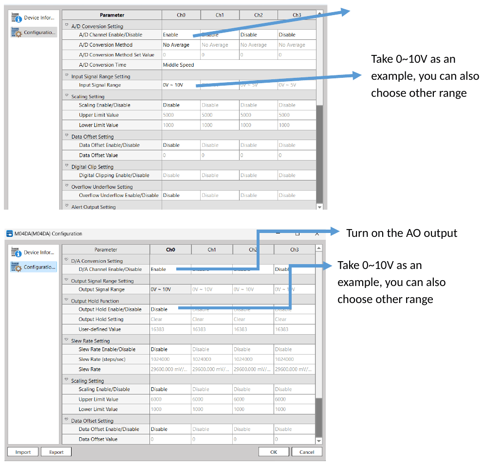
Step0 Open the conversion channel of the analog input Related settings of M04DA/ M04DAR module
Related settings of M04DA/ M04DAR module |
||
|
FUN38 PID2 |
PID 2 |
FUN38 PID2 |
|
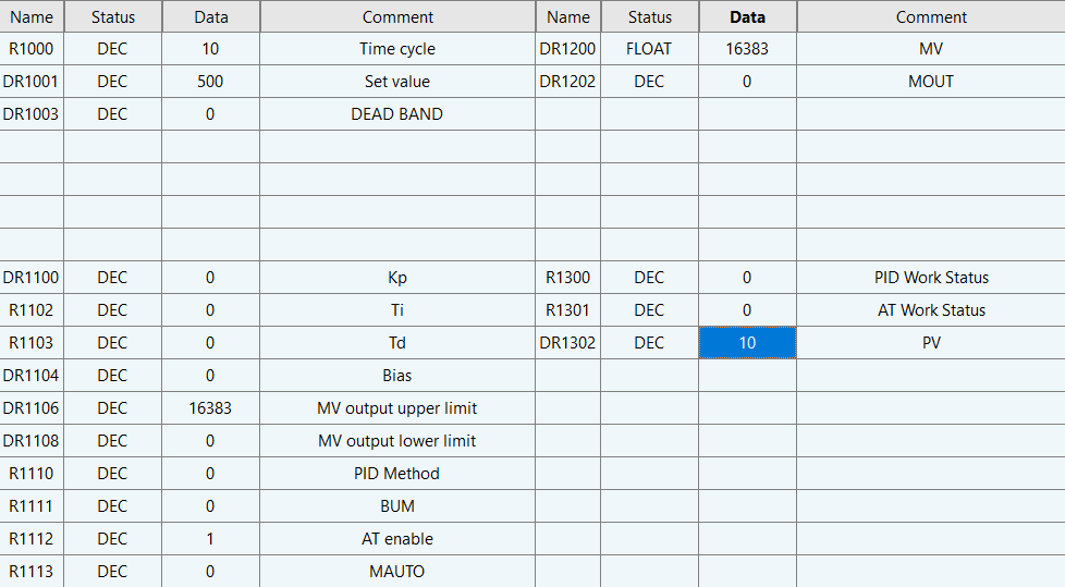
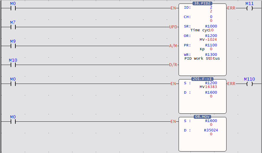
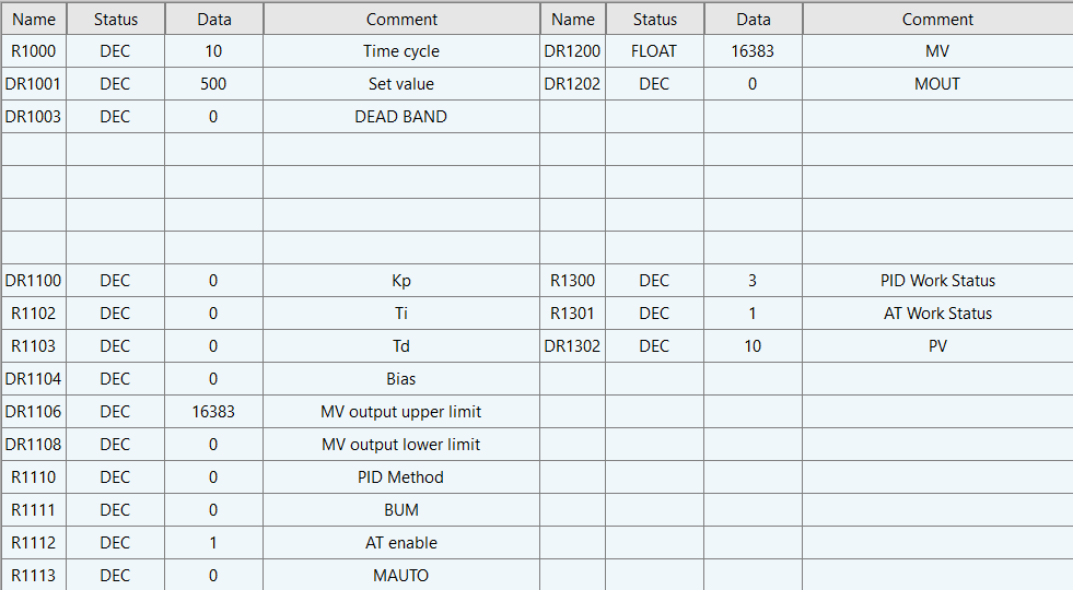
Step1 Setting parameters: Setting parameters and ladder diagram program, the detailed content and explanation of the table are on the next page.
|
||
|
FUN38 PID2 |
PID 2 |
FUN38 PID2 |
||||||||||||||||||
The command H/C is short-circuited, which means that when there is output, it is heating control; if it is empty, it means cooling control. After filling in the above setting values, you can turn M0 ON, trigger the command and perform Autotuning. |
||||||||||||||||||||
|
FUN38 PID2 |
PID 2 |
FUN38 PID2 |
||||||||||||||||
|
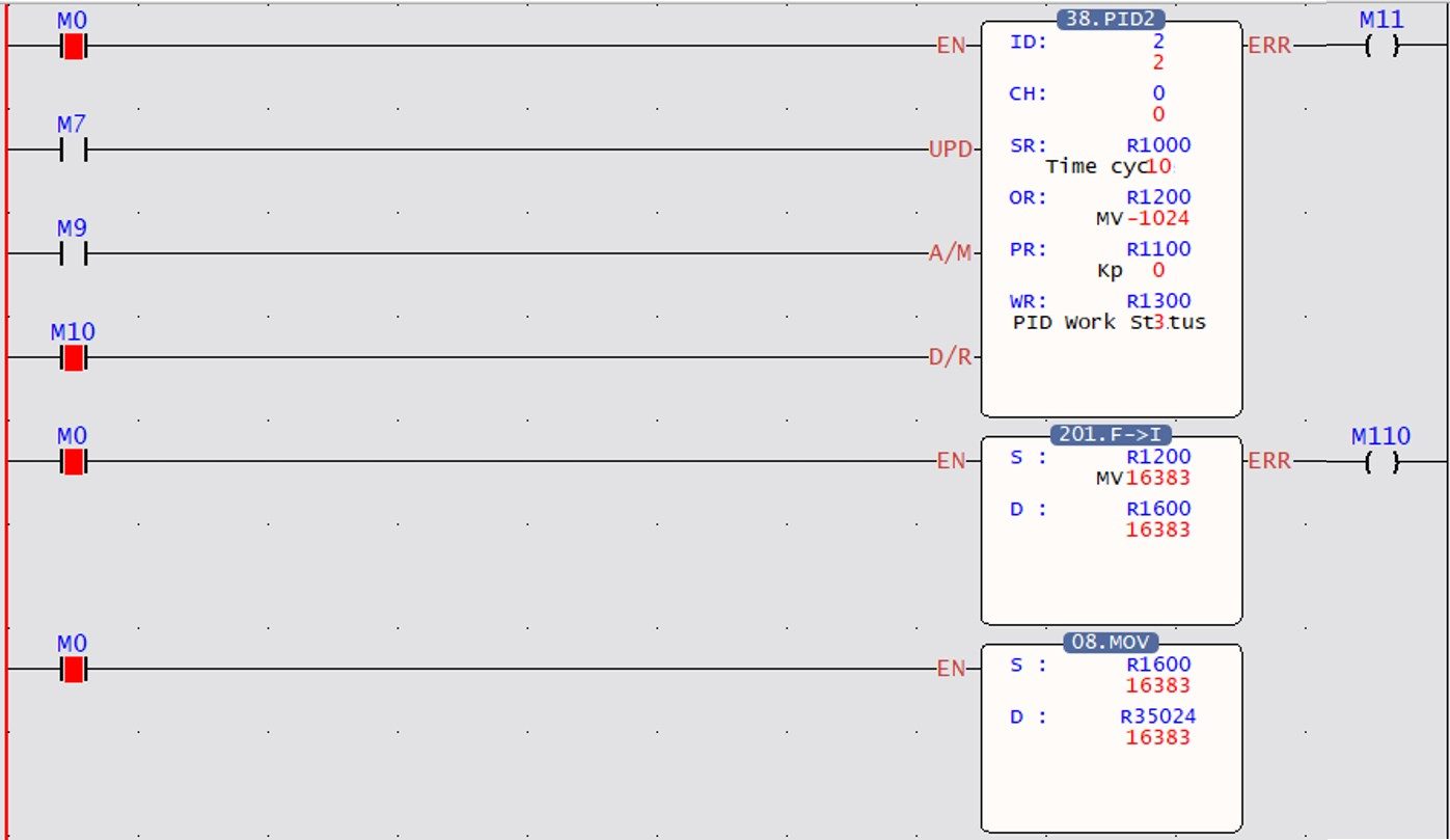
In Step2 Auto tuning: During Auto tuning, you only need to wait for relevant parameters (Kp, Ki, Kd appear, Auto tuning status = 3, that is, Tune is completed, you can enter Step 3), and Error will be output if it exceeds 2 hours. As shown below:
|
||||||||||||||||||
|
FUN38 PID2 |
PID 2 |
FUN38 PID2 |
||||||||||||||||
|
||||||||||||||||||
|
FUN38 PID2 |
PID 2 |
FUN38 PID2 |
||||||||||||||||
|
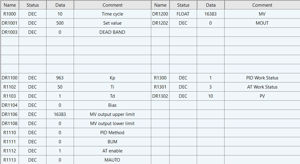
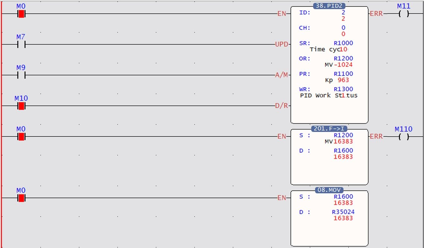
Step3 Auto tuning completed: After Auto tuning is completed, the relevant parameters Kp, Ki, and Kd should have corresponding parameters and Auto tuning status=3 As shown below:
|
||||||||||||||||||
|
FUN38 PID2 |
PID 2 |
FUN38 PID2 |
||||||||||||||||
|
||||||||||||||||||
13-3 General PID operation (Main Unit)
|
FUN30 PID |
General PID operation |
FUN30 PID |
|||||||||||||||||||||||||||||||||||
|
Symbol |
|||||||||||||||||||||||||||||||||||||
|
|
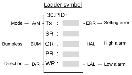
Ts:Solution interval between calculations SR:Starting register of loop settings ; OR:Output register of PID loop operation. PR:Starting register of loop parameters; WR:Staring register of working registers for this instruction ,it takes 5 registers and can’t be repeated in using. |
||||||||||||||||||||||||||||||||||||
|
|||||||||||||||||||||||||||||||||||||
|
Description |
|||||||||||||||||||||||||||||||||||||
|
FUN30 PID |
PID |
FUN30 PID |
Mn : Control output at "n" time Mn R35765 :The gain constant, the default is 1000, which can be set between 1~5000. Pb :Proportional band The expression stating the percent change in error required to change the output full scale. ( Range:1~5000,unit in 0.1%;Kc(gain)=R35765/P ) Ki : Integral tuning constant(range:0~9999,it means 0.00~99.99 Repeats/Minute) Td : Derivative tuning constant(range:0~3600,equivalent to 0~3600 Seconds) : Process variable at time "n" :Process variable when loop was last solved En : The difference between the set point (SP) and the process variable (PV) at time "n". En = SP – . Ts : Solution interval between calculations(Range:1~3000, unit in 0.01S) Bias : Offset to the output(Range:0~16383) |
||
|
FUN30 PID |
PID |
FUN30 PID |
|
|
|||
|
FUN30 PID |
PID |
FUN30 PID |
|
|
|||
|
FUN30 PID |
PID |
FUN30 PID |
|
||
|
FUN30 PID |
PID |
FUN30 PID |
(This is because the equation uses R35765 divided by Pb.) It must be the range:1 ≦ Pb ≦5000, unit is in 0.1%. Kc(gain)=R35765/ Pb; the default of R35765 is 1000, and it’s range is 1 ≦ R35765 ≦ 5000.
It must be the range:0 ≦ Ki ≦ 9999 (0.00~99.99 Repeats/Minute)
It must be the range:0 ≦ Td ≦ 9999 (0.00~99.99 Minutes) |
||
|
FUN30 PID |
PID |
FUN30 PID |
It must be the range:0 ≦ Bias ≦ 16383
It must be the range:1 ≦ HIWL ≦ 16383
It must be the range:0 ≦ LIWL ≦ 16383
=0 , Standard PID method; =1 , Minimum Overshoot Method; Method 0 is prefer because most applications using PI control (Td=0). The user may try method 1 when using PID control and the result is not stable.
|
||
|
FUN30 PID |
PID |
FUN30 PID |
Bit0 =0 , Manual operation mode =1 , Auto mode Bit1 : This bit will be a 1 during the scan the solution is being solved, and it is ON for a scan time. Bit2=1 , Bumpless transfer Bit4 : The status of "ERR" indication Bit5 : The status of "HAL" indication Bit6 : The status of "LAL" indication
|
||
|
FUN30 PID |
PID |
FUN30 PID |
|
|
|||
|
FUN30 PID |
PID |
FUN30 PID |
|
|
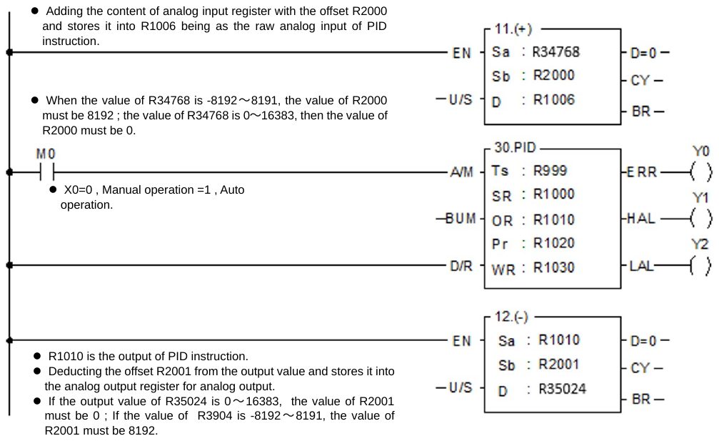
R999 :The setting of solution interval between calculations; for example the content of R999 is 200, it means it will perform this PID operation every 2 seconds. R1000 :Scaled process variable, which is the engineering unit loaded by the PID instruction every time it gets solved. A linear scaling is done on R1006 using the high and low engineering range found in R1004 and R1005. R1001 :Setpoint, it is the desired value the loop should control at; which is entered in engineering unit. For example the span of controlling process is 0°C~500°C, the setting of R1001 is equal to 100, it means the desired result is at 100°C. R1002 :The setting of high alarm limit; which is entered in engineering unit. R1003 :The setting of low alarm limit; which is entered in engineering unit. The example mentioned, if the setting of R1003 is equal to 95, it means there will have the low alarm while the loop is less than or equal to 95°C. R1004 :The setting of high engineering range. The example mentioned, if the setting of R1004 is equal to 500, it means the highest value of this loop is 500°C. R1005 :The setting of low engineering range. The example mentioned, if the setting of R1005 is equal to 0, it means the lowest value of this loop is 0°C. R1006 :Raw analog measurement; it is the value that the content of analog input register (R34768〜R34895) is added by the offset of 2048. R1007:Offset of process variable; let it be 0 if the raw analog signal and the span of the analog input module are all 0〜10V. |
R1020 :The setting of proportional band; for example the content of R1020 is 20, R1021 :The setting of integral tuning constant; R1022 :The setting of derivative tuning constant; for example the content of R1022 is 0, it means PI control. R1023 :The setting of the bias to the output; R1024 :The setting of high integral wind-up; R1025 :The setting of low integral wind-up; R1026 :The setting of PID method; R1030 = Loop status register Bit0 =0, Manual operation mode Bit1 : This bit will be a 1 during the scan the solution is being solved, and it is ON for Bit2=1 , Bumpless transfer Bit4 : The status of "ERR" indication Bit5 : The status of "HAL" indication Bit6 : The status of "LAL" indication R1031~R1034: They are the working registers, please refer to the description of operand WR. |
||
Tip: press ← → to switch chapters, Ctrl+K to search