Ladder Motion Commands
To execute Motion Control, the M-PLC Controller realizes the user motion sequence control by using motion flow with point table. When moving at the respective axis point, the JOG or the HOME. M-PLC also provides the ladder motion related block commands to the user.
The M-PLC Motion Control can be achieved through the following three methods: 1. Ladder control (refer to the ladder motion commands described in this chapter); 2. Motion Flow control (refer to Chapter 6: Introduction of Motion Flow); 3. Test Run (refer to Chapter 12: Introduction of Test Run). Described below is the application timing of the aforesaid three control methods:
|
Motion Control |
Content |
Application Timing |
Remark |
|
Ladder Control |
1. Position Control 2. JOG control 3. HOME Return 4. Handwheel 5. Speed Control 6. Torque Control 7. single axis positioning |
The Ladder is suitable for the convenient JOG control and the HOME return, etc. |
Please use the Motion Flow control method for controlling the complicated or continuous motion flow. |
|
Motion Flow Control |
1. Position Control 2. Speed Control 3. Torque control 4. HOME Return 5. Branch Control (the motion behavior required for controlling more than two processes concurrently). 6. Selective Control (conditional control) 7. Standby Setting 8. Merging 9. GoTo Conditional Jumping |
The Motion Flow is suitable for controlling complicated motion and continuous motion flow because it is very convenient and easier to use. |
The Motion Flow is also suitable for the multi-axis interpolated motion and Cam synchronization. |
|
Test Run |
1. Position Control 2. Speed Control 3. Torque Control 4. JOG Control |
During Test Run, convenient motion behavior adjustment will be executed or allow the first timer to test the quick motion. |
Such mode only applies to the test and inspection or adjustment, and it does not provide motion program control writing function. |
There are four types of motion control programming modes in this product:
- Basic motion control commands: They are used to start or stop the motion controller, and modify the data within the motion control project.
- Motion control mode 1: It is used to start the motion flow control program, and the content of the motion control table in the project is used as the motion parameters.
- Motion control mode 2: It is used to perform motion control on the ladder diagram, and the content of the motion control table in the project is still used as the motion parameters.
- Motion control mode 3: It is used for ladder program to perform motion control, with PLC registers data as motion parameters.
Through these four types of motion control commands, users can flexibly use them in three control modes according to their usage habits and device functions. It not only improves work efficiency, but also improves the readability of project procedures.
6-1 Motion Control Basic Commands
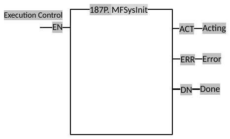
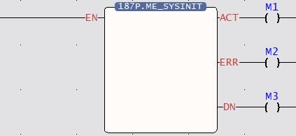
6-1-1 Fun187 System Initialization (MFSysInit)
|
Fun187 P MFSysInit |
System Initialization |
Fun187 P MFSysInit |
|||
|
Command Description |
|||||
|
Ladder Symbol
|
No Operand |
||||
|
unction Description |
|||||
|
|||||
|
Program Example |
|||||
|
Ladder
|
|||||
|
|||||
6-1-2 Fun177 Motion System Emergency Stop (MFSysStop)
|
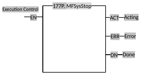
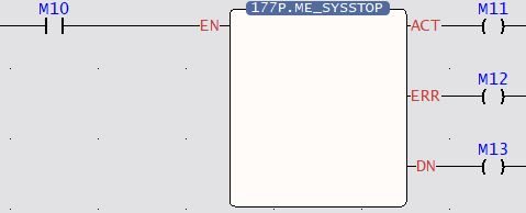
Fun177 P MFSysStop |
Motion System Emergency Stop |
Fun177 P MFSysStop |
|||
|
Command Description |
|||||
|
Ladder Symbol
|
No Opearand |
||||
|
Function Description |
|||||
|
|||||
|
Program Example |
|||||
|
Ladder
|
|||||
|
|||||
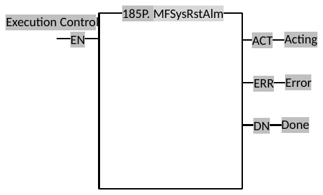
6-1-3 Fun185 Reset Motion Error Alarm (MFSysRstAlm)
|
Fun185 P MFSysRstAlm |
Reset Motion Error Alarm |
Fun185 P MFSysRstAlm |
|||
|
Command Description |
|||||
|
Ladder Symbol
|
Operand |
||||
|
Function Description |
|||||
|
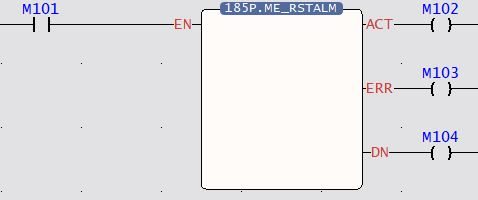
Clears all motion flow and driver error alarms. However, the communication alarm of the driver cannot be cleared by this command and needs to be powered on again.
|
|||||
|
Program Example |
|||||
|
Ladder
|
|||||
|
|||||
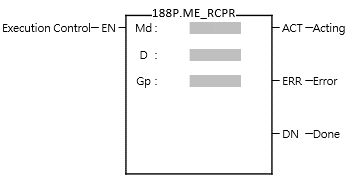
6-1-4 Fun188 Read Motion Control Recipe
|
Fun188 MFSysRCPR |
Read Motion Control Recipe |
Fun188 MFSysRCPR |
|||||||||||||||||||||||||||||||||||||||||||||||||||||||||||||||||||||||||||||||||||||||||||||||||||||||||||||||||||||||||||||||||||||||||||||||||||||||||||||||||||||||||||||||||||||||||||||||||||||||||||||||||||||||||||||||||||||||||||||||||||||||||||||||||||||||||||||||||||||||||||||||||||||||||||||||||||||||||||||||||||||||||||||||||||||||||||||||||||||||||||||||||||||||||||||||||||||||||||||||||||||||||||||||||||||||||||||||||||||||||||||||||||||||||||||||||||||||||||||||||||||||||||||||||||||||||||||||||||||||||||||||||||||||||||||||||||||||||||||||||||||||||||||||||||||||||||||||||||||||||||||||||||||||||||||||||||||||||||||||||||||||||||||||||||||||||||||||||||||||||||||||||||||||||||||||||||||||||||||||||||||||||||||||||||||||||||||||||||||||||||||||||||||||||||||||||||||||||||||||||||||||||||||||||||||||||||||||||||||||||||||||||||||||||||||||||||||||||||||||||||||||||||||||||||||||||||||||||||||||||||||||||||||||||||||||||||||||||||||||||||||||||||||||||||||||||||||||||||||
|
Command Description |
|||||||||||||||||||||||||||||||||||||||||||||||||||||||||||||||||||||||||||||||||||||||||||||||||||||||||||||||||||||||||||||||||||||||||||||||||||||||||||||||||||||||||||||||||||||||||||||||||||||||||||||||||||||||||||||||||||||||||||||||||||||||||||||||||||||||||||||||||||||||||||||||||||||||||||||||||||||||||||||||||||||||||||||||||||||||||||||||||||||||||||||||||||||||||||||||||||||||||||||||||||||||||||||||||||||||||||||||||||||||||||||||||||||||||||||||||||||||||||||||||||||||||||||||||||||||||||||||||||||||||||||||||||||||||||||||||||||||||||||||||||||||||||||||||||||||||||||||||||||||||||||||||||||||||||||||||||||||||||||||||||||||||||||||||||||||||||||||||||||||||||||||||||||||||||||||||||||||||||||||||||||||||||||||||||||||||||||||||||||||||||||||||||||||||||||||||||||||||||||||||||||||||||||||||||||||||||||||||||||||||||||||||||||||||||||||||||||||||||||||||||||||||||||||||||||||||||||||||||||||||||||||||||||||||||||||||||||||||||||||||||||||||||||||||||||||||||||||||||||||
|
Ladder Symbol
|
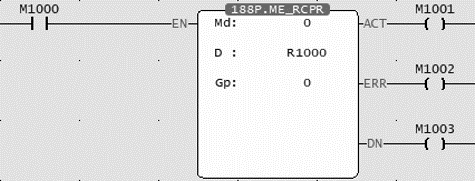
Operand Md: Mode D: Initial register of Recipe Gp: Read the column of the recipe table |
||||||||||||||||||||||||||||||||||||||||||||||||||||||||||||||||||||||||||||||||||||||||||||||||||||||||||||||||||||||||||||||||||||||||||||||||||||||||||||||||||||||||||||||||||||||||||||||||||||||||||||||||||||||||||||||||||||||||||||||||||||||||||||||||||||||||||||||||||||||||||||||||||||||||||||||||||||||||||||||||||||||||||||||||||||||||||||||||||||||||||||||||||||||||||||||||||||||||||||||||||||||||||||||||||||||||||||||||||||||||||||||||||||||||||||||||||||||||||||||||||||||||||||||||||||||||||||||||||||||||||||||||||||||||||||||||||||||||||||||||||||||||||||||||||||||||||||||||||||||||||||||||||||||||||||||||||||||||||||||||||||||||||||||||||||||||||||||||||||||||||||||||||||||||||||||||||||||||||||||||||||||||||||||||||||||||||||||||||||||||||||||||||||||||||||||||||||||||||||||||||||||||||||||||||||||||||||||||||||||||||||||||||||||||||||||||||||||||||||||||||||||||||||||||||||||||||||||||||||||||||||||||||||||||||||||||||||||||||||||||||||||||||||||||||||||||||||||||||||||
|
Relay and Register
|
|||||||||||||||||||||||||||||||||||||||||||||||||||||||||||||||||||||||||||||||||||||||||||||||||||||||||||||||||||||||||||||||||||||||||||||||||||||||||||||||||||||||||||||||||||||||||||||||||||||||||||||||||||||||||||||||||||||||||||||||||||||||||||||||||||||||||||||||||||||||||||||||||||||||||||||||||||||||||||||||||||||||||||||||||||||||||||||||||||||||||||||||||||||||||||||||||||||||||||||||||||||||||||||||||||||||||||||||||||||||||||||||||||||||||||||||||||||||||||||||||||||||||||||||||||||||||||||||||||||||||||||||||||||||||||||||||||||||||||||||||||||||||||||||||||||||||||||||||||||||||||||||||||||||||||||||||||||||||||||||||||||||||||||||||||||||||||||||||||||||||||||||||||||||||||||||||||||||||||||||||||||||||||||||||||||||||||||||||||||||||||||||||||||||||||||||||||||||||||||||||||||||||||||||||||||||||||||||||||||||||||||||||||||||||||||||||||||||||||||||||||||||||||||||||||||||||||||||||||||||||||||||||||||||||||||||||||||||||||||||||||||||||||||||||||||||||||||||||||||||
|
Function Description |
|||||||||||||||||||||||||||||||||||||||||||||||||||||||||||||||||||||||||||||||||||||||||||||||||||||||||||||||||||||||||||||||||||||||||||||||||||||||||||||||||||||||||||||||||||||||||||||||||||||||||||||||||||||||||||||||||||||||||||||||||||||||||||||||||||||||||||||||||||||||||||||||||||||||||||||||||||||||||||||||||||||||||||||||||||||||||||||||||||||||||||||||||||||||||||||||||||||||||||||||||||||||||||||||||||||||||||||||||||||||||||||||||||||||||||||||||||||||||||||||||||||||||||||||||||||||||||||||||||||||||||||||||||||||||||||||||||||||||||||||||||||||||||||||||||||||||||||||||||||||||||||||||||||||||||||||||||||||||||||||||||||||||||||||||||||||||||||||||||||||||||||||||||||||||||||||||||||||||||||||||||||||||||||||||||||||||||||||||||||||||||||||||||||||||||||||||||||||||||||||||||||||||||||||||||||||||||||||||||||||||||||||||||||||||||||||||||||||||||||||||||||||||||||||||||||||||||||||||||||||||||||||||||||||||||||||||||||||||||||||||||||||||||||||||||||||||||||||||||||||
Md (Mode): 0 uses PLC Register , 1 gets data from the SD card D (Recipe Initial Register): Md = 0 meaningless , Md = 1 SD card recipe file number Gp (Read the column of the recipe table): Read the column of the recipe table, 0 read all
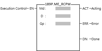
When the execution control [EN] changes from 1→0, all output indications are reset.
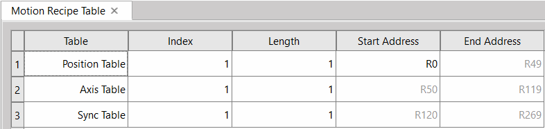
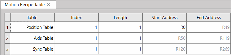
Recipe Table 【Project Management】>【Motion Control】>【Motion Recipe】
Tables: Point table, Axis table, Synchronization table
Length : consecutive point table or consecuitive axis Initial Address: The initial address of the register for reading and writing recipes
Recipe Point Table
Recipe Axis Table
Recipe Synchronous Table
|
|||||||||||||||||||||||||||||||||||||||||||||||||||||||||||||||||||||||||||||||||||||||||||||||||||||||||||||||||||||||||||||||||||||||||||||||||||||||||||||||||||||||||||||||||||||||||||||||||||||||||||||||||||||||||||||||||||||||||||||||||||||||||||||||||||||||||||||||||||||||||||||||||||||||||||||||||||||||||||||||||||||||||||||||||||||||||||||||||||||||||||||||||||||||||||||||||||||||||||||||||||||||||||||||||||||||||||||||||||||||||||||||||||||||||||||||||||||||||||||||||||||||||||||||||||||||||||||||||||||||||||||||||||||||||||||||||||||||||||||||||||||||||||||||||||||||||||||||||||||||||||||||||||||||||||||||||||||||||||||||||||||||||||||||||||||||||||||||||||||||||||||||||||||||||||||||||||||||||||||||||||||||||||||||||||||||||||||||||||||||||||||||||||||||||||||||||||||||||||||||||||||||||||||||||||||||||||||||||||||||||||||||||||||||||||||||||||||||||||||||||||||||||||||||||||||||||||||||||||||||||||||||||||||||||||||||||||||||||||||||||||||||||||||||||||||||||||||||||||||||
|
Program Example |
|||||||||||||||||||||||||||||||||||||||||||||||||||||||||||||||||||||||||||||||||||||||||||||||||||||||||||||||||||||||||||||||||||||||||||||||||||||||||||||||||||||||||||||||||||||||||||||||||||||||||||||||||||||||||||||||||||||||||||||||||||||||||||||||||||||||||||||||||||||||||||||||||||||||||||||||||||||||||||||||||||||||||||||||||||||||||||||||||||||||||||||||||||||||||||||||||||||||||||||||||||||||||||||||||||||||||||||||||||||||||||||||||||||||||||||||||||||||||||||||||||||||||||||||||||||||||||||||||||||||||||||||||||||||||||||||||||||||||||||||||||||||||||||||||||||||||||||||||||||||||||||||||||||||||||||||||||||||||||||||||||||||||||||||||||||||||||||||||||||||||||||||||||||||||||||||||||||||||||||||||||||||||||||||||||||||||||||||||||||||||||||||||||||||||||||||||||||||||||||||||||||||||||||||||||||||||||||||||||||||||||||||||||||||||||||||||||||||||||||||||||||||||||||||||||||||||||||||||||||||||||||||||||||||||||||||||||||||||||||||||||||||||||||||||||||||||||||||||||||||
|
Ladder
|
|||||||||||||||||||||||||||||||||||||||||||||||||||||||||||||||||||||||||||||||||||||||||||||||||||||||||||||||||||||||||||||||||||||||||||||||||||||||||||||||||||||||||||||||||||||||||||||||||||||||||||||||||||||||||||||||||||||||||||||||||||||||||||||||||||||||||||||||||||||||||||||||||||||||||||||||||||||||||||||||||||||||||||||||||||||||||||||||||||||||||||||||||||||||||||||||||||||||||||||||||||||||||||||||||||||||||||||||||||||||||||||||||||||||||||||||||||||||||||||||||||||||||||||||||||||||||||||||||||||||||||||||||||||||||||||||||||||||||||||||||||||||||||||||||||||||||||||||||||||||||||||||||||||||||||||||||||||||||||||||||||||||||||||||||||||||||||||||||||||||||||||||||||||||||||||||||||||||||||||||||||||||||||||||||||||||||||||||||||||||||||||||||||||||||||||||||||||||||||||||||||||||||||||||||||||||||||||||||||||||||||||||||||||||||||||||||||||||||||||||||||||||||||||||||||||||||||||||||||||||||||||||||||||||||||||||||||||||||||||||||||||||||||||||||||||||||||||||||||||||
|
|||||||||||||||||||||||||||||||||||||||||||||||||||||||||||||||||||||||||||||||||||||||||||||||||||||||||||||||||||||||||||||||||||||||||||||||||||||||||||||||||||||||||||||||||||||||||||||||||||||||||||||||||||||||||||||||||||||||||||||||||||||||||||||||||||||||||||||||||||||||||||||||||||||||||||||||||||||||||||||||||||||||||||||||||||||||||||||||||||||||||||||||||||||||||||||||||||||||||||||||||||||||||||||||||||||||||||||||||||||||||||||||||||||||||||||||||||||||||||||||||||||||||||||||||||||||||||||||||||||||||||||||||||||||||||||||||||||||||||||||||||||||||||||||||||||||||||||||||||||||||||||||||||||||||||||||||||||||||||||||||||||||||||||||||||||||||||||||||||||||||||||||||||||||||||||||||||||||||||||||||||||||||||||||||||||||||||||||||||||||||||||||||||||||||||||||||||||||||||||||||||||||||||||||||||||||||||||||||||||||||||||||||||||||||||||||||||||||||||||||||||||||||||||||||||||||||||||||||||||||||||||||||||||||||||||||||||||||||||||||||||||||||||||||||||||||||||||||||||||||
6-1-5 Fun189 Write Motion Control Recipe
|
Fun189 MFSysRCPW |
Write Motion Control Recipe |
Fun189 MFSysRCPW |
|||||||||||||||||||||||||||||||||||||||||||||||||||||||||||||||||||||||||||||||||||||||||||||||||||||||||||||||||||||||||||||||||||||||||||||||||||||||||||||||||||||||||||||||||||||||||||||||||||||||||||||||||||||||||||||||||||||||||||||||||||||||||||||||||||||||||||||||||||||||||||||||||||||||||||||||||||||||||||||||||||||||||||||||||||||||||||||||||||||||||||||||||||||||||||||||||||||||||||||||||||||||||||||||||||||||||||||||||||||||||||||||||||||||||||||||||||||||||||||||||||||||||||||||||||||||||||||||||||||||||||||||||||||||||||||||||||||||||||||||||||||||||||||||||||||||||||||||||||||||||||||||||||||||||||||||||||||||||||||||||||||||||||||||||||||||||||||||||||||||||||||||||||||||||||||||||||||||||||||||||||||||||||||||||||||||||||||||||||||||||||||||||||||||||||||||||||||||||||||||||||||||||||||||||||||||||||||||||||||||||||||||||||||||||||||||||||||||||||||||||||||||||||||||||||||||||||||||||||||||||||||||||||||||||||||||||||||||||||||||||||||||||||||||||||||||||||||||||||||
|
Command Description |
|||||||||||||||||||||||||||||||||||||||||||||||||||||||||||||||||||||||||||||||||||||||||||||||||||||||||||||||||||||||||||||||||||||||||||||||||||||||||||||||||||||||||||||||||||||||||||||||||||||||||||||||||||||||||||||||||||||||||||||||||||||||||||||||||||||||||||||||||||||||||||||||||||||||||||||||||||||||||||||||||||||||||||||||||||||||||||||||||||||||||||||||||||||||||||||||||||||||||||||||||||||||||||||||||||||||||||||||||||||||||||||||||||||||||||||||||||||||||||||||||||||||||||||||||||||||||||||||||||||||||||||||||||||||||||||||||||||||||||||||||||||||||||||||||||||||||||||||||||||||||||||||||||||||||||||||||||||||||||||||||||||||||||||||||||||||||||||||||||||||||||||||||||||||||||||||||||||||||||||||||||||||||||||||||||||||||||||||||||||||||||||||||||||||||||||||||||||||||||||||||||||||||||||||||||||||||||||||||||||||||||||||||||||||||||||||||||||||||||||||||||||||||||||||||||||||||||||||||||||||||||||||||||||||||||||||||||||||||||||||||||||||||||||||||||||||||||||||||||||||
|
Ladder Symbol
|
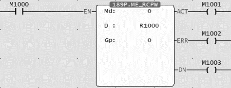
Operands Md: Mode D: Initial Recipe Register Gp: Write to the column of the recipe table |
||||||||||||||||||||||||||||||||||||||||||||||||||||||||||||||||||||||||||||||||||||||||||||||||||||||||||||||||||||||||||||||||||||||||||||||||||||||||||||||||||||||||||||||||||||||||||||||||||||||||||||||||||||||||||||||||||||||||||||||||||||||||||||||||||||||||||||||||||||||||||||||||||||||||||||||||||||||||||||||||||||||||||||||||||||||||||||||||||||||||||||||||||||||||||||||||||||||||||||||||||||||||||||||||||||||||||||||||||||||||||||||||||||||||||||||||||||||||||||||||||||||||||||||||||||||||||||||||||||||||||||||||||||||||||||||||||||||||||||||||||||||||||||||||||||||||||||||||||||||||||||||||||||||||||||||||||||||||||||||||||||||||||||||||||||||||||||||||||||||||||||||||||||||||||||||||||||||||||||||||||||||||||||||||||||||||||||||||||||||||||||||||||||||||||||||||||||||||||||||||||||||||||||||||||||||||||||||||||||||||||||||||||||||||||||||||||||||||||||||||||||||||||||||||||||||||||||||||||||||||||||||||||||||||||||||||||||||||||||||||||||||||||||||||||||||||||||||||||||||
|
Relay and Register
|
|||||||||||||||||||||||||||||||||||||||||||||||||||||||||||||||||||||||||||||||||||||||||||||||||||||||||||||||||||||||||||||||||||||||||||||||||||||||||||||||||||||||||||||||||||||||||||||||||||||||||||||||||||||||||||||||||||||||||||||||||||||||||||||||||||||||||||||||||||||||||||||||||||||||||||||||||||||||||||||||||||||||||||||||||||||||||||||||||||||||||||||||||||||||||||||||||||||||||||||||||||||||||||||||||||||||||||||||||||||||||||||||||||||||||||||||||||||||||||||||||||||||||||||||||||||||||||||||||||||||||||||||||||||||||||||||||||||||||||||||||||||||||||||||||||||||||||||||||||||||||||||||||||||||||||||||||||||||||||||||||||||||||||||||||||||||||||||||||||||||||||||||||||||||||||||||||||||||||||||||||||||||||||||||||||||||||||||||||||||||||||||||||||||||||||||||||||||||||||||||||||||||||||||||||||||||||||||||||||||||||||||||||||||||||||||||||||||||||||||||||||||||||||||||||||||||||||||||||||||||||||||||||||||||||||||||||||||||||||||||||||||||||||||||||||||||||||||||||||||||
|
Function Description |
|||||||||||||||||||||||||||||||||||||||||||||||||||||||||||||||||||||||||||||||||||||||||||||||||||||||||||||||||||||||||||||||||||||||||||||||||||||||||||||||||||||||||||||||||||||||||||||||||||||||||||||||||||||||||||||||||||||||||||||||||||||||||||||||||||||||||||||||||||||||||||||||||||||||||||||||||||||||||||||||||||||||||||||||||||||||||||||||||||||||||||||||||||||||||||||||||||||||||||||||||||||||||||||||||||||||||||||||||||||||||||||||||||||||||||||||||||||||||||||||||||||||||||||||||||||||||||||||||||||||||||||||||||||||||||||||||||||||||||||||||||||||||||||||||||||||||||||||||||||||||||||||||||||||||||||||||||||||||||||||||||||||||||||||||||||||||||||||||||||||||||||||||||||||||||||||||||||||||||||||||||||||||||||||||||||||||||||||||||||||||||||||||||||||||||||||||||||||||||||||||||||||||||||||||||||||||||||||||||||||||||||||||||||||||||||||||||||||||||||||||||||||||||||||||||||||||||||||||||||||||||||||||||||||||||||||||||||||||||||||||||||||||||||||||||||||||||||||||||||||
|
|||||||||||||||||||||||||||||||||||||||||||||||||||||||||||||||||||||||||||||||||||||||||||||||||||||||||||||||||||||||||||||||||||||||||||||||||||||||||||||||||||||||||||||||||||||||||||||||||||||||||||||||||||||||||||||||||||||||||||||||||||||||||||||||||||||||||||||||||||||||||||||||||||||||||||||||||||||||||||||||||||||||||||||||||||||||||||||||||||||||||||||||||||||||||||||||||||||||||||||||||||||||||||||||||||||||||||||||||||||||||||||||||||||||||||||||||||||||||||||||||||||||||||||||||||||||||||||||||||||||||||||||||||||||||||||||||||||||||||||||||||||||||||||||||||||||||||||||||||||||||||||||||||||||||||||||||||||||||||||||||||||||||||||||||||||||||||||||||||||||||||||||||||||||||||||||||||||||||||||||||||||||||||||||||||||||||||||||||||||||||||||||||||||||||||||||||||||||||||||||||||||||||||||||||||||||||||||||||||||||||||||||||||||||||||||||||||||||||||||||||||||||||||||||||||||||||||||||||||||||||||||||||||||||||||||||||||||||||||||||||||||||||||||||||||||||||||||||||||||||
|
Program Example |
|||||||||||||||||||||||||||||||||||||||||||||||||||||||||||||||||||||||||||||||||||||||||||||||||||||||||||||||||||||||||||||||||||||||||||||||||||||||||||||||||||||||||||||||||||||||||||||||||||||||||||||||||||||||||||||||||||||||||||||||||||||||||||||||||||||||||||||||||||||||||||||||||||||||||||||||||||||||||||||||||||||||||||||||||||||||||||||||||||||||||||||||||||||||||||||||||||||||||||||||||||||||||||||||||||||||||||||||||||||||||||||||||||||||||||||||||||||||||||||||||||||||||||||||||||||||||||||||||||||||||||||||||||||||||||||||||||||||||||||||||||||||||||||||||||||||||||||||||||||||||||||||||||||||||||||||||||||||||||||||||||||||||||||||||||||||||||||||||||||||||||||||||||||||||||||||||||||||||||||||||||||||||||||||||||||||||||||||||||||||||||||||||||||||||||||||||||||||||||||||||||||||||||||||||||||||||||||||||||||||||||||||||||||||||||||||||||||||||||||||||||||||||||||||||||||||||||||||||||||||||||||||||||||||||||||||||||||||||||||||||||||||||||||||||||||||||||||||||||||||
|
Ladder
|
|||||||||||||||||||||||||||||||||||||||||||||||||||||||||||||||||||||||||||||||||||||||||||||||||||||||||||||||||||||||||||||||||||||||||||||||||||||||||||||||||||||||||||||||||||||||||||||||||||||||||||||||||||||||||||||||||||||||||||||||||||||||||||||||||||||||||||||||||||||||||||||||||||||||||||||||||||||||||||||||||||||||||||||||||||||||||||||||||||||||||||||||||||||||||||||||||||||||||||||||||||||||||||||||||||||||||||||||||||||||||||||||||||||||||||||||||||||||||||||||||||||||||||||||||||||||||||||||||||||||||||||||||||||||||||||||||||||||||||||||||||||||||||||||||||||||||||||||||||||||||||||||||||||||||||||||||||||||||||||||||||||||||||||||||||||||||||||||||||||||||||||||||||||||||||||||||||||||||||||||||||||||||||||||||||||||||||||||||||||||||||||||||||||||||||||||||||||||||||||||||||||||||||||||||||||||||||||||||||||||||||||||||||||||||||||||||||||||||||||||||||||||||||||||||||||||||||||||||||||||||||||||||||||||||||||||||||||||||||||||||||||||||||||||||||||||||||||||||||||||
|
|||||||||||||||||||||||||||||||||||||||||||||||||||||||||||||||||||||||||||||||||||||||||||||||||||||||||||||||||||||||||||||||||||||||||||||||||||||||||||||||||||||||||||||||||||||||||||||||||||||||||||||||||||||||||||||||||||||||||||||||||||||||||||||||||||||||||||||||||||||||||||||||||||||||||||||||||||||||||||||||||||||||||||||||||||||||||||||||||||||||||||||||||||||||||||||||||||||||||||||||||||||||||||||||||||||||||||||||||||||||||||||||||||||||||||||||||||||||||||||||||||||||||||||||||||||||||||||||||||||||||||||||||||||||||||||||||||||||||||||||||||||||||||||||||||||||||||||||||||||||||||||||||||||||||||||||||||||||||||||||||||||||||||||||||||||||||||||||||||||||||||||||||||||||||||||||||||||||||||||||||||||||||||||||||||||||||||||||||||||||||||||||||||||||||||||||||||||||||||||||||||||||||||||||||||||||||||||||||||||||||||||||||||||||||||||||||||||||||||||||||||||||||||||||||||||||||||||||||||||||||||||||||||||||||||||||||||||||||||||||||||||||||||||||||||||||||||||||||||||||
6-1-6 Fun191 Read Motion Control Cam
|
Fun191 MFSysCAMR |
Read Motion Control Cam |
Fun191 MFSysCAMR |
||||||||||||||||||||||||||||||||||||||||||||||||||||||||||||||||||||||||||||||||||||||||||||
|
Command Description |
||||||||||||||||||||||||||||||||||||||||||||||||||||||||||||||||||||||||||||||||||||||||||||||
|
Ladder Symbol
|
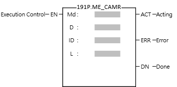
Operands Md: Mode D: Initial Cam Register ID: Cam Number L: Cam Resolution |
|||||||||||||||||||||||||||||||||||||||||||||||||||||||||||||||||||||||||||||||||||||||||||||
|
Relay and Register
|
||||||||||||||||||||||||||||||||||||||||||||||||||||||||||||||||||||||||||||||||||||||||||||||
|
Function Description |
||||||||||||||||||||||||||||||||||||||||||||||||||||||||||||||||||||||||||||||||||||||||||||||
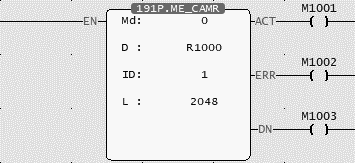
Md (Mode): 0 uses PLC Register , 1 gets data from the SD card D (Initial Cam Register): Md = 0 The initial address of the register to be stored after reading the Cam , Md = 1 SD card recipe file number ID (Cam Number): Cam number L (Cam Resolution): The length of the register to be stored after reading the Cam
When the execution control [EN] changes from 1→0, all output indications are reset
|
||||||||||||||||||||||||||||||||||||||||||||||||||||||||||||||||||||||||||||||||||||||||||||||
|
Program Example |
||||||||||||||||||||||||||||||||||||||||||||||||||||||||||||||||||||||||||||||||||||||||||||||
|
Ladder
|
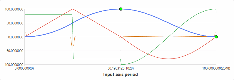
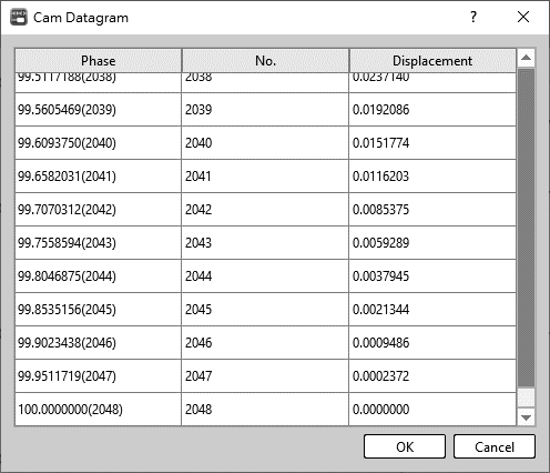
CAM
Datagram
|
|||||||||||||||||||||||||||||||||||||||||||||||||||||||||||||||||||||||||||||||||||||||||||||
|
||||||||||||||||||||||||||||||||||||||||||||||||||||||||||||||||||||||||||||||||||||||||||||||
6-1-7 Fun192 Write Motion Control Cam
|
Fun192 MFSysCAMW |
Write Motion Control Cam |
Fun192 MFSysCAMW |
||||||||||||||||||||||||||||||||||||||||||||||||||||||||||||||||||||||||||||||||||||||||||||
|
Symbol |
||||||||||||||||||||||||||||||||||||||||||||||||||||||||||||||||||||||||||||||||||||||||||||||
|
Ladder Symbol
|
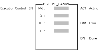
Operands Md: Mode D: C Initial am Address ID: Cam Number L: Cam Resolution |
|||||||||||||||||||||||||||||||||||||||||||||||||||||||||||||||||||||||||||||||||||||||||||||
|
Relay and Register
|
||||||||||||||||||||||||||||||||||||||||||||||||||||||||||||||||||||||||||||||||||||||||||||||
|
Function Description |
||||||||||||||||||||||||||||||||||||||||||||||||||||||||||||||||||||||||||||||||||||||||||||||
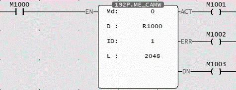
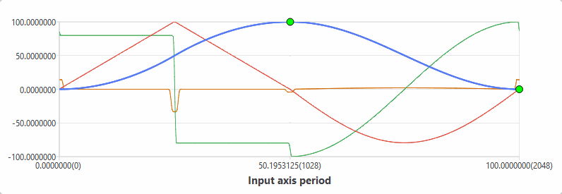
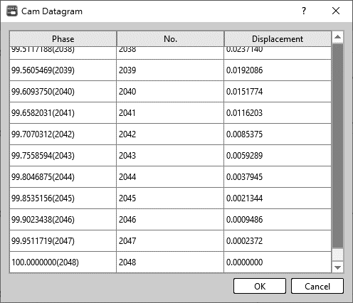
Md (Mode): 0 use PLC register , 1 gets data from the SD card D (Initial Cam Register): Md = 0 Write the initial address of the initial register of the cam , Md = 1 SD card recipe file number ID (Cam Number): Cam number L (Cam Resolution): The initial length of the register written to the cam
When the execution control [EN] changes from 1→0, all output indications are reset.
|
||||||||||||||||||||||||||||||||||||||||||||||||||||||||||||||||||||||||||||||||||||||||||||||
|
Program Example |
||||||||||||||||||||||||||||||||||||||||||||||||||||||||||||||||||||||||||||||||||||||||||||||
|
Ladder
|
CAM
Datagram
|
|||||||||||||||||||||||||||||||||||||||||||||||||||||||||||||||||||||||||||||||||||||||||||||
|
||||||||||||||||||||||||||||||||||||||||||||||||||||||||||||||||||||||||||||||||||||||||||||||
6-1-8 Fun196 Generate Cam (MFSysCAMGen)
|
Fun196 D MFSysCAMGen |
Generate Cam |
Fun196 D MFSysCAMGen |
||||||||||||||||||||||||||||||||||||||||||||||||||||||||||||||||||||||||||||||||||||||||||||
|
Command Description |
||||||||||||||||||||||||||||||||||||||||||||||||||||||||||||||||||||||||||||||||||||||||||||||
|
Ladder Symbol
|
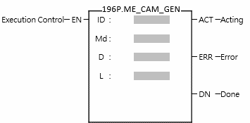
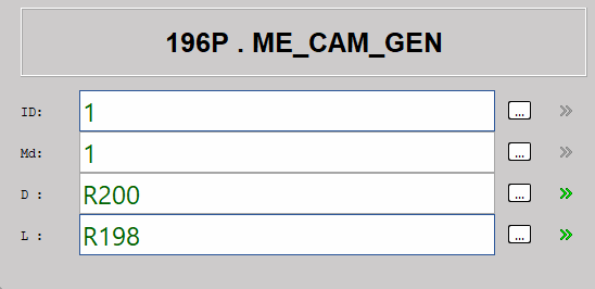
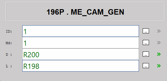
Operands ID: Cam No. Md: Cam Generating Mode D: Register Starting Address L: Cam Curve Stage No. |
|||||||||||||||||||||||||||||||||||||||||||||||||||||||||||||||||||||||||||||||||||||||||||||
|
Relay and Register
|
||||||||||||||||||||||||||||||||||||||||||||||||||||||||||||||||||||||||||||||||||||||||||||||
|
Function Description |
||||||||||||||||||||||||||||||||||||||||||||||||||||||||||||||||||||||||||||||||||||||||||||||
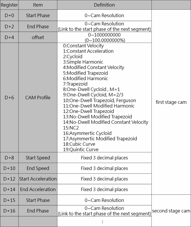
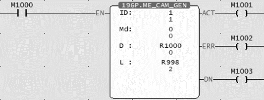
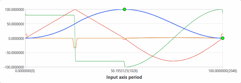
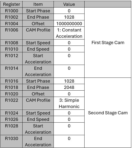
ID (Cam No.): 1-16 Md (Cam Generating Mode): 0 same as the cam table, 2 (Under development) D (Register Starting Address): Set starting register of the Cam L (Cam Curve Stage No.): Only Mode 0 has the setting of each stage of the Cam, and other modes do not need to be set.
When the execution control [EN] changes from 1→0, all output indications are reset.
|
||||||||||||||||||||||||||||||||||||||||||||||||||||||||||||||||||||||||||||||||||||||||||||||
|
Mode 0
|
||||||||||||||||||||||||||||||||||||||||||||||||||||||||||||||||||||||||||||||||||||||||||||||
|
Program Example |
||||||||||||||||||||||||||||||||||||||||||||||||||||||||||||||||||||||||||||||||||||||||||||||
|
Ladder
CAM
CAM Parameters
|
D
|
|||||||||||||||||||||||||||||||||||||||||||||||||||||||||||||||||||||||||||||||||||||||||||||
|
||||||||||||||||||||||||||||||||||||||||||||||||||||||||||||||||||||||||||||||||||||||||||||||

|
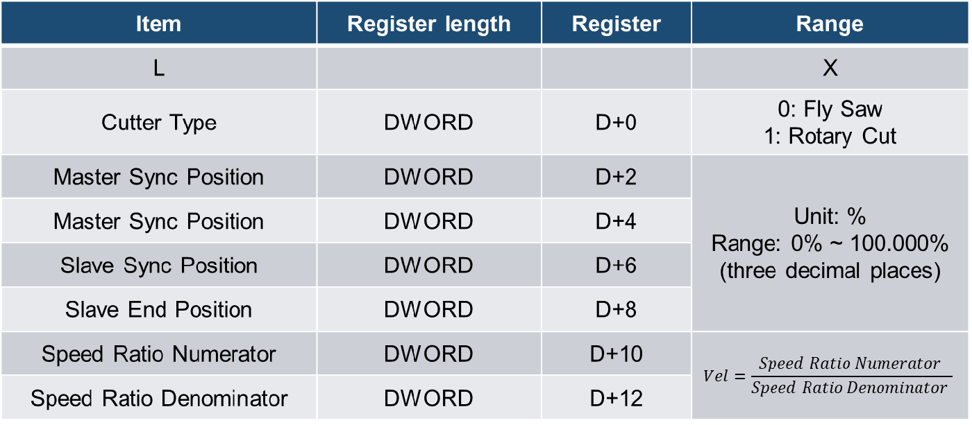
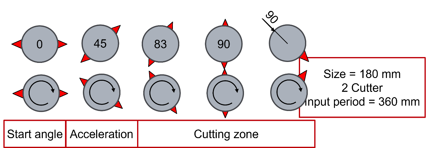
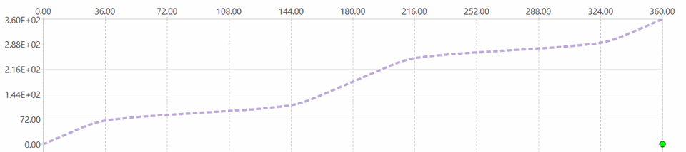
Mode 1 Type 0:Fly Saw / 1:Rotary Cut
Speed Ratio Denominator:input "Cam stroke"
|
|
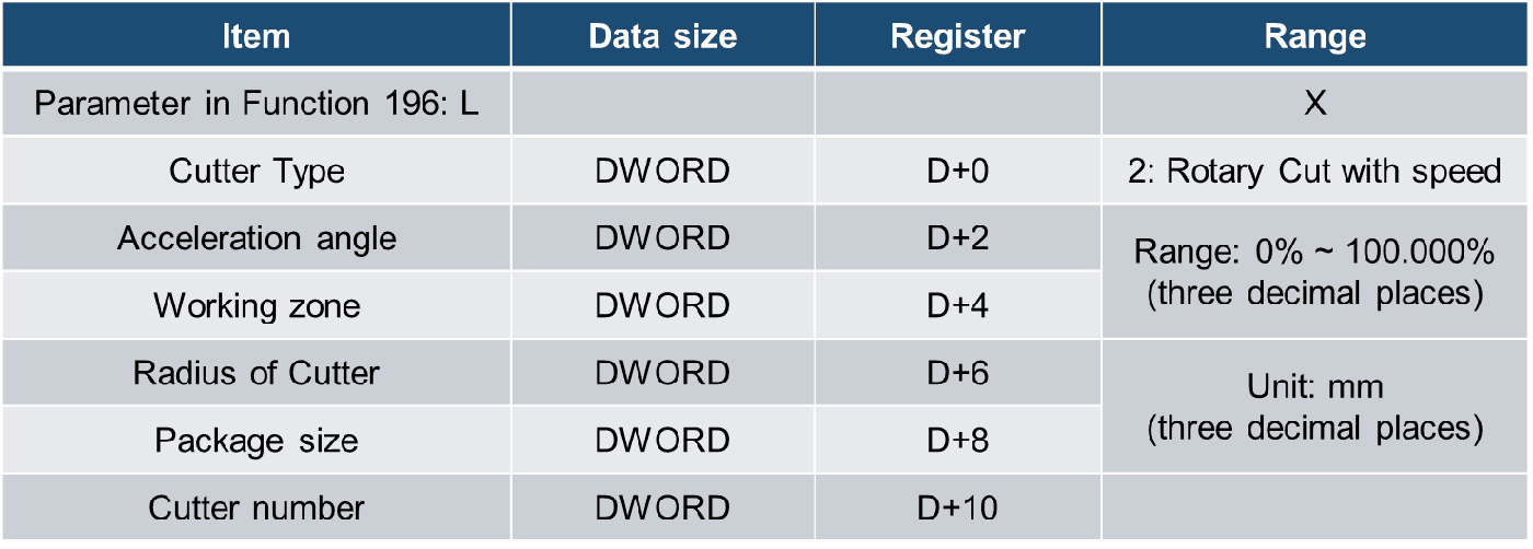
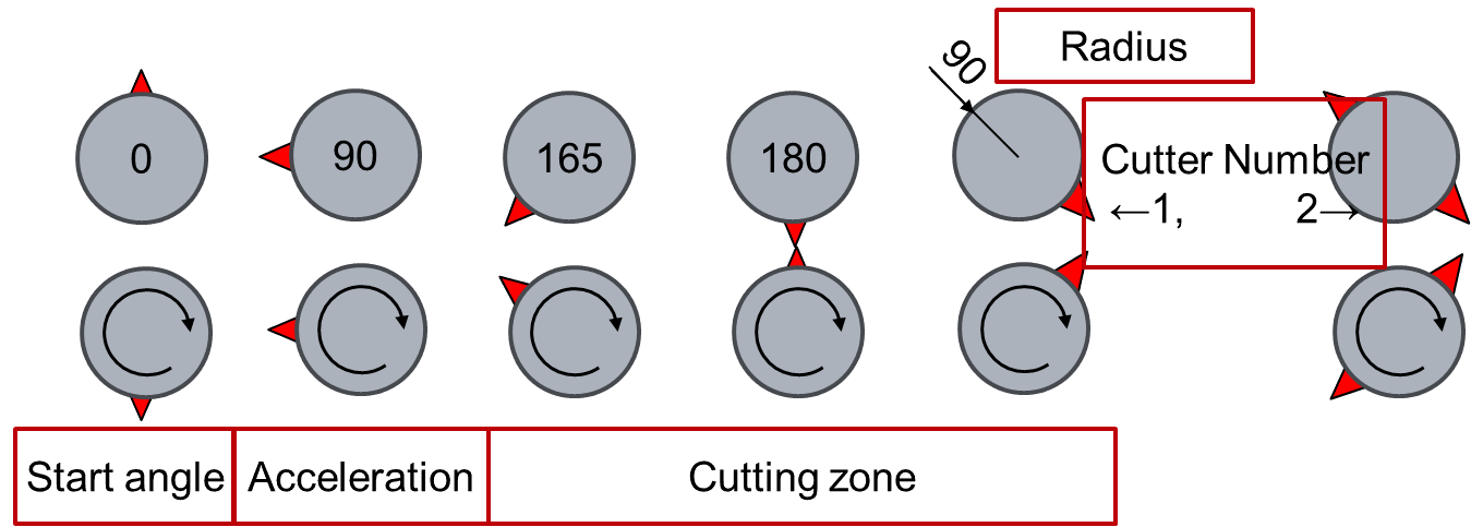
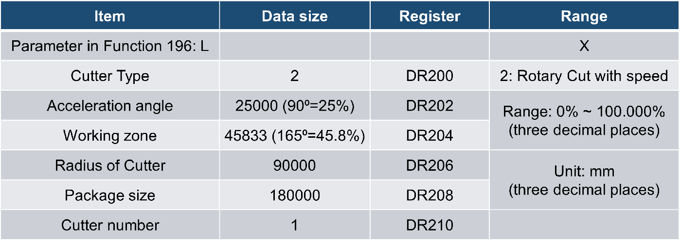
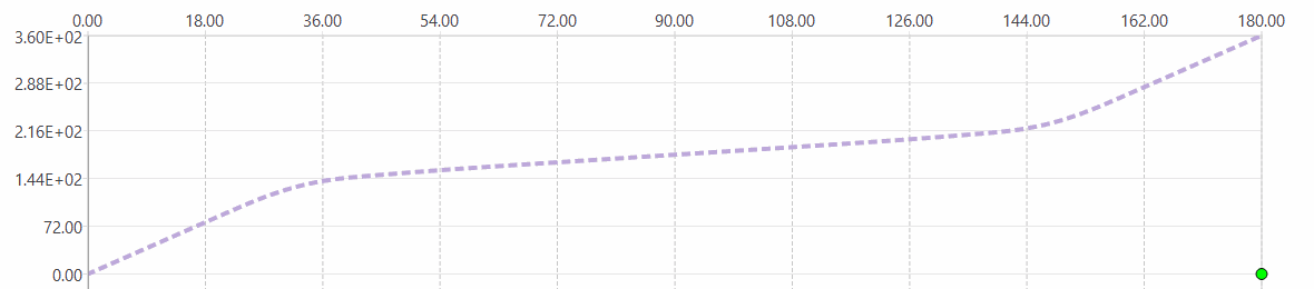
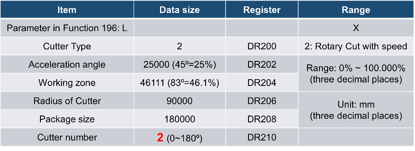
Mode 1 Type 2:Rotary Cut with initial speed
|
||
|
Program Example |
||
|
Ladder
D (Cutter Number:1)
Input period (mm)
|
||
D (Cutter Number:2)
Input period (mm) |
||
|
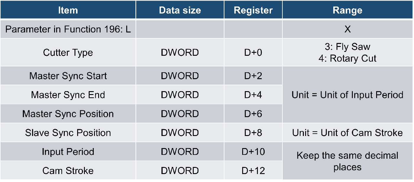
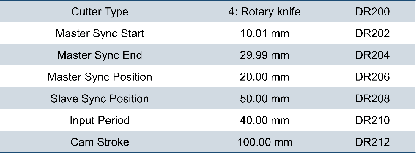
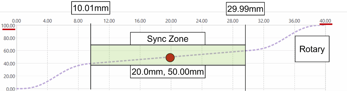
Mode1 Type 3:Specific point of sync Fly Saw / 4:Specific point of sync Rotary Cut
|
|
|
Program Example |
|
|
Ladder
D
Input period (mm)
|
|
|
|
6-1-9 Fun235 Set Axis to Virtual (MFSysSetVirt)
|
Fun235 P MFSysSetVirt |
Set Axis to Virtual |
Fun235 P MFSysSetVirt |
|||||||||||||||||||||||||||||||||||||||||||||||
|
Command Description |
|||||||||||||||||||||||||||||||||||||||||||||||||
|
Ladder Symbol
|
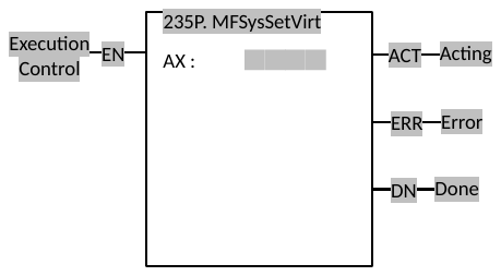
Operands AX : Axis Number |
||||||||||||||||||||||||||||||||||||||||||||||||
|
Relay and Register
|
|||||||||||||||||||||||||||||||||||||||||||||||||
|
Function Description |
|||||||||||||||||||||||||||||||||||||||||||||||||
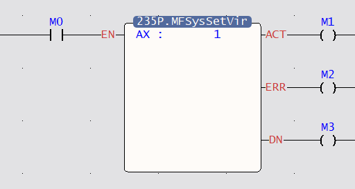
AX : The Axis number that will be convert to virtual axis. Range: 1~16
|
|||||||||||||||||||||||||||||||||||||||||||||||||
|
Program Example |
|||||||||||||||||||||||||||||||||||||||||||||||||
|
Ladder
|
|||||||||||||||||||||||||||||||||||||||||||||||||
|
|||||||||||||||||||||||||||||||||||||||||||||||||
7
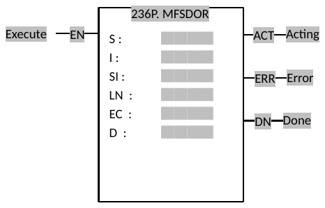
6-1-10 Fun236 EtherCAT SDO Read (MFSDOR)
|
Fun236 P MFSDOR |
EtherCAT SDO Read |
Fun236 P MFSDOR |
||||||||||||||||||||||||||||||||||||||||||||||||||||||||||||||||||||||||||||||||||||||||||||||||||||||||||||||||||||||||||
|
Command Description |
||||||||||||||||||||||||||||||||||||||||||||||||||||||||||||||||||||||||||||||||||||||||||||||||||||||||||||||||||||||||||||
|
Ladder Symbol
|
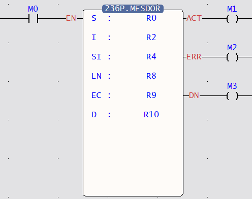
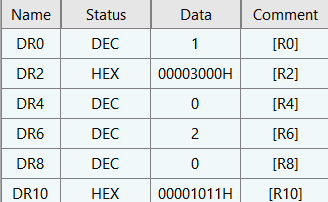
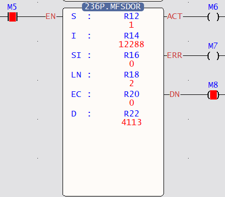
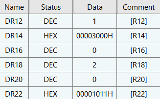
Operands S : Slave Number I : Index SI : Sub-index LN : Length EC : Register for error code D : Data Register (DWORD) |
|||||||||||||||||||||||||||||||||||||||||||||||||||||||||||||||||||||||||||||||||||||||||||||||||||||||||||||||||||||||||||
|
Relay and Register
|
||||||||||||||||||||||||||||||||||||||||||||||||||||||||||||||||||||||||||||||||||||||||||||||||||||||||||||||||||||||||||||
|
Function Description |
||||||||||||||||||||||||||||||||||||||||||||||||||||||||||||||||||||||||||||||||||||||||||||||||||||||||||||||||||||||||||||
S : Slave Number in EtherCAT I : Index of parameter in slave memory SI : Sub-index of parameter in slave memory LN : Length of the parameter EC : Register for error code D : Data Register (DWORD)
|
||||||||||||||||||||||||||||||||||||||||||||||||||||||||||||||||||||||||||||||||||||||||||||||||||||||||||||||||||||||||||||
|
Program Example |
||||||||||||||||||||||||||||||||||||||||||||||||||||||||||||||||||||||||||||||||||||||||||||||||||||||||||||||||||||||||||||
|
Ladder
|
||||||||||||||||||||||||||||||||||||||||||||||||||||||||||||||||||||||||||||||||||||||||||||||||||||||||||||||||||||||||||||
|
||||||||||||||||||||||||||||||||||||||||||||||||||||||||||||||||||||||||||||||||||||||||||||||||||||||||||||||||||||||||||||
6-1-11 Fun237 EtherCAT SDO Write (MFSDOW)
|
Fun237 P MFSDOW |
EtherCAT SDO Write |
Fun237 P MFSDOW |
||||||||||||||||||||||||||||||||||||||||||||||||||||||||||||||||||||||||||||||||||||||||||||||||||||||||||||||||||||||||||
|
Command Description |
||||||||||||||||||||||||||||||||||||||||||||||||||||||||||||||||||||||||||||||||||||||||||||||||||||||||||||||||||||||||||||
|
Ladder Symbol
|
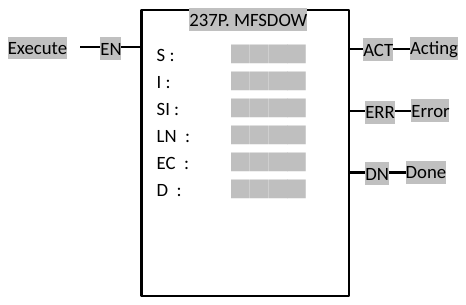
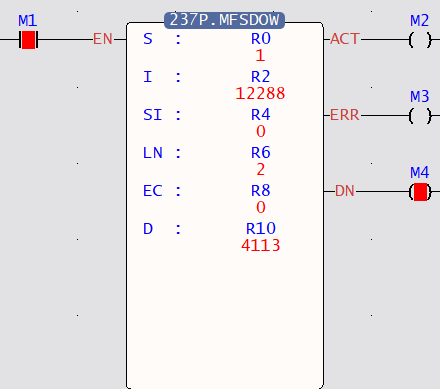
Operands S : Slave Number I : Index SI : Sub-index LN : Length EC : Register for error code D : Data Register (DWORD) |
|||||||||||||||||||||||||||||||||||||||||||||||||||||||||||||||||||||||||||||||||||||||||||||||||||||||||||||||||||||||||||
|
Relay and Register
|
||||||||||||||||||||||||||||||||||||||||||||||||||||||||||||||||||||||||||||||||||||||||||||||||||||||||||||||||||||||||||||
|
Function Description |
||||||||||||||||||||||||||||||||||||||||||||||||||||||||||||||||||||||||||||||||||||||||||||||||||||||||||||||||||||||||||||
S : Slave Number in EtherCAT I : Index of parameter in slave memory SI : Sub-index of parameter in slave memory LN : Length of the parameter EC : Register for error code D : Data Register (DWORD)
|
||||||||||||||||||||||||||||||||||||||||||||||||||||||||||||||||||||||||||||||||||||||||||||||||||||||||||||||||||||||||||||
|
Program Example |
||||||||||||||||||||||||||||||||||||||||||||||||||||||||||||||||||||||||||||||||||||||||||||||||||||||||||||||||||||||||||||
|
Ladder
|
||||||||||||||||||||||||||||||||||||||||||||||||||||||||||||||||||||||||||||||||||||||||||||||||||||||||||||||||||||||||||||
|
||||||||||||||||||||||||||||||||||||||||||||||||||||||||||||||||||||||||||||||||||||||||||||||||||||||||||||||||||||||||||||
6-2 Motion Control Parameter Mapping
6-2-1 Fun181 Change Motion Control Parameter
|
Fun181 MFChgTbPrm |
Change Motion Control Parameter |
Fun181 MFChgTbPrm |
||||||||||||||||||||||||||||||||||||||||||||||||||||||||
|
Command Description |
||||||||||||||||||||||||||||||||||||||||||||||||||||||||||
|
Ladder Symbol
|
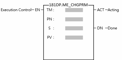
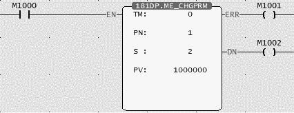
Operand TM: Table Number PN: Point Number S: Item Number PV: Written Value |
|||||||||||||||||||||||||||||||||||||||||||||||||||||||||
|
Relay and Register
|
||||||||||||||||||||||||||||||||||||||||||||||||||||||||||
|
Function Description |
||||||||||||||||||||||||||||||||||||||||||||||||||||||||||
TM (Table Number): 0 Point Table, 1 Axis Table, 2 Synchronous Table, 128 Flow Table PN (Point Number): According to the table to be modified by TM, it corresponds to different types of numbers, such as Point Table Number, Axis Number, and Flow Block Number. S (Item Number): Please refer to the table below. PV (Written Value): The value to write, with fixed Double Word.
|
||||||||||||||||||||||||||||||||||||||||||||||||||||||||||
|
Program Example |
||||||||||||||||||||||||||||||||||||||||||||||||||||||||||
|
Ladder
|
||||||||||||||||||||||||||||||||||||||||||||||||||||||||||
|
||||||||||||||||||||||||||||||||||||||||||||||||||||||||||
Fun181 Parameter Table
|
TM |
PN |
S |
PV Type |
||||
|
0 |
Motion Point Table |
1-1024 |
Point Table No. |
0 |
Operantion Mode |
16Bit |
UINT |
|
1 |
Acceleration Curve Type |
16Bit |
UINT |
||||
|
2 |
Master Axis Coordinates |
32Bit |
INT |
||||
|
3 |
Interpolation Axis 1 Coordinates |
32Bit |
INT |
||||
|
4 |
Interpolation Axis 2 Coordinates |
32Bit |
INT |
||||
|
5 |
Interpolation Axis 3 Coordinates |
32Bit |
INT |
||||
|
6 |
Speed |
32Bit |
UINT |
||||
|
7 |
Accelearation |
32Bit |
UINT |
||||
|
8 |
Deceleration |
32Bit |
UINT |
||||
|
9 |
S Acceleration Percentage |
16Bit |
UINT |
||||
|
10 |
S Deceleration Percentage |
16Bit |
UINT |
||||
|
11 |
Arc Mode |
16Bit |
UINT |
||||
|
12 |
Arc Direction |
16Bit |
UINT |
||||
|
13 |
Arc X Coordinate |
32Bit |
INT |
||||
|
14 |
Arc Y Coordinate |
32Bit |
INT |
||||
|
15 |
Arc Radius |
32Bit |
UINT |
||||
|
16 |
Auxiliary Arc Radius |
32Bit |
UINT |
||||
|
17 |
Waiting Time |
32Bit |
UINT |
||||
|
18 |
Next Point No. |
16Bit |
UINT |
||||
|
19 |
Revolution No. |
16Bit |
UINT |
||||
|
20 |
Consecutive Point Mode |
16Bit |
UINT |
||||
|
21 |
Arc Z Coordinate |
32Bit |
INT |
||||
|
22 |
3D Consecutive Point Percentage |
16Bit |
UINT |
||||
|
1 |
Motion Axis Table |
1-16 |
Axis No. |
0 |
Start Speed |
32Bit |
UINT |
|
1 |
Max. Rotating Speed |
32Bit |
UINT |
||||
|
2 |
Default Acceleration |
32Bit |
UINT |
||||
|
3 |
Default Ceceleration |
32Bit |
UINT |
||||
|
4 |
Soft Limit(+) |
32Bit |
INT |
||||
|
5 |
Soft Limit(-) |
32Bit |
INT |
||||
|
6 |
Following Error Window |
32Bit |
UINT |
||||
|
7 |
Following Error Timeout |
32Bit |
UINT |
||||
|
8 |
Pos Done Tolerance |
32Bit |
UINT |
||||
|
9 |
Pos Done Check Time |
32Bit |
UINT |
||||
|
10 |
Maximum Motor Torque |
16Bit |
UINT |
||||
|
11 |
Maximum Torque Limit(+) |
16Bit |
UINT |
||||
|
12 |
Maximum Torque Limit(-) |
16Bit |
UINT |
||||
|
13 |
HOME Return Mode |
16Bit |
UINT |
||||
|
14 |
HOME Return Direction |
16Bit |
UINT |
||||
|
15 |
HOME Return Movement |
32Bit |
INT |
||||
|
16 |
Home Return Speed |
32Bit |
UINT |
||||
|
17 |
HOME Return Crawl Speed |
32Bit |
UINT |
||||
|
18 |
JOG Initial Speed |
32Bit |
UINT |
||||
|
19 |
JOG Speed |
32Bit |
UINT |
||||
|
20 |
JOG Acceleration |
32Bit |
UINT |
||||
|
21 |
JOG Deceleration |
32Bit |
UINT |
||||
|
22 |
JOG Distannce |
32Bit |
UINT |
||||
|
2 |
Synchronous Parameter Table |
1-16 |
Axis No. |
0 |
Sync OFF time at deceleration stop |
32Bit |
UINT |
|
1 |
Master Axis compensation change mode |
32Bit |
INT |
||||
|
2 |
Master Axis compensation change time |
16Bit |
UINT |
||||
|
3 |
Aux Axis compensation command value |
32Bit |
UINT |
||||
|
4 |
Aux Axis compensation change mode |
32Bit |
INT |
||||
|
5 |
Aux Axis compensation change time |
16Bit |
UINT |
||||
|
6 |
Master Axis compensation change mode |
32Bit |
UINT |
||||
|
7 |
Variable gear retio numerator |
32Bit |
INT |
||||
|
8 |
Variable gear retio denominator |
32Bit |
INT |
||||
|
9 |
Gear retio change mode |
16Bit |
UINT |
||||
|
10 |
Variable gear retio change time |
32Bit |
UINT |
||||
|
11 |
Main clutch ON setting value |
32Bit |
UINT |
||||
|
12 |
Main clutch ON delay |
32Bit |
INT |
||||
|
13 |
Main clutch ON sliding curve |
32Bit |
INT |
||||
|
14 |
Main clutch ON sliding time |
32Bit |
UINT |
||||
|
15 |
Main clutch ON following time |
32Bit |
UINT |
||||
|
16 |
Main clutch ON follow-ups |
32Bit |
INT |
||||
|
17 |
Main clutch OFF setting value |
32Bit |
UINT |
||||
|
18 |
Main clutch OFF delay |
32Bit |
INT |
||||
|
19 |
Main clutch OFF sliding curve |
32Bit |
INT |
||||
|
20 |
Main clutch OFF sliding time |
32Bit |
UINT |
||||
|
21 |
Aux clutch ON setting value |
32Bit |
UINT |
||||
|
22 |
Aux clutch ON delay |
32Bit |
INT |
||||
|
23 |
Aux clutch ON sliding curve |
32Bit |
INT |
||||
|
24 |
Aux clutch ON sliding time |
32Bit |
UINT |
||||
|
25 |
Aux clutch ON following time |
32Bit |
UINT |
||||
|
26 |
Aux clutch ON follow-ups |
32Bit |
INT |
||||
|
27 |
Aux clutch OFF setting value |
32Bit |
UINT |
||||
|
28 |
Aux clutch OFF delay |
32Bit |
INT |
||||
|
29 |
Aux clutch OFF sliding curve |
32Bit |
INT |
||||
|
30 |
Aux clutch OFF sliding time |
32Bit |
UINT |
||||
|
31 |
Reserve |
||||||
|
32 |
Reserve |
||||||
|
33 |
Step Angle Compensation Base speed |
32Bit |
UINT |
||||
|
34 |
Step Angle Compensation Base value |
32Bit |
INT |
||||
|
35 |
Step Angle Compensation value change mode |
16Bit |
UINT |
||||
|
36 |
Step Angle Compensation value change time |
32Bit |
UINT |
||||
|
37 |
Eletronic Cam Number |
16Bit |
UINT |
||||
|
38 |
Sync contact output No. |
16Bit |
UINT |
||||
|
39 |
Filter Pulse Time |
32Bit |
UINT |
||||
|
40 |
Input Axis Cyclic |
32Bit |
UINT |
||||
|
41 |
Sync master axis phase default value |
32Bit |
UINT |
||||
|
42 |
Master axis phase default value after phase compensation |
32Bit |
UINT |
||||
|
43 |
Main clutch input axis phase default value |
32Bit |
UINT |
||||
|
44 |
Auxiliary clutch input axis phase default value |
32Bit |
UINT |
||||
|
45 |
Main clutch output axis phase default value |
32Bit |
UINT |
||||
|
46 |
Auxiliary clutch output axis phase default value |
32Bit |
UINT |
||||
|
47 |
Reserve |
||||||
|
48 |
Cam input axis phase default value |
32Bit |
UINT |
||||
|
49 |
Cam output axis base coordinate |
32Bit |
UINT |
||||
|
50 |
Cam stroke |
32Bit |
UINT |
||||
|
3 |
Reserve |
||||||
|
4 |
Axis Velocity Mode Parameter |
1-16 |
Axis No. |
0 |
Target Rotating Speed |
32Bit |
INT |
|
1 |
Torque Limit |
16Bit |
UINT |
||||
|
5 |
Axis Torque Mode Parameter |
1-16 |
Axis No. |
0 |
Target Torque |
16Bit |
INT |
|
1 |
Rotating Speed Limit |
32Bit |
UINT |
||||
|
128 |
Flow Table |
1-4096 |
Flow Block No. |
0 |
Modify Standby Time |
32Bit |
UINT |
|
116 |
Modify the positioning control block axis number |
32Bit |
INT |
||||
|
17 |
Modify the set speed value |
32Bit |
UINT |
||||
6-2-2 Fun198 Set Mapping Table (MFMapTbPrm)
|
Fun198 MFMapTbPrm |
Set Mapping Table |
Fun198 MFMapTbPrm |
||||||||||||||||||||||||||||||||||||||||||||||||||||||||||||||||||||||||||||||
|
Command Description |
||||||||||||||||||||||||||||||||||||||||||||||||||||||||||||||||||||||||||||||||
|
Ladder Symbol
|
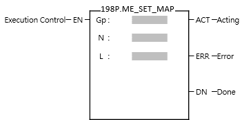
Operands Gp: Mapping Table Group No. N: Mapping Starting Table No. L: Consecutive Mapping Length |
|||||||||||||||||||||||||||||||||||||||||||||||||||||||||||||||||||||||||||||||
|
Relay and Register
|
||||||||||||||||||||||||||||||||||||||||||||||||||||||||||||||||||||||||||||||||
|
Function Description |
||||||||||||||||||||||||||||||||||||||||||||||||||||||||||||||||||||||||||||||||
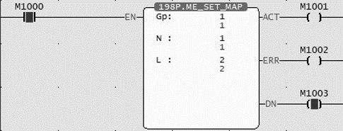
Gp (Mapping Table Groups No.): Group 1-16, 0 means all groups. N (Mapping Table Starting Table No.): Mapping table number 1-1024, 0 means the entire mapping table. L (Consecutive Mapping Length): Number of consecutive mapping items, 0 means mapping to the last item in the page.
When the execution control [EN] changes from 1→0, all output indications are reset.
|
||||||||||||||||||||||||||||||||||||||||||||||||||||||||||||||||||||||||||||||||
|
Program Example |
||||||||||||||||||||||||||||||||||||||||||||||||||||||||||||||||||||||||||||||||
|
Ladder
|
Mapping Table
Motion Axis Setting Table
|
|||||||||||||||||||||||||||||||||||||||||||||||||||||||||||||||||||||||||||||||
|
||||||||||||||||||||||||||||||||||||||||||||||||||||||||||||||||||||||||||||||||

6-3 Mode 1: Motion Flow Control
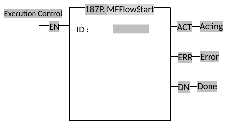
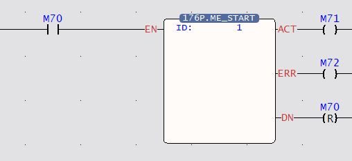
6-3-1 Fun176 Start Motion Flow (MFFlowStart)
|
Fun176 P MFFlowStart |
Start Motion Flow |
Fun176 P MFFlowStart |
|||||||||||||||||||||||||||||||||||||||||||||||
|
Command Description |
|||||||||||||||||||||||||||||||||||||||||||||||||
|
Ladder Symbol
|
Operand ID: Motion Flow ID |
||||||||||||||||||||||||||||||||||||||||||||||||
|
Relay and Register
|
|||||||||||||||||||||||||||||||||||||||||||||||||
|
Function Description |
|||||||||||||||||||||||||||||||||||||||||||||||||
|
Enable the Motion Flow with designated ID.
|
|||||||||||||||||||||||||||||||||||||||||||||||||
|
Program Example |
|||||||||||||||||||||||||||||||||||||||||||||||||
|
Ladder
|
|||||||||||||||||||||||||||||||||||||||||||||||||
|
|||||||||||||||||||||||||||||||||||||||||||||||||
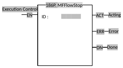
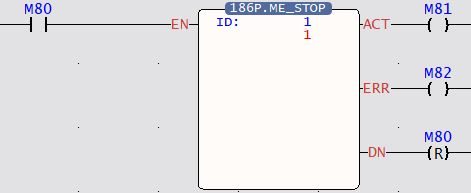
6-3-2 Fun186 Stop Motion Flow (MFFlowStop)
|
Fun186 P MFFlowStop |
Stop Motion Flow |
Fun186 P MFFlowStop |
|||||||||||||||||||||||||||||||||||||||||||||||
|
Command Description |
|||||||||||||||||||||||||||||||||||||||||||||||||
|
Ladder Symbol
|
Operand ID: Motion Flow ID |
||||||||||||||||||||||||||||||||||||||||||||||||
|
Relay and Register
|
|||||||||||||||||||||||||||||||||||||||||||||||||
|
Function Description |
|||||||||||||||||||||||||||||||||||||||||||||||||
|
Immediately stop the motion flow of the specified ID. When execution of this command is done, MFFlowResume cannot be used to resume execution. Need to use MFFlowStart to restart the process.
|
|||||||||||||||||||||||||||||||||||||||||||||||||
|
Program Example |
|||||||||||||||||||||||||||||||||||||||||||||||||
|
Ladder
|
|
||||||||||||||||||||||||||||||||||||||||||||||||
|
|||||||||||||||||||||||||||||||||||||||||||||||||
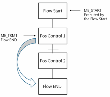
6-3-3 Fun182 Pause Motion Flow (MFFlowPause)
|
Fun182 P MFFlowPause |
Pause Motion Flow |
Fun182 P MFFlowPause |
||||||||||||||||||||||||||||||||||||||||||||||||
|
Command Description |
||||||||||||||||||||||||||||||||||||||||||||||||||
|
Ladder Symbol
|
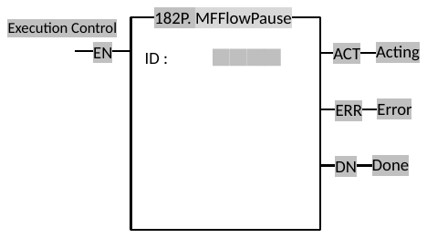
Operand ID: Motion Flow ID |
|||||||||||||||||||||||||||||||||||||||||||||||||
|
Relay and Register
|
||||||||||||||||||||||||||||||||||||||||||||||||||
|
Function Description |
||||||||||||||||||||||||||||||||||||||||||||||||||
|
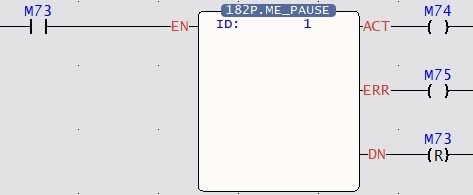
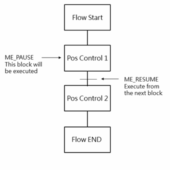
Pause the motion flow with specified ID, and stop after executing the current flow block; to resume the paused motion flow, execute “Fun183 MFFlowResume” function.
|
||||||||||||||||||||||||||||||||||||||||||||||||||
|
Program Example |
||||||||||||||||||||||||||||||||||||||||||||||||||
|
Ladder
|
|
|||||||||||||||||||||||||||||||||||||||||||||||||
|
||||||||||||||||||||||||||||||||||||||||||||||||||
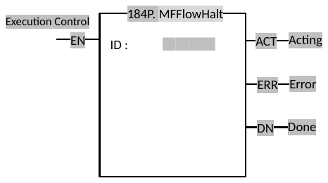
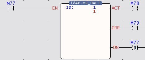
6-3-4 Fun184 Halt Motion Flow (MFFlowHalt)
|
Fun184 P MFFlowHalt |
Halt Motion Flow |
Fun184 P MFFlowHalt |
|||||||||||||||||||||||||||||||||||||||||||||||
|
Command Description |
|||||||||||||||||||||||||||||||||||||||||||||||||
|
Ladder Symbol
|
Operand ID: Motion Flow ID |
||||||||||||||||||||||||||||||||||||||||||||||||
|
Relay and Register
|
|||||||||||||||||||||||||||||||||||||||||||||||||
|
Function Description |
|||||||||||||||||||||||||||||||||||||||||||||||||
|
Immediately stop the currently executing process block; to continue the stopped motion flow, use “Fun183 MFFlowResume” to resume execution.
|
|||||||||||||||||||||||||||||||||||||||||||||||||
|
Program Example |
|||||||||||||||||||||||||||||||||||||||||||||||||
|
Ladder
|
|||||||||||||||||||||||||||||||||||||||||||||||||
|
|||||||||||||||||||||||||||||||||||||||||||||||||
6-3-5 Fun183 Resume Motion Flow (MFFlowResume)
|
Fun183 P MFFlowResume |
Resume Motion Flow |
Fun183 P MFFlowResume |
|||||||||||||||||||||||||||||||||||||||||||||||
|
Command Description |
|||||||||||||||||||||||||||||||||||||||||||||||||
|
Ladder Symbol
|
Operand ID: Motion Flow ID |
||||||||||||||||||||||||||||||||||||||||||||||||
|
Relay and Register
|
|||||||||||||||||||||||||||||||||||||||||||||||||
|
Function Description |
|||||||||||||||||||||||||||||||||||||||||||||||||
|
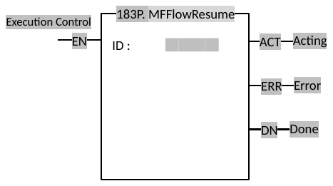
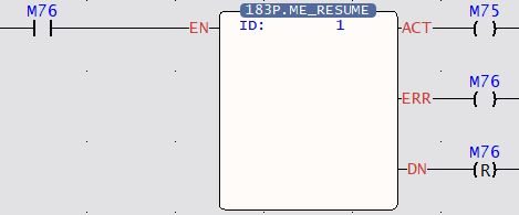
Resume and continue the execution of the paused or halted motion flow.
|
|||||||||||||||||||||||||||||||||||||||||||||||||
|
Program Example |
|||||||||||||||||||||||||||||||||||||||||||||||||
|
Ladder
|
|||||||||||||||||||||||||||||||||||||||||||||||||
|
|||||||||||||||||||||||||||||||||||||||||||||||||
6-4 Mode 2: Ladder Control
6-4-1 Fun179 Position Control (MFPointMov)
|
Fun179 P MFPointMov |
Position Control |
Fun179 P MFPointMov |
|||||||||||||||||||||||||||||||||||||||||||||||||||||||||||||||
|
Command Description |
|||||||||||||||||||||||||||||||||||||||||||||||||||||||||||||||||
|
Ladder Symbol
|
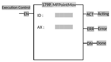
Operand PT : Point number of the executing position control point table AX : Master axis of the executing position control |
||||||||||||||||||||||||||||||||||||||||||||||||||||||||||||||||
|
Relay and Register
|
|||||||||||||||||||||||||||||||||||||||||||||||||||||||||||||||||
|
Function Description |
|||||||||||||||||||||||||||||||||||||||||||||||||||||||||||||||||
|
Execute the point table position control commands.
|
|||||||||||||||||||||||||||||||||||||||||||||||||||||||||||||||||
|
Program Example |
|||||||||||||||||||||||||||||||||||||||||||||||||||||||||||||||||
|
Ladder
|
|||||||||||||||||||||||||||||||||||||||||||||||||||||||||||||||||
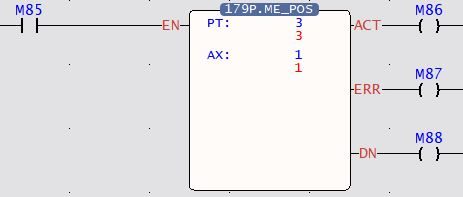
When PT = 1 and AX = 1, axis 1 will run according to the parameters in point table 1. However, if PT=2 and AX=1 are set, it will fail due to the difference from the point table setting, and ERR will be triggered.
|
|||||||||||||||||||||||||||||||||||||||||||||||||||||||||||||||||
6-4-2 Fun178 HOME Return (MFHome)
|
Fun178 P MFHome |
HOME Return |
Fun178 P MFHome |
||||||||||||||||||||||||||||||||||||||||||||||||
|---|---|---|---|---|---|---|---|---|---|---|---|---|---|---|---|---|---|---|---|---|---|---|---|---|---|---|---|---|---|---|---|---|---|---|---|---|---|---|---|---|---|---|---|---|---|---|---|---|---|---|
|
Command Description |
||||||||||||||||||||||||||||||||||||||||||||||||||
|
Ladder Symbol
|
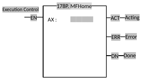
Operand AX : Axis to execute HOME Return |
|||||||||||||||||||||||||||||||||||||||||||||||||
|
Relay and Register
|
||||||||||||||||||||||||||||||||||||||||||||||||||
|
Function Description |
||||||||||||||||||||||||||||||||||||||||||||||||||
|
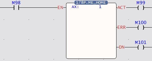
Specify a motion axis to execute HOME Return.
Special Register Axis 1: HOME Return is acting – M10621 Axis 1: HOME Return is done – M10622
|
||||||||||||||||||||||||||||||||||||||||||||||||||
|
Program Example |
||||||||||||||||||||||||||||||||||||||||||||||||||
|
Ladder
|
||||||||||||||||||||||||||||||||||||||||||||||||||
|
||||||||||||||||||||||||||||||||||||||||||||||||||
6-4-3 Fun180 JOG Control (MFJog)
|
Fun180 P MFJog |
JOG Control |
Fun180 P MFJog |
|||||||||||||||||||||||||||||||||||||||||||||||||||||||||||||||
|
Command Description |
|||||||||||||||||||||||||||||||||||||||||||||||||||||||||||||||||
|
Ladder Symbol
|
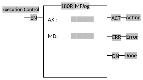
Operand AX : Axis to execute JOG control MD : Execution mode |
||||||||||||||||||||||||||||||||||||||||||||||||||||||||||||||||
|
Relay and Register
|
|||||||||||||||||||||||||||||||||||||||||||||||||||||||||||||||||
|
Function Description |
|||||||||||||||||||||||||||||||||||||||||||||||||||||||||||||||||
|
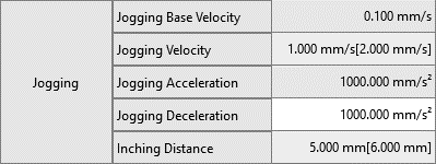
Specify a motion axis to execute JOG function according to JOG parameters and setting modes.
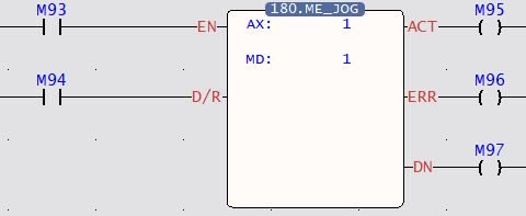
Mode 0 : Continue going at JOG initial speed. Mode 1 : Advance at the JOG initial speed, advance the JOG distance and then stop. Mode 2 : Start at the JOG initial speed, accelerate to the JOG speed with the JOG acceleration and continue moving forward。 Mode 3 : Start at the JOG initial speed, accelerate to the JOG speed with the JOG acceleration, and stop after moving forward with JOG distance.
|
|||||||||||||||||||||||||||||||||||||||||||||||||||||||||||||||||
|
Program Example |
|||||||||||||||||||||||||||||||||||||||||||||||||||||||||||||||||
|
Ladder
|
|||||||||||||||||||||||||||||||||||||||||||||||||||||||||||||||||
When AX = 1 and MD = 1, it means axis 1 will run a distance of 100mm at a speed of 1mm/s.
|
|||||||||||||||||||||||||||||||||||||||||||||||||||||||||||||||||
6-5 Mode 3: Ladder Direct Control
6-5-1 Fun193 EtherCAT Handwheel (MFGearMPG)
|
Fun193 D MFGearMPG |
EtherCAT Handwheel |
Fun193 D MFGearMPG |
|||||||||||||||||||||||||||||||||||||||||||||||||||||||||||||||||||||||||||||||||||||||||||||||||||||||||||
|
Command Description |
|||||||||||||||||||||||||||||||||||||||||||||||||||||||||||||||||||||||||||||||||||||||||||||||||||||||||||||
|
Ladder Symbol
|
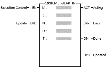
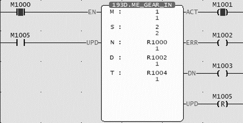
Operands M : Master Axis Input Source S: Slave Axis Output Target N: Variable Gear Ratio Numerator D: Variable Gear Ratio Denominator T: Transition Time (ms) |
||||||||||||||||||||||||||||||||||||||||||||||||||||||||||||||||||||||||||||||||||||||||||||||||||||||||||||
|
Relay and Register
|
|||||||||||||||||||||||||||||||||||||||||||||||||||||||||||||||||||||||||||||||||||||||||||||||||||||||||||||
|
Function Description |
|||||||||||||||||||||||||||||||||||||||||||||||||||||||||||||||||||||||||||||||||||||||||||||||||||||||||||||
M (Master Axis Input Source): EtherCAT_Axis Number 1-16 : Encoder_Gray Code 100 (X8-X15) : Encoder_Hardware High-speed Counter Number 101-108 ( HSC0~HSC7 ) S (Slave Axis Output Target): EtherCAT_Axis Number 1-16 ([M Master Input Source] cannot be the same as [S Slave Axis Output Target]) N (Variable Gear Ratio Numerator): Positive and negative numbers, including the [Decimal Point Position] of [Motion Axis Setting] in [Motion Control]. ([Axis unit] set mm, [Decimal point position] set 0.001, N: DR0 = 1000 is equal to 1.000mm) D (Variable Gear Ratio Denominator): Positive number (a real number greater than zero), including the [Decimal Point Position] of [Motion Axis Setting] in [Motion Control] T (Transition Time (ms)): Positive number (real number greater than zero), the unit is ms
|
|||||||||||||||||||||||||||||||||||||||||||||||||||||||||||||||||||||||||||||||||||||||||||||||||||||||||||||
|
Program Example |
|||||||||||||||||||||||||||||||||||||||||||||||||||||||||||||||||||||||||||||||||||||||||||||||||||||||||||||
|
Ladder
|
Axis Parameter Setting
|
||||||||||||||||||||||||||||||||||||||||||||||||||||||||||||||||||||||||||||||||||||||||||||||||||||||||||||
|
|||||||||||||||||||||||||||||||||||||||||||||||||||||||||||||||||||||||||||||||||||||||||||||||||||||||||||||
|
Ladder
|
|||||||||||||||||||||||||||||||||||||||||||||||||||||||||||||||||||||||||||||||||||||||||||||||||||||||||||||
|
|||||||||||||||||||||||||||||||||||||||||||||||||||||||||||||||||||||||||||||||||||||||||||||||||||||||||||||
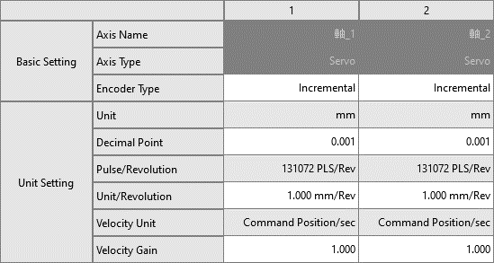
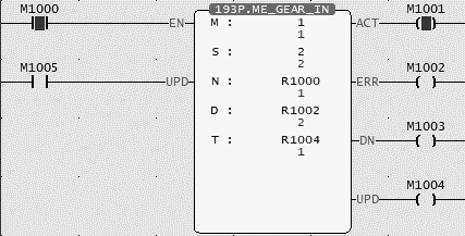
6-5-2 Fun194 Velocity Control (MFVelCtl)
|
Fun194 D MFVelCtl |
Velocity Control Mode |
Fun194 D MFVelCtl |
||||||||||||||||||||||||||||||||||||||||||||||||||||||||||||||||||||||||||||
|
Command Description |
||||||||||||||||||||||||||||||||||||||||||||||||||||||||||||||||||||||||||||||
|
Ladder Symbol
|
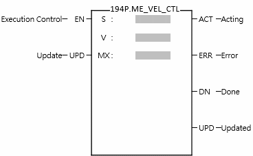
Operands S: EtherCAT Velocity Control Axis V: Velocity MX: Max. Torque Limit |
|||||||||||||||||||||||||||||||||||||||||||||||||||||||||||||||||||||||||||||
|
Relay and Register
|
||||||||||||||||||||||||||||||||||||||||||||||||||||||||||||||||||||||||||||||
|
Function Description |
||||||||||||||||||||||||||||||||||||||||||||||||||||||||||||||||||||||||||||||
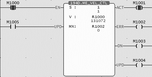
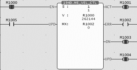
S (Speed Control Axis): EtherCAT_ Axis Number 1-16 V (Velocity): Setting velocity value, unit: Pulses/s MX (Maximum Torque Limit): The maximum torque limit when the speed cannot reach the speed setting value, 0 equals no limit, unit 0.0%
When the execution control [EN] changes from 1→0, Fun194 stops the axis velocity control and resets all output indications.
|
||||||||||||||||||||||||||||||||||||||||||||||||||||||||||||||||||||||||||||||
|
Program Example |
||||||||||||||||||||||||||||||||||||||||||||||||||||||||||||||||||||||||||||||
|
Ladder
|
||||||||||||||||||||||||||||||||||||||||||||||||||||||||||||||||||||||||||||||
|
||||||||||||||||||||||||||||||||||||||||||||||||||||||||||||||||||||||||||||||
|
Ladder
|
||||||||||||||||||||||||||||||||||||||||||||||||||||||||||||||||||||||||||||||
|
||||||||||||||||||||||||||||||||||||||||||||||||||||||||||||||||||||||||||||||
6-5-3 Fun195 Torque Control (MFTorqCtl)
|
Fun195 D MFTorqCtl |
Torque Control Mode |
Fun195 D MFTorqCtl |
|||||||||||||||||||||||||||||||||||||||||||||||||||||||||||||||||||||||||||||
|
Command Description |
|||||||||||||||||||||||||||||||||||||||||||||||||||||||||||||||||||||||||||||||
|
Ladder Symbol
|
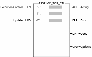
Operands S: EtherCAT Torque Control Axis T: Set Torque MX: Max. Speed Limit |
||||||||||||||||||||||||||||||||||||||||||||||||||||||||||||||||||||||||||||||
|
Relay and Register
|
|||||||||||||||||||||||||||||||||||||||||||||||||||||||||||||||||||||||||||||||
|
Function Description |
|||||||||||||||||||||||||||||||||||||||||||||||||||||||||||||||||||||||||||||||
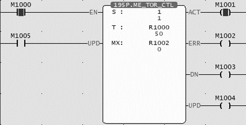
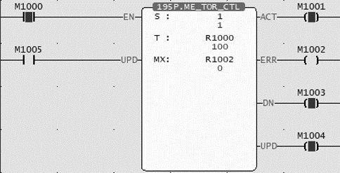
S (Torque Control Axis): EtherCAT_ Axis Number 1-16 T (Torque): Torque setting value, unit: 0.0% MX (Maximum Speed Limit): The maximum speed limit when the torque cannot reach the torque setting value, 0 equals no limit, the unit is rpm.
When the execution control [EN] changes from 1→0, Fun195 stops the axis torque control and resets all output indications.
|
|||||||||||||||||||||||||||||||||||||||||||||||||||||||||||||||||||||||||||||||
|
Program Example |
|||||||||||||||||||||||||||||||||||||||||||||||||||||||||||||||||||||||||||||||
|
Ladder
|
|||||||||||||||||||||||||||||||||||||||||||||||||||||||||||||||||||||||||||||||
|
|||||||||||||||||||||||||||||||||||||||||||||||||||||||||||||||||||||||||||||||
|
Ladder
|
|||||||||||||||||||||||||||||||||||||||||||||||||||||||||||||||||||||||||||||||
|
|||||||||||||||||||||||||||||||||||||||||||||||||||||||||||||||||||||||||||||||
6-5-4 Fun197 Single Axis Positioning(MFAxMov)
|
Fun197 D P MFAxMov |
Single Axis Positioning |
Fun197 D P MFAxMov |
||||||||||||||||||||||||||||||||||||||||||||||||||||||||||||||||||||||||||||||||||||||||||||||||||||||||||||||||||||||||||||||||||||||||||||||||||||||||||||||||||||||||||||||||||||||
|
Command Description |
||||||||||||||||||||||||||||||||||||||||||||||||||||||||||||||||||||||||||||||||||||||||||||||||||||||||||||||||||||||||||||||||||||||||||||||||||||||||||||||||||||||||||||||||||||||||
|
Ladder Symbol
|
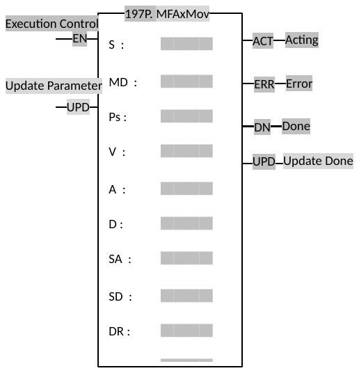
Operands S: EtherCAT Control Axis MD: Opearating Mode PS: Target Position V: Velocity A: Acceleration D: Deceleration SA: S Acceleration Curve % SD: S Deceleration Curve % DR: Direction BF: Consecutive Velocity Mode |
|||||||||||||||||||||||||||||||||||||||||||||||||||||||||||||||||||||||||||||||||||||||||||||||||||||||||||||||||||||||||||||||||||||||||||||||||||||||||||||||||||||||||||||||||||||||
|
Relay and Register
|
||||||||||||||||||||||||||||||||||||||||||||||||||||||||||||||||||||||||||||||||||||||||||||||||||||||||||||||||||||||||||||||||||||||||||||||||||||||||||||||||||||||||||||||||||||||||
|
Function Description |
||||||||||||||||||||||||||||||||||||||||||||||||||||||||||||||||||||||||||||||||||||||||||||||||||||||||||||||||||||||||||||||||||||||||||||||||||||||||||||||||||||||||||||||||||||||||
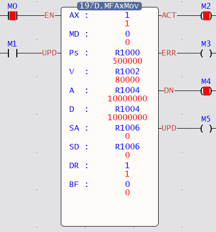
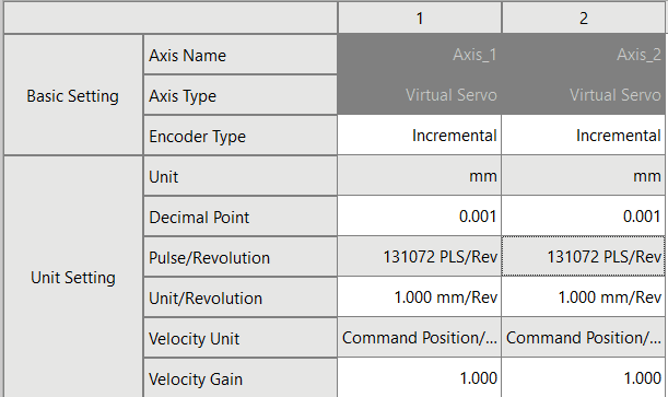
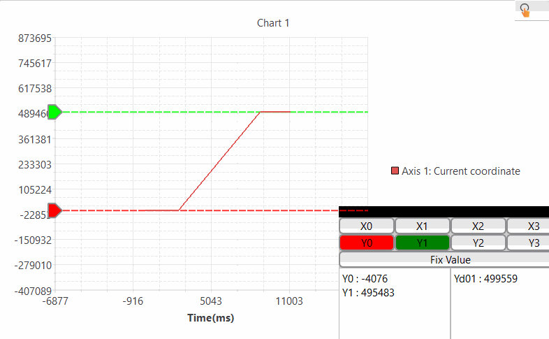
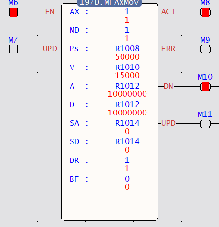
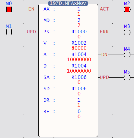
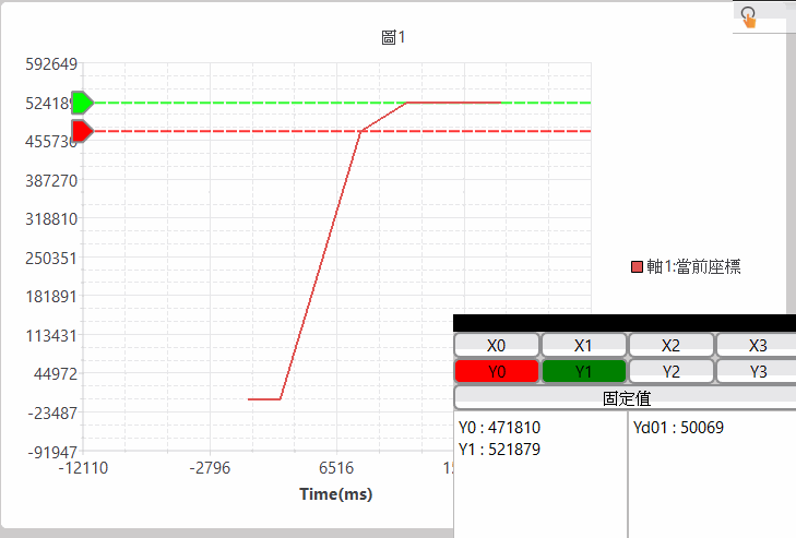
S (EtherCAT Control Axis): EtherCAT_Axis No.1-16 MD (Operating Mode): 0 Absolute, 1 Relative, 2 Infinite distance mode PS )Target Position): Positive and negative numbers, including the [Decimal Point Position] of the [Motion Axis Setting] in [Motion Control]. ([Axis Unit]: mm, [Decimal Point Position]: 0.001, PS: DR0 = 1000 is equal to 1.000mm) V (Velocity): Positive number (a real number greater than zero), including the [Decimal Point Position] of the [Motion Axis Setting] in [Motion Control]. A (Acceleration): Positive number (a real number greater than zero), including the [Decimal Point Position] of the [Motion Axis Setting] in [Motion Control]. D (Deceleration): Positive number (a real number greater than zero), including the [Decimal Point Position] of the [Motion Axis Setting] in [Motion Control]. SA (S Acceleration Curve %): Positive integer, 0-1000 ‰ SD (S Deceleration Curve %): Positive integer, 0-1000 ‰ DR (Direction): 1 positive direction, 2 negative direction BF(Consecutive Velocity Mode): 0 executes the current command immediately, 1 waits for the end of the previous command, 2 selects the lower consecutive speed, 3 selects the previous consecutive command speed, 4 selects the current consecutive command speed, 5 selects the higher consecutive speed.
When the execution control [EN] is triggered by the lower differential, Fun197 stops the axis position control and resets all output indications.
|
||||||||||||||||||||||||||||||||||||||||||||||||||||||||||||||||||||||||||||||||||||||||||||||||||||||||||||||||||||||||||||||||||||||||||||||||||||||||||||||||||||||||||||||||||||||||
|
Program Example |
||||||||||||||||||||||||||||||||||||||||||||||||||||||||||||||||||||||||||||||||||||||||||||||||||||||||||||||||||||||||||||||||||||||||||||||||||||||||||||||||||||||||||||||||||||||||
|
Ladder
|
Axis Parameter Setting
|
|||||||||||||||||||||||||||||||||||||||||||||||||||||||||||||||||||||||||||||||||||||||||||||||||||||||||||||||||||||||||||||||||||||||||||||||||||||||||||||||||||||||||||||||||||||||
|
||||||||||||||||||||||||||||||||||||||||||||||||||||||||||||||||||||||||||||||||||||||||||||||||||||||||||||||||||||||||||||||||||||||||||||||||||||||||||||||||||||||||||||||||||||||||
|
|
||||||||||||||||||||||||||||||||||||||||||||||||||||||||||||||||||||||||||||||||||||||||||||||||||||||||||||||||||||||||||||||||||||||||||||||||||||||||||||||||||||||||||||||||||||||||
 Interrupt Constant Feed
6-5-5 Fun238 Linear Interpolation (MFAxLMov)
|
Fun238 D P MFAxLMov |
Linear Interpolation |
Fun238 D P MFAxLMov |
||||||||||||||||||||||||||||||||||||||||||||||||||||||||||||||||||||||||||||||||||||||||||||||||||||||||||||||||||||||||||
|
Command Description |
||||||||||||||||||||||||||||||||||||||||||||||||||||||||||||||||||||||||||||||||||||||||||||||||||||||||||||||||||||||||||||
|
Ladder Symbol
|
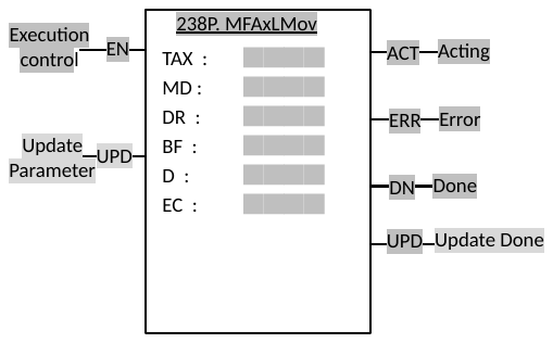
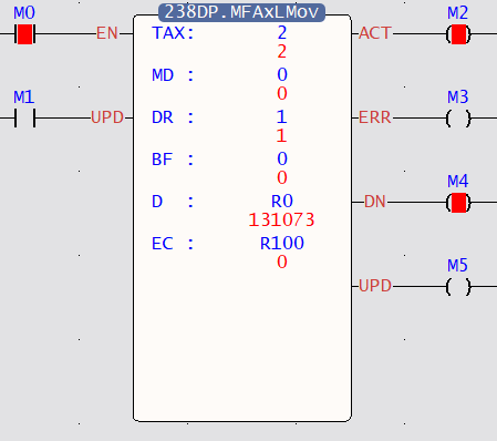
Operands TAX : Total Axis Number MD : Operation Mode DR : Direction BF : Continuous Mode D : Parameter Register Start Address EC : Register for Error code |
|||||||||||||||||||||||||||||||||||||||||||||||||||||||||||||||||||||||||||||||||||||||||||||||||||||||||||||||||||||||||||
|
Relay and Register
|
||||||||||||||||||||||||||||||||||||||||||||||||||||||||||||||||||||||||||||||||||||||||||||||||||||||||||||||||||||||||||||
|
Function Description |
||||||||||||||||||||||||||||||||||||||||||||||||||||||||||||||||||||||||||||||||||||||||||||||||||||||||||||||||||||||||||||
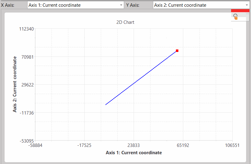
TAX (Total Axis Number) : Axes number in movement – 1 ~ 4 MD (Operation Mode) : 0 – Absolute Positioning, 1 – Relative Positioning. DR (Direction) : 1 – Positive, 2 – Negative. BF (Continuous Mode) : 0: Stop Current Movement 1: Wait Current Mov Finish 2: Continue with Lower Speed 3: Continue with Current Speed 4: Continue with New Speed 5: Continue with higher Speed D : First Register Address of Data. EC : Register for Error Code.
When execution control (EN) is triggered in lower edge, the Fun238 will be stopped, and all the coils will be reset.
Motion data in parameter D:
|
||||||||||||||||||||||||||||||||||||||||||||||||||||||||||||||||||||||||||||||||||||||||||||||||||||||||||||||||||||||||||||
|
Program Example |
||||||||||||||||||||||||||||||||||||||||||||||||||||||||||||||||||||||||||||||||||||||||||||||||||||||||||||||||||||||||||||
|
Ladder
|
||||||||||||||||||||||||||||||||||||||||||||||||||||||||||||||||||||||||||||||||||||||||||||||||||||||||||||||||||||||||||||
|
||||||||||||||||||||||||||||||||||||||||||||||||||||||||||||||||||||||||||||||||||||||||||||||||||||||||||||||||||||||||||||
|
||||||||||||||||||||||||||||||||||||||||||||||||||||||||||||||||||||||||||||||||||||||||||||||||||||||||||||||||||||||||||||
6-5-6 Fun239 Arc Interpolation (MFAxCirMov)
|
Fun239D P MFAxCirMov |
Arc Interpolation |
Fun239 D P MFAxCirMov |
||||||||||||||||||||||||||||||||||||||||||||||||||||||||||||||||||||||||||||||||||||||||||||||||||||||||||||||||||||||||||
|
Command Description |
||||||||||||||||||||||||||||||||||||||||||||||||||||||||||||||||||||||||||||||||||||||||||||||||||||||||||||||||||||||||||||
|
Ladder Symbol
|
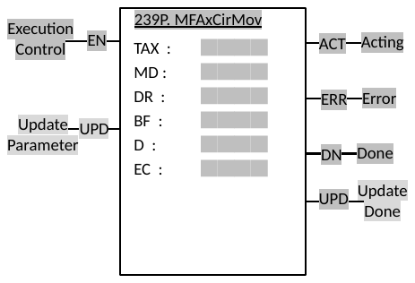
Operands TAX : Total Axis Number MD : Operation Mode DR : Direction BF : Continuous Mode D : Parameter Register Start Address EC : Register for Error code |
|||||||||||||||||||||||||||||||||||||||||||||||||||||||||||||||||||||||||||||||||||||||||||||||||||||||||||||||||||||||||||
|
Relay and Register
|
||||||||||||||||||||||||||||||||||||||||||||||||||||||||||||||||||||||||||||||||||||||||||||||||||||||||||||||||||||||||||||
|
Function Description |
||||||||||||||||||||||||||||||||||||||||||||||||||||||||||||||||||||||||||||||||||||||||||||||||||||||||||||||||||||||||||||
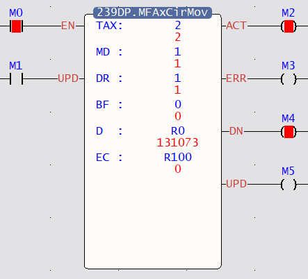
TAX (Total Axis Number) : Axes number in movement – 2 ~ 3 MD (Operation Mode) : 0 – Absolute Positioning, 1 – Relative Positioning. DR (Direction) : 1 – Positive, 2 – Negative. BF (Continuous Mode) : 0: Stop Current Movement 1: Wait Current Mov Finish 2: Continue with Lower Speed 3: Continue with Current Speed 4: Continue with New Speed 5: Continue with higher Speed D : First Register Address of Data. EC : Register for Error Code.
When execution control (EN) is triggered in lower edge, the Fun239 will be stopped, and all the coils will be reset.
Motion data in parameter D:
|
||||||||||||||||||||||||||||||||||||||||||||||||||||||||||||||||||||||||||||||||||||||||||||||||||||||||||||||||||||||||||||
|
Program Example |
||||||||||||||||||||||||||||||||||||||||||||||||||||||||||||||||||||||||||||||||||||||||||||||||||||||||||||||||||||||||||||
|
Ladder
|
||||||||||||||||||||||||||||||||||||||||||||||||||||||||||||||||||||||||||||||||||||||||||||||||||||||||||||||||||||||||||||
|
||||||||||||||||||||||||||||||||||||||||||||||||||||||||||||||||||||||||||||||||||||||||||||||||||||||||||||||||||||||||||||
|
||||||||||||||||||||||||||||||||||||||||||||||||||||||||||||||||||||||||||||||||||||||||||||||||||||||||||||||||||||||||||||
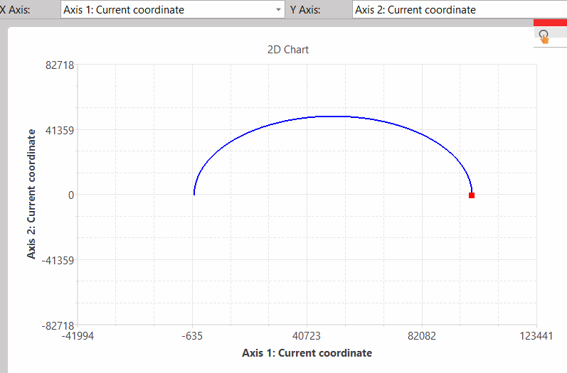
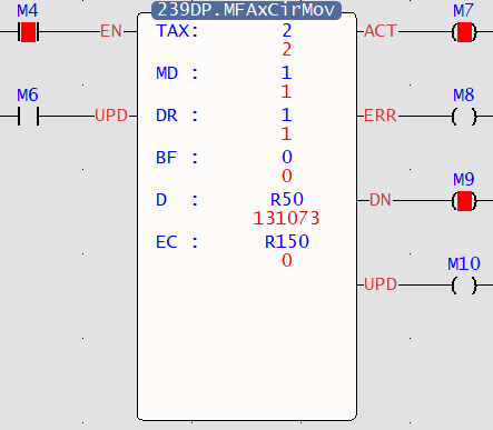 Combining the use of Fun238 and Fun239
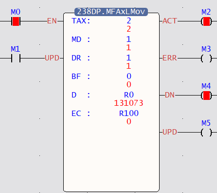
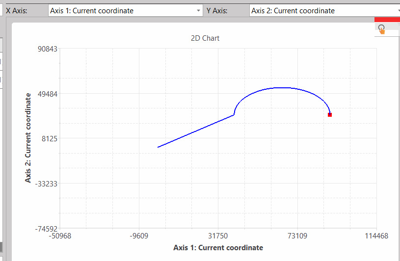
6-5-7 Fun240 Path Movement (MFPathMov)
|
Fun240 D P MFPathMov |
Path Movement |
Fun240 D P MFPathMov |
||||||||||||||||||||||||||||||||||||||||||||||||||||||||||||||||||||||||||||||||||||||||||||||||||||||||||||||||||||||||||||||||||||||||||||||||||||||||||||||||||||||||||||||||||||||
|
Command Description |
||||||||||||||||||||||||||||||||||||||||||||||||||||||||||||||||||||||||||||||||||||||||||||||||||||||||||||||||||||||||||||||||||||||||||||||||||||||||||||||||||||||||||||||||||||||||
|
Ladder Symbol
|
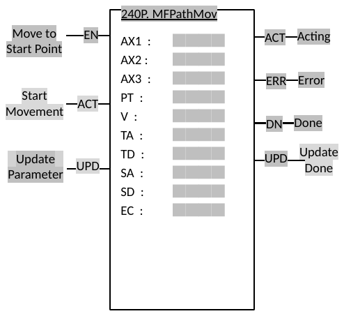
Operands AX1 : Axis 1 Number AX2 : Axis 2 Number AX3 : Axis 3 Number PT : Path Number V : Velocity TA : Acceleration Time TD : Deceleration Time SA : Acceleration S Curve Percentage SD : Deceleration S Curve Percentage EC : Register for Error Code |
|||||||||||||||||||||||||||||||||||||||||||||||||||||||||||||||||||||||||||||||||||||||||||||||||||||||||||||||||||||||||||||||||||||||||||||||||||||||||||||||||||||||||||||||||||||||
|
Relay and Register
|
||||||||||||||||||||||||||||||||||||||||||||||||||||||||||||||||||||||||||||||||||||||||||||||||||||||||||||||||||||||||||||||||||||||||||||||||||||||||||||||||||||||||||||||||||||||||
|
Function Description |
||||||||||||||||||||||||||||||||||||||||||||||||||||||||||||||||||||||||||||||||||||||||||||||||||||||||||||||||||||||||||||||||||||||||||||||||||||||||||||||||||||||||||||||||||||||||
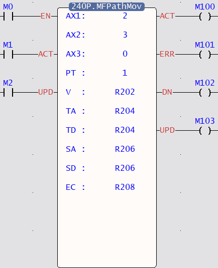
AX1 : EtherCAT axis number range 1~16 AX2 : EtherCAT axis number range 1~16 AX3 : EtherCAT axis number range 1~16r PT : Path Number range 1~10 V : Velocity is positive integer and include the decimal point in the axis table of the main axis (AX1). TA : Acceleration time of the interpolation. The unit is milli-second. TD : Deceleration time of the interpolation. The unit is milli-second. SA : The percentage of the S curve in acceleration. The range is 0~1000‰. SD : The percentage of the S curve in acceleration. The range is 0~1000‰. EC : Register for Error Code.
When execution control (EN) is triggered in lower edge, the Fun240 will be stopped, and all the coils will be reset.
When start movement (ACT) is triggered in lower edge, the Fun240 will be halt. And the function will be resumed when ACT is back to high level.
|
||||||||||||||||||||||||||||||||||||||||||||||||||||||||||||||||||||||||||||||||||||||||||||||||||||||||||||||||||||||||||||||||||||||||||||||||||||||||||||||||||||||||||||||||||||||||
|
Program Example |
||||||||||||||||||||||||||||||||||||||||||||||||||||||||||||||||||||||||||||||||||||||||||||||||||||||||||||||||||||||||||||||||||||||||||||||||||||||||||||||||||||||||||||||||||||||||
|
Ladder
|
||||||||||||||||||||||||||||||||||||||||||||||||||||||||||||||||||||||||||||||||||||||||||||||||||||||||||||||||||||||||||||||||||||||||||||||||||||||||||||||||||||||||||||||||||||||||
|
||||||||||||||||||||||||||||||||||||||||||||||||||||||||||||||||||||||||||||||||||||||||||||||||||||||||||||||||||||||||||||||||||||||||||||||||||||||||||||||||||||||||||||||||||||||||
Tip: press ← → to switch chapters, Ctrl+K to search