Speed Control and Torque Control
This section describes the speed control and the torque control required for the M-PLC. You cannot retrieve the speed control and the torque control from the PLC. To use the speed and torque control functions, please retrieve through the Motion Flow function. The speed control is the function required for setting the speed/torque control mode to enable status.
15-1 Speed Control
In the speed control mode, it is mainly to control the rotation speed of the motor, and the maximum torque limit protection can be set in the speed control mode. To execute the speed control of the specified axis, it can be called by the motion flow speed control module or the ladder diagram instruction. The following will explain how to use it individually:
-
- Motion Flow – Speed Control Module
Before using the flow block, the user must first set the motion link setting and motion axis setting.
Then add a new motion flow by clicking [Motion Flow] in [Project Management], and drag the speed control from the toolbox to the motion flow, as shown in the figure below. If no other motion flow is required, add an end flow block at the end.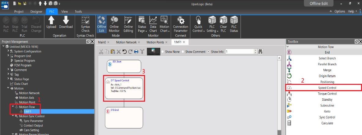
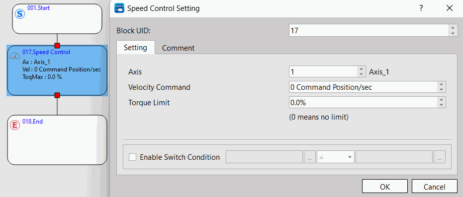
Double-click the speed control in the motion flow to set the axis to be controlled, speed command and torque limit.
|
Introduction of Flow Block Function |
|
|
Function |
Description |
|
Flow Block No. |
The system will assign it automatically, and the user can change it by himself (but the flow block number cannot be repeated). |
|
Axis |
Axis to execute speed control |
|
Speed Command |
Speed to execute speed control, the speed command can be entered with a minus sign, which means reverse rotation. (unit is command position/second). |
|
Torque Limit |
If the torque limit is set to 100, the servo torque limit will be 10%, if it is set to 0, it will not be limited. (in units of 0.1%) |
|
Switch Condition |
Set the conditions for switching to the next flow block. If the user does not enable switch conditions,then jump directly to the next flow block with the current motor state. |
|
Comment |
The user can input the function of this flow block or application comments, etc. |
-
- Speed Control Ladder
Before using FUN194 speed control, the user must first set the motion link setting and motion axis setting.
- Speed Control Ladder
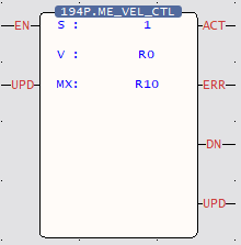
The following is the description of the speed control function. The user can use it after setting it on the ladder diagram, and there is no need to set the motion flow block.
|
Fun194. MFVelCtl |
Parameter Description |
|
|
V : Velocity |
Simple Speed Control Example
1. After completing the setting of the above motion flow block, trigger the function of servo initialization (FUN187) in the ladder diagram, and set the enable (SERVO ON) ladder diagram logic (M10600).
Note: If you need a detailed description of the special register, please refer to the instruction manual – special register chapter.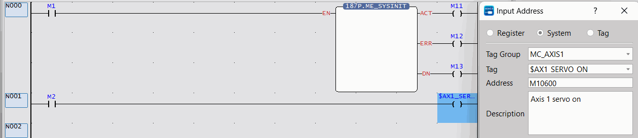
The following will introduce the control methods of the ladder diagram and the motion flow chart respectively.
2. Control through the flow chart. If the user wants to use the ladder diagram control, please skip to step 3.
Then use FUN176 to control the programmed motion flow, and then you can perform the speed control function of the flow block.
Note: The ID of FUN176 must be the same as the number of the motion flow to be controlled.
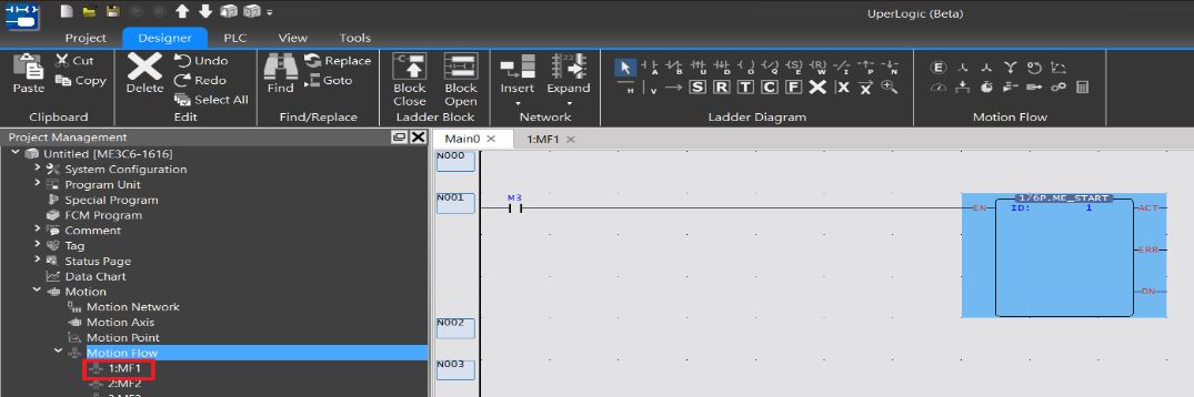
Users can also refer to the settings below for a simple test.
Note: The following parameters are based on SC3 as an example. Since the servo parameters may be changed, it is recommended that the user perform a test run to ensure safety before use.
|
Motion Axis Setting |
Flow Block Setting |
|
|
|
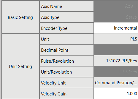
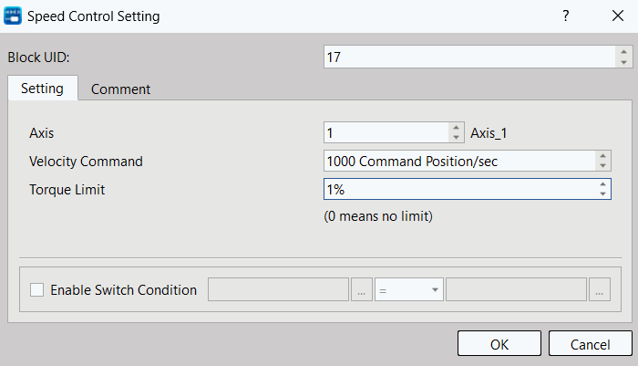
3. Control through the ladder diagram. If the user wants to use the flow block control, he needs to go to step 2 and then directly jump to step 4.
Drag FUN194 to the ladder diagram, and set R0 to 1000 and R10 to 1 to download and execute the project.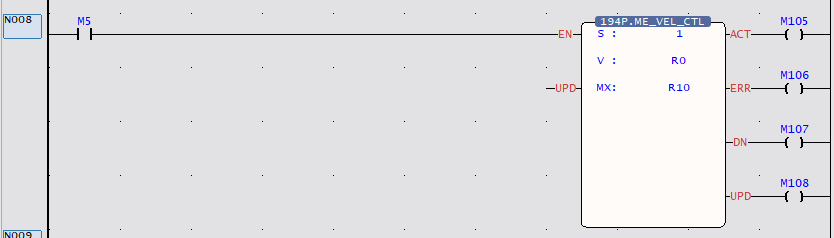
4. Regardless of whether you use the ladder diagram or the motion flow, you can check the status of the axis through the motion monitoring table after execution.
The motion monitoring table is in the upper PLC > Motion Graph > Motion Monitoring Table.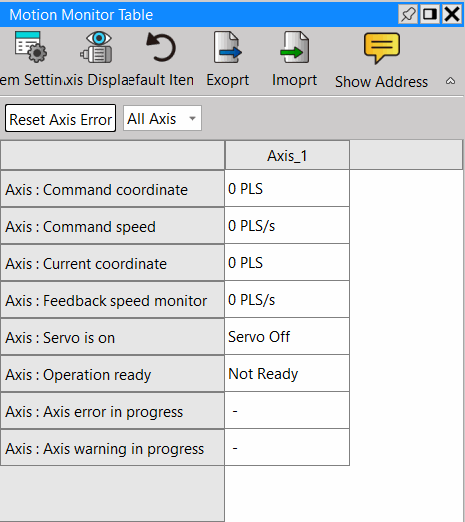
15-2 Torque Control
In the torque control mode, it mainly controls the rotation torque of the motor, and the maximum speed limit protection can be set in the torque control mode. To execute the speed control of the specified axis, it is called by the motion flow speed control module. As explained below:
Note: When the motor implements torque control, if the torque does not reach the set value, the speed will continue to rise. Therefore, please add the speed limit appropriately when using it to ensure the safety of operation.
-
- Motion Flow – Torque Control Module
Before using the flow block, the user must first set the motion link setting and motion axis setting.
Then add a new motion flow by clicking [Motion Flow] in [Project Management], and then drag the speed control from the toolbox to the motion flow, as shown in the figure below. If no other motion flow is required, add an end process flow at the end.
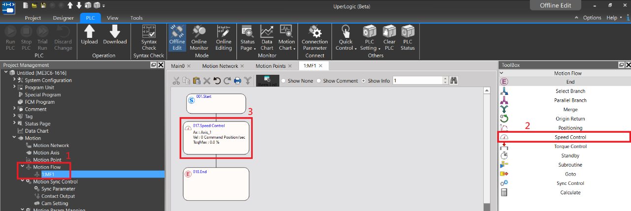
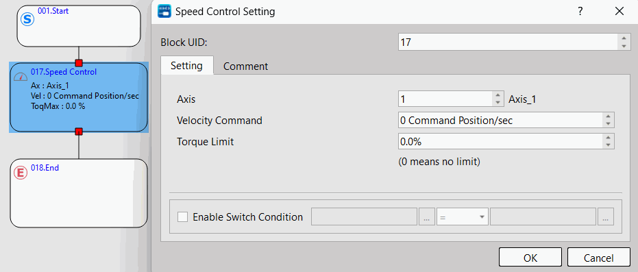
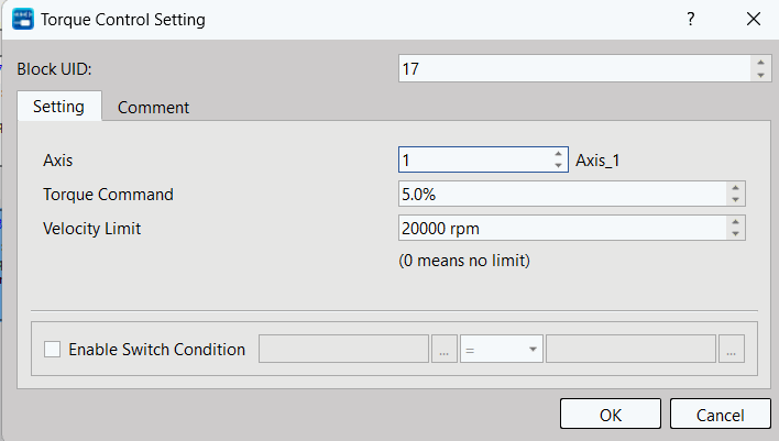
Double-click the torque control in the motion flow to set the axis to be controlled, speed command and torque limit.
|
Introduction of Flow Block Function |
|
|
Function |
Description |
|
Flow Block No. |
The system will assign it automatically, and the user can change it by himself (but the flow block number cannot be repeated). |
|
Axis |
Axis to execute speed control |
|
Torque Command |
Torque to execute torque control, the torque command can be entered with a minus sign, which means the direction. (in units of 0.1%). |
|
Speed Limit |
Maximum speed limit, if it is set to 0, it will not be limited. (unit is command position/second). |
|
Switch Condition |
Set the conditions for switching to the next flow block. If the user does not enable switch conditions,then jump directly to the next flow block with the current motor state. |
|
Comment |
The user can input the function of this flow block or application comments, etc. |
-
- Ladder Diagram Speed Control
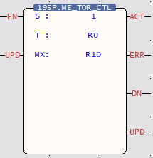
Before using the FUN195 torque control, the user must first set the motion link setting and motion axis setting.
- Ladder Diagram Speed Control
The following is the description of the torque control function. The user can use it after setting it on the ladder diagram, and there is no need to set the motion flow block.
|
Fun194. MFVelCtl |
Parameter Description |
|
|
|
Simple Torque Control Example
1. After completing the setting of the above motion flow block, trigger the function of servo initialization (FUN187) in the ladder diagram, and set the enable (SERVO ON) command (M10600).
Note: If the user wants to know more about this part, please refer to the corresponding chapter.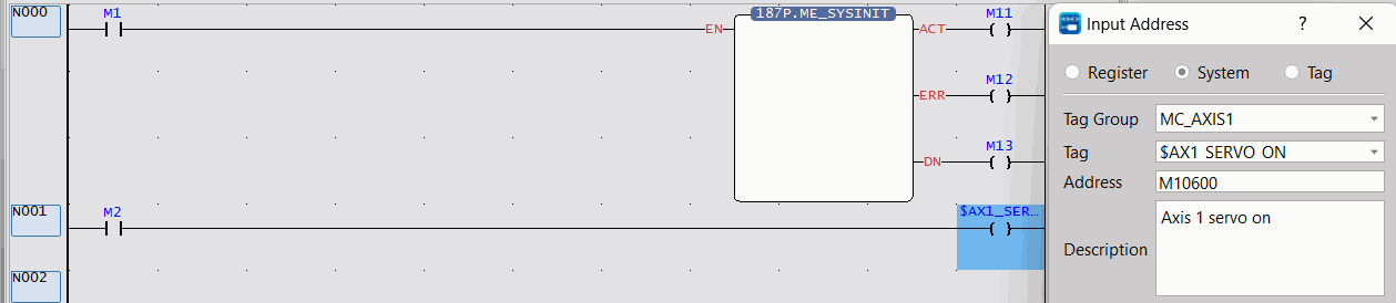
The following will introduce the control methods of the ladder diagram and the motion flow chart respectively.
2. Control through the flow chart. If the user wants to use the ladder diagram control, please skip to step 3.
Then use FUN176 to control the programmed motion flow, and then you can perform the torque control function of the flow block.
Note: The ID of FUN176 must be the same as the number of the motion flow to be controlled.
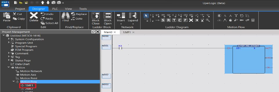
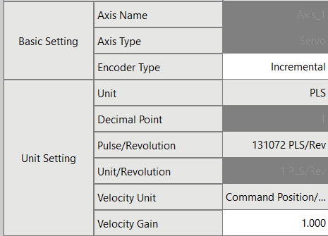
Users can also refer to the settings below for a simple test.
Note: The following parameters are based on SC3 as an example. Since the servo parameters may be changed, it is recommended that the user perform a test run to ensure safety before use.
|
Motion Axis Setting |
Flow Block Setting |
|
|
|
3. Control through the ladder diagram. If the user wants to use the process block control, he needs to go to step 2 and then directly jump to step 4.
Drag FUN195 to the ladder diagram, and set R0 to 5, R10 to 20000 to download and execute the project.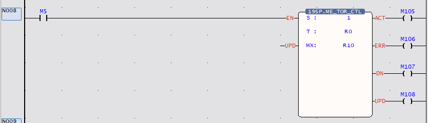
4. Regardless of whether you use the ladder diagram or the motion flow, you can check the status of the axis through the motion monitoring table after execution.
The motion monitoring table is in the upper PLC > Motion Graph > Motion Monitoring Table.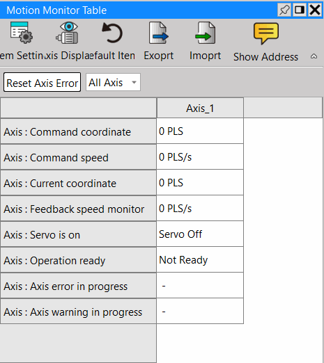
Tip: press ← → to switch chapters, Ctrl+K to search