5.1 Manipulating Parameters(Pn▯▯▯)
This section describes the classifications, notation, and setting methods for the parameters given in this manual.
5.1.1 Parameter Classification
There are the following two types of servo driver parameters.
|
Classification |
Meaning |
|
Setup Parameters |
Parameters for the basic settings that are required for operation. |
|
Tuning Parameters |
Parameters that are used to adjust servo performance. |
NOTE: When you edit parameters with a Panel Operator or Digital Operator, only setup parameters are displayed by default. To edit tuning parameters, set Pn00B to n.▯▯▯1 (Display all parameters).
|
Parameter |
Meaning |
When |
Classification |
|
|
Pn00B |
n.▯▯▯0 [default |
Display only setup parameters. |
After restart |
Setup |
|
n.▯▯▯1 |
Display all parameters. |
|||
5.1.2 Notation for Parameters
There are two types of notations used for parameters that depend on whether the parameter requires a numeric setting (parameter for numeric setting) or requires the selection of a function (parameter for selecting a function).
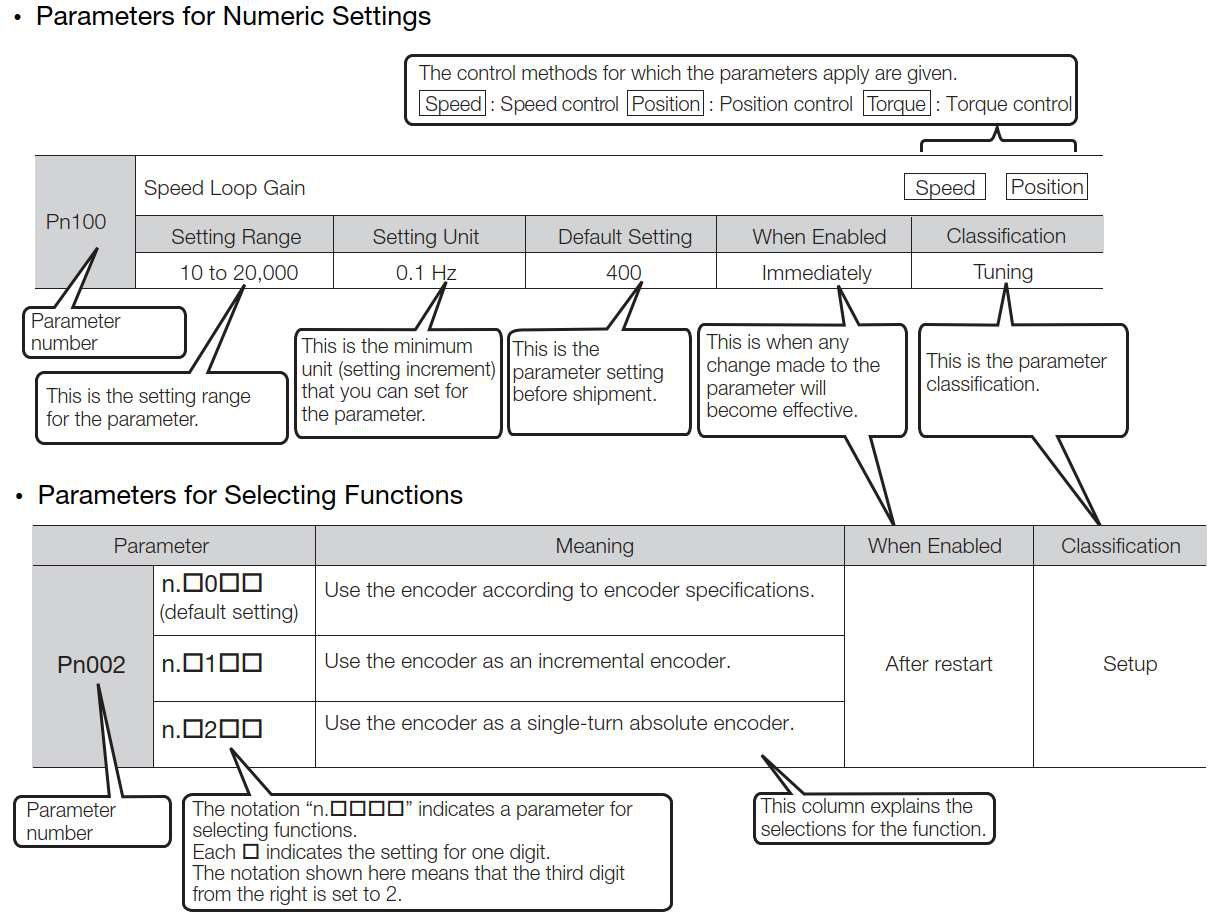
5.1.3 Parameter Setting Methods
You can use the Protuner or the Panel Operator to set parameters.
5.1.4 Write Protection Setting for Parameters
You can prohibit writing parameters from the Panel Operator or the Digital Operator. Even if you do, you will still be able to change parameter settings from the Protuner.
5.1.5 Initializing Parameter Settings
You can return the parameters to their default settings.
This function will not initialize the settings of the parameters that are adjusted for the FA00C, FA00D, FA00E, and FA00F utility functions.
|

Preparations
Always check the following before you initialize the parameter settings. • The parameters must not be write prohibited.
• The servo must be OFF.
Applicable Tools
The following table lists the tools that you can use to initialize the parameter settings.
|
Too |
FA No./Function Name |
Reference |
|
Panel Operator |
FA005 |
ParameterSetup Initialize Parameters(FA005) |
|
ProTuner |
[Edit Parameters ] - [Parameter Restore factory values] |
5.2 The EtherCAT of Communication Specification
The EtherCAT communication setting setup by Servo Parameter Pn013.
5.2.1 The Setting of EtherCAT Station Address
|
Pn013 |
|
|||||||
|
Setup Range |
Setup Unit |
default setting |
When Enabled |
Classification |
||||
|
0000〜FFFF |
— |
1 |
After restart |
Setup |
||||
5.3 Power Supply Type Settings for the Main Circuit and Control Circuit
A servo driver with a 220-VAC power supply input can be operated on either an AC power supply input or DC power supply input to the main and control circuits. If you select an AC power supply input, you can operate the servo driver on either a single-phase power supply input or a three-phase power supply input. This section describes the settings related to the power supplies.
5.3.1 AC Power Supply Input/DC Power Supply Input Setting
Set Pn001 = n.▯X ▯▯ (Main Circuit Power Supply AC/DC Input Selection) to specify whether to use an AC or DC power supply input for the main circuit power supply to the servo driver.
If the setting of Pn001 = n.▯X ▯▯ does not agree with the actual power supply input, an A.330 alarm (Main Circuit Power Supply Wiring Error) will occur.
Example: Examples of When an A.330 Alarm (Main Circuit Power Supply Wiring Error) Occurs
● A DC power supply is connected between the B1/ and 2 terminals, but an AC power supply input is specified (Pn001 = n.▯0 ▯▯).
● An AC power supply is input to the L1, L2, and L3 terminals, but a DC power supply is specified (Pn001 = n.▯1 ▯▯).
|
Parameter |
Meaning |
When Enabled |
Classification |
|
|
Pn001 |
n.▯0▯▯ |
Use an AC power supply input. |
After restart |
Setup |
|
n.▯1▯▯ |
Use a DC power supply input. |
|||
|
|
|
●Connect the AC or DC power supplies to the specified servo driver terminals. • Connect an AC power supply to the L1, L2, and L3 terminals and the L1C and L2C terminals on the servo driver. • Connect a DC power supply to the B1/ and 2 terminals and the L1C and L2C terminals on the servo driver. There is a risk of failure or fire. ●Always specify a DC power supply input (Pn001 = n.▯1 ▯▯) before you input DC power for the main circuit power supply. If you input DC power without specifying a DC power supply input (i.e., without setting Pn001 to n.▯1 ▯▯), the servo driver’s internal elements may burn and may cause fire or damage to the equipment. ●With a DC power supply input, time is required to discharge electricity after the main power supply is turned OFF. A high residual voltage may remain in the servo driver after the power supply is turned OFF. Be careful not to get an electric shock. ●Install fuses on the power supply line if you use DC power. ●The Servomotor returns regenerative energy to the power supply. If you use a servo driver with a DC power supply input, regenerative energy is not processed. Process the regenera-tive energy at the power supply. |
 WARNING
5.3.2 Single-phase AC Power Supply Input/Three-phase AC Power Supply Input Setting
If you use a single-phase, 220-VAC power supply input for the servo driver’s main circuit power supply, set parameter Pn00B to n.▯1 ▯▯ (Use a three-phase power supply input as a single-phase power supply input).
This restriction does not affect the SC3 03A model.
|
Parameter |
Meaning |
When Enabled |
Classification |
|
|
Pn00B |
n.▯0▯▯ |
Use a three-phase power supply input. |
After restart |
Setup |
|
n.▯1▯▯ |
Use a three-phase power supply input as a single-phase power supply input. |
|||
|
|
1. If you use a single-phase power supply input without specifying a single-phase AC power supply (Pn00B = n.▯1▯▯), an A.F10 alarm (Power Supply Line Open Phase) will occur. 2. Not all Servo driver can be run on a single-phase AC power supply input. If you connect a single-phase AC |

power supply input to a servo driver that does not support single-phase power, an A.F10 alarm (Power Supply Line Open Phase) will occur.
3. If you use a single-phase 220AC power supply input, the torque-motor speed characteristic of the Servomotor will not be the same as for a three-phase AC power supply input. Decide whether to use a single-phase or three-phase AC power supply input after checking the characteristics given in the Servomotor manual or catalog.
5.4 Functions and Settings for the /S-ON (Servo ON) Signal
The /S-ON (Servo ON) signal is used to enable Servomotor operation. This section describes the function of and settings for the /S-ON signal.
5.4.1 Function of the /S-ON (Servo ON) Signal
|
Type |
Signal |
Connector Pin No. |
Signal Status |
Function |
|
Input |
/S-ON |
Must be allocated |
ON (closed) |
Power is supplied to the Servomotor to enable operation. |
|
OFF (open) |
Power supply to the Servomotor is stopped and operation is disabled. |
You can use Pn50A = n.▯▯X ▯ (/S-ON (Servo ON) Signal Allocation) to allocate the /S-ON signal to a different input signal terminal.
2. Input the /S-ON signal while the Servomotor is stopped. You cannot turn ON the servo while the Servomotor is operating. |

5.4.2 Setting to Keep the Servo ON and Supply Power to the Motor Continuously (For Pulses Type)
You can set Pn50A = n.▯▯X ▯ (/S-ON (Servo ON) Signal Allocation) to 9 (The signal is always active) to keep the servo ON and supply power to the motor continuously.
|
Parameter |
Meaning |
When Enabled |
Classification |
|
|
Pn50A |
n.▯▯0▯ |
he S-ON signal is active when CN1-40 input signal is ON (closed). |
After restart |
Setup |
|
n.▯▯9▯ |
The signal is always active. (The /S-ON signal is always active.) |
|||
2. If a resettable alarm occurs and operation is disabled (power is not supplied to the motor), operation will be automatically enabled (power will be supplied to the motor) when the alarm is reset. If you set this parameter to keep the servo ON continuously, the Servomotor or machine may perform unexpected operation when an alarm is reset. |

5.5 Motor Direction Setting
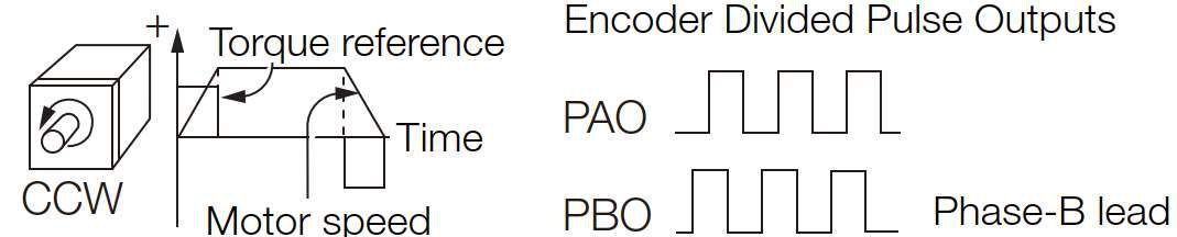
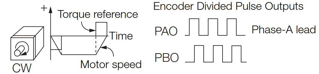
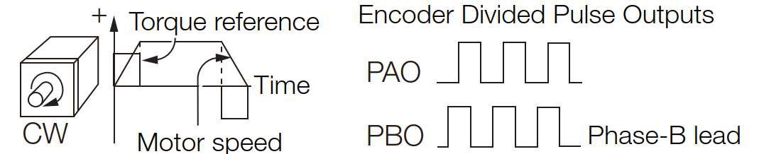
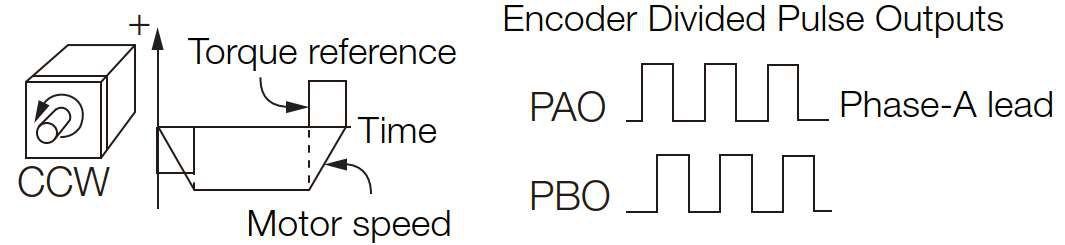
You can reverse the direction of Servomotor rotation by changing the setting of Pn000 = n.▯▯▯X (Rotation Direction Selection) without changing the polarity of the speed or position reference.
This causes the rotation direction of the Servomotor to change, but the polarity of the signals, such as encoder output pulses, output from the servo driver do not change. Set the appropriate direction for your system. The default setting for forward rotation is counterclockwise (CCW) as viewed from the load end of the Servomotor.
|
Parameter |
Forward/Reve rse |
Motor Direction and Encoder Divided Pulse Outputs |
Applicable Overtravel Signal (OT) |
|
|
Pn00 0 |
n.▯▯▯0 (Default |
Forward |
|
P-OT (For- ward Drive Prohibit) |
|
Reverse |
|
N-OT |
||
|
n.▯▯▯1 (Reverse Rota-tion Mode) |
Forward |
|
P-OT (For- ward Drive Prohibit) |
|
|
反Reverse reference |
|
N-OT |
||
5.6 Overtravel and Related Settings
Overtravel is a function of the servo driver that forces the Servomotor to stop in response to a signal input from a limit switch that is activated when a moving part of the machine exceeds the safe range of movement.
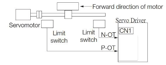
The overtravel signals include the P-OT (Forward Drive Prohibit) and the N-OT (Reverse Drive Prohibit) signals.
You use the P-OT and N-OT signals to stop the machine by installing limit switches at the positions where you want to stop the machine that is operated by the Servomotor. A servo driver wiring example is provided below.
Using the overtravel function is not necessary for rotating applications such as rotary tables and conveyors. No wiring for
overtravel input signals is required. This section describes the parameters settings related to overtravel.
|
|
|
● To prevent accidents that may result from contact faults or disconnections, use normally closed limit switches. Do not change the default settings of the polarity of the overtravel signals (P-OT and N-OT). ● If you use a Servomotor for a vertical axis, the /BK (Brake) signal will remain ON (i.e., the brake will be released) when overtravel occurs. This may result in the workpiece falling when overtravel occurs. To prevent the workpiece from falling, set Pn001 to n.▯▯1 ▯ to place the Servomotor in a zero-clamped state when it stops. ● A base block state is entered after stopping for overtravel. This may cause the Servomotor to be pushed back by an external force on the load shaft. To prevent the Servomotor from being pushed back, set Pn001 to n.▯▯1 ▯ to place the Servomotor in a zero-clamped state when it stops. |
 CAUTION
5.6.1 Overtravel Signals
The overtravel signals include the P-OT (Forward Drive Prohibit) and the N-OT (Reverse Drive Prohibit) signals.
|
Type |
Signal |
Connector Pin No. |
Signal |
Meaning |
|
Input |
P-OT |
CN1-IN2 |
ON |
Forward drive is enabled (actual operation). |
|
OFF |
Forward drive is prohibited |
|||
|
N-0T |
CN1-IN3 |
ON |
Reverse drive is enabled (actual operation). |
|
|
OFF |
Reverse drive is prohibited |
You can operate the Servomotor in the opposite direction during overtravel by inputting a reference.。
5.6.2 Setting to Enable/Disable Overtravel
You can use Pn50A = n.X ▯▯▯ (P-OT (Forward Drive Prohibit) Signal Allocation) and Pn50B = n.▯▯▯X (N-OT (Reverse Drive Prohibit) Signal Allocation) to enable and disable the overtravel function.
You do not need to wire the overtravel input signals if you are not going to use the overtravel function.
|
Parameter |
Meaning |
When Enabled |
Classification |
|
|
Pn50A |
n. 2▯▯▯ |
The forward overtravel function is enabled and the P-OT (Forward Drive Prohibit) signal is input from CN1-CN0. (CN1-IN1 For Pulses Type ) |
After restart |
Setup |
|
n. 8▯▯▯ |
The forward overtravel function is disabled. Forward drive is always enabled. |
|||
|
Pn50B |
n.▯▯▯3 |
The reverse overtravel function is enabled |
After restart |
Setup |
|
n.▯▯▯8 |
The reverse overtravel function is disabled. Reverse drive is always enabled. |
|||
5.6.3 Motor Stopping Method for Overtravel
You can set the stopping method of the Servomotor when overtravel occurs in Pn001 = n.▯▯XX (Motor Stopping Method for Servo OFF and Group 1 Alarms and Overtravel Stopping Method).
|
Parameter |
Motor Stopping Method* |
Status after Stopping |
When Enabled |
Classification |
|
|
Pn001 |
n.▯▯00 [default |
Dynamic brake |
Coasting |
After restart |
Setup |
|
n.▯▯01 |
|||||
|
n.▯▯02 |
Coasting |
||||
|
n.▯▯1▯ |
Deceleration according to setting of Pn406 |
Zero clamp |
|||
|
n.▯▯2▯ |
Coasting |
||||
|
n.▯▯3▯ |
Deceleration according to setting of Pn30A |
Zero clamp |
|||
|
n.▯▯4▯ |
Coasting |
||||
* You cannot decelerate a Servomotor to a stop during torque control. For torque control, the Servomotor will be stopped with the dynamic braking or coast to a stop (according to the setting of Pn001 = n.▯▯▯X (Motor Stopping Method for Servo OFF and Group 1 Alarms)), and then the Servomotor will enter a coasting state.
Stopping the Servomotor by Setting Emergency Stop Torque
To stop the Servomotor by setting emergency stop torque, set Pn406 (Emergency Stop Torque).If Pn001 = n.▯▯X ▯ is set to 1 or 2, the Servomotor will be decelerated to a stop using the torque set in Pn406 as the maximum torque. The default setting is 800%. This setting is large enough to allow you to operate the Servomotor at the maximum torque. However, the maximum emergency stop torque that you can actually use is the maximum torque of the Servomotor.
|
Pn406 |
|
Torque |
|||||||
|
Setting Range |
Setting Unit |
Default Setting |
When Enabled |
Classification |
|||||
|
0〜800 |
1% * |
800 |
Immediately |
Setup |
|||||
* Set a percentage of the motor rated torque.
Stopping the Servomotor by Setting the Deceleration Time
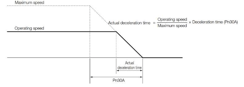
To specify the Servomotor deceleration time and use it to stop the Servomotor, set Pn30A (Deceleration Time for Servo OFF and Forced Stops).
|
Pn30A |
|
|||||||
|
Setting Range |
Setting Unit |
Default Setting |
When Enabled |
Classification |
||||
|
0〜10000 |
1ms |
0 |
Immediately |
Setup |
||||
If you set Pn30A to 0, the Servomotor will be stopped with a zero speed.
The deceleration time that you set in Pn30A is the time to decelerate the Servomotor from the maximum motor speed.
5.6.4 Overtravel Warnings
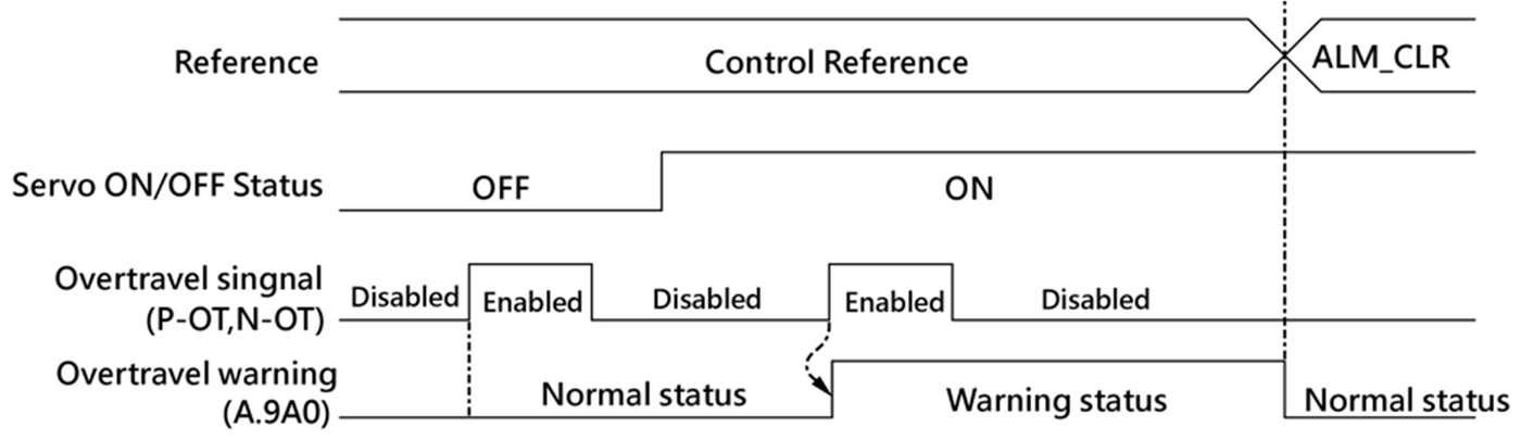
You can set the system to detect an A.9A0 warning (Overtravel) if overtravel occurs while the servo is ON. This allows the servo driver to notify the host controller with a warning even when the overtravel signal is input only momentarily. An alarm occurs only if overtravel occurs while the servo is ON. An overtravel warning will not be detected when the servo is OFF, even if overtravel occurs.
|
• The occurrence of an A.9A0 warning will not stop the motor or have any affect on host controller motion
controller, operation may be affected when an overtravel warning occurs (e.g., motion may stop or not stop). Confirm the specifications and programming in the host controller. • When overtravel occurs, the servo driver will perform stop processing for overtravel. Therefore, when an A.9A0 warning occurs, the Servomotor may not reach the target position specified by the host controller. Check the feedback position to make sure that the axis is stopped at a safe position. |

The following parameter is set for this function.
|
Parameter |
Meaning |
When |
Classificati on |
|
|
Pn00D |
n.0▯▯▯ |
Do not detect overtravel warnings. |
restart |
Setup |
|
n.1▯▯▯ |
Detect overtravel warnings. |
|||
A timing chart for warning detection is provided below.
NOTE:
1. Warnings are detected for overtravel in the same direction as the reference.
2. Warnings are not detected for overtravel in the opposite direction from the reference. Example: A warning will not be output for a forward reference even if the N-OT signal turns ON.
3. A warning status can be detected in either the forward or reverse direction if there is no reference.
4. A warning status will not be detected when the servo is turned ON even if overtravel status exists.
5. A warning status is not related to Servo ON/Servo OFF or the overtravel signal status. It will be cleared by ALM_CLR. 6. When an overtravel warning status is triggered, it will not be triggered again until the it is cleared.
7. When the software limit is detected, An overtravel warning status will still be triggered.
5.7 Holding Brake
A holding brake is used to hold the position of the moving part of the machine when the servo driver is turned OFF
so that moving part does not move due to gravity or an external force. You can use the brake that is built into a
Servomotor with a Brake, or you can provide one on the machine.
The holding brake is used in the following cases.
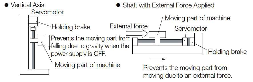
|

5.7.1 Brake Operating Sequence
You must consider the brake release delay time and the brake operation delay time to determine the brake operation timing, as described below.
|

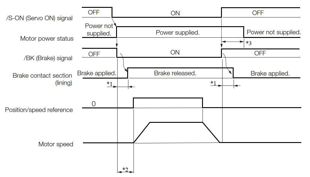
*1. Rotary Servomotors: The brake delay times for Servomotors with Holding Brakes are given in the following
table. The operation delay times in the following table are examples for when the power supply is switched on the DC side. You must evaluate the actual brake delay times on the actual equipment before using the application.
*2. Before you output a reference from the host controller to the Servo Driver, wait for at least 50 ms plus the brake release delay time after you turn ON the /S-ON signal.
*3. Use the following parameters to set the timing of when the brake will operate and when the servo will be turned OFF. • Rotary Servomotors: Pn506 (Brake Reference-Servo OFF Delay Time), Pn507 (Brake Reference Output Speed Level), and Pn508 (Servo OFF-Brake Command Waiting Time)
• Linear Servomotors: Pn506 (Brake Reference-Servo OFF Delay Time), Pn508 (Servo OFF-Brake Command Waiting Time), and Pn583 (Brake Reference Output Speed Level)
*4. After the SV_ON command is sent, wait for the brake release time plus an additional 50ms then output the command that sent by the upper device to the servo driver.
*5. Please use the following parameters to set up the brake action and servo OFF time: Pn506(Brake command – Servo OFF delay time),
Pn507(Brake command output speed value),
Pn508(Servo OFF – Brake command wait time)
5.7.2 /BK (Brake) Signal
The following settings are for the output signal that controls the brake. The /BK (Brake) signal is not allocated by default. To use the brake, change the setting of Pn50F = n.▯X ▯▯ (/BK (Brake Output) Signal Allocation). The /BK signal is turned OFF (to operate the brake) when the servo is turned OFF or when an alarm is detected. You can adjust the timing of brake operation (i.e., the timing of turning OFF the /BK signal) with the servo OFF delay time (Pn506).
|
Type |
Singal |
Connecter Pin No. |
Singal Status |
Meaning |
|
Output |
/BK |
Must be allocated |
ON(Closed) |
Relesases the brake |
|
OFF(Open) |
Activates the brake |
NOTE: The /BK signal will remain ON during overtravel. The brake will not be applied.
Allocating the /BK (Brake) Signal
To use the brake, you must allocate an output signal for the /BK signal.
Set the allocation for the /BK signal in Pn50F = n.▯X ▯▯ (/BK (Brake Output) Signal Allocation).
|
Parameter |
Connecter Pin No. |
meaning |
When |
Classificati on |
|
|
Pn50F |
n.▯0▯▯ |
CN1-7,8 |
The /BK Signal is output from CN1-OUT0 |
After |
setup |
|
n.▯1▯▯ |
CN1-9,10 |
The /BK Signal is output from CN1-OUT1 |
|||
|
n.▯2▯▯[default |
CN1-11,12 |
The /BK Signal is output from CN1-OUT2 |
|||
|
n.▯3▯▯ |
CN1-32,33 |
The /BK Signal is output from CN1-OUT3 |
|||
|
n.▯4▯▯ |
CN1-34,35 |
The /BK Signal is output from CN1-OUT4 |
|||
|
n.▯5▯▯ |
CN1-36,37 |
The /BK Signal is output from CN1-OUT5 |
|||
|
n.▯6▯▯ |
— |
The /BK Signal is not used |
connector pin. If you did so, the /TGON signal would be turned ON by the falling speed on a vertical axis, and the brake would not operate. |

5.7.3 Output Timing of /BK (Brake) Signal When the Servomotor Is Stopped
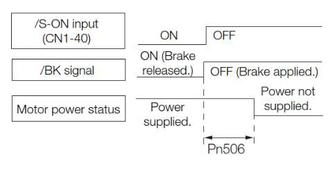
When the Servomotor is stopped, the /BK signal turns OFF at the same time as the /S-ON signal turns OFF. Use the servo OFF delay time (Pn506) to change the timing to turn OFF power supply to the motor after the /S-ON signal turns OFF.
|
Pn506 |
|
|||||||
|
Setting Range |
Setting Unit |
Default Setting |
When Enabled |
Classification |
||||
|
0〜50 |
1ms |
0 |
Immediately |
Setup |
||||
• When the Servomotor is used to control a vertical axis, the machine moving part may move slightly due to gravity or an external force. You can eliminate this slight motion by setting the servo OFF delay time (Pn506) so that power supply to the motor is stopped after the brake is applied.
• This parameter sets the timing of stopping power supply to the Servomotor while the Servomotor is stopped.
|

5.7.4 Output Timing of /BK (Brake) Signal When the Servomotor Is Operating
If an alarm occurs while the Servomotor is operating, the Servomotor will start stopping and the /BK signal will be turned OFF. You can adjust the timing of /BK signal output by setting the brake reference output speed level (Rotary Servomotors: Pn507, Linear Servomotors: Pn583) and the Servo OFF-Brake Command Waiting Time (Pn508). NOTE: If zero-speed stopping is set as the stopping method for alarms, the setting of Pn506 (Brake Reference Servo OFF
Delay Time) is used after the motor stops.
|
Pn507 |
|
|||||||
|
Setting Range |
Setting Unit |
Default Setting |
When Enabled |
Classification |
||||
|
0〜10000 |
1min-1 (RPM) |
100 |
Immediately |
Setup |
||||
|
Pn508 |
|
|||||||
|
Setting Range |
Setting Unit |
Default Setting |
When Enabled |
Classification |
||||
|
10〜100 |
10ms |
50 |
Immediately |
Setup |
||||
The brake operates when either of the following conditions is satisfied:
● When the Motor Speed Goes below the Level Set in Pn507 for a Rotary Servomotor or in Pn583 for a Linear
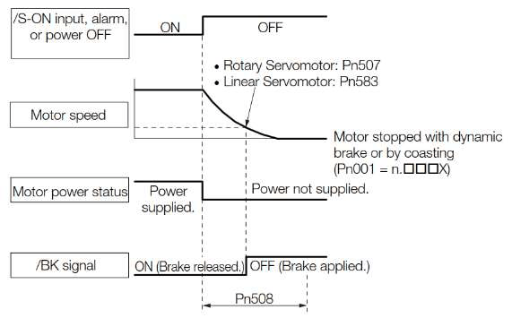
Servomotor after the Power Supply to the Motor Is Stopped
● When the Time Set In Pn508 Elapses after the Power Supply to the Motor Is Stopped
|

5.8 Motor Stopping Methods for Servo OFF and Alarms
You can use the following methods to stop the Servomotor when the servo is turned OFF or an alarm occurs. There are the following four stopping methods.
|
Motor Stopping Method |
Meaning |
|
Stopping by Applying the Dynamic Brake |
The electric circuits are internally connected to stop the Servomotor quickly. |
|
Coasting to a Stop |
The motor stops naturally due to friction during operation. |
|
Zero-speed Stopping |
The speed reference is set to 0 to stop the Servomotor quickly. |
|
Decelerating to a Stop |
Emergency stop torque is used to decelerate the motor to a stop. |
There are the following three conditions after stopping.
|
Status after Stopping |
Meaning |
|
Stopping by Applying the Dynamic Brake |
The electric circuits are internally connected to hold the Servomotor. |
|
Coasting |
The servo driver does not control the Servomotor. (The machine will move in response to a force from the load.) |
|
Zero Clamping |
A position loop is created and the Servomotor remains stopped at a position reference of 0. (The current stop position is held.) |
driver. Use speed input references or position references to start and stop the Servomotor. • If the Servomotor must be stopped by coasting rather than with the dynamic brake when the main circuit power supply or the control power supply is turned OFF before the servo is turned OFF, use a servo driver with the dynamic brake option. • To minimize the coasting distance of the Servomotor to come to a stop when an alarm occurs, zero-speed stopping is the default method for alarms to which it is applicable. However, depending on the |

5.8.1 Stopping Method for Servo OFF
Set the stopping method for when the servo is turned OFF in Pn001 = n.▯▯▯X (Motor Stopping Method for Servo OFF and Group 1 Alarms).
|
Parameter |
Servomotor |
Status after |
When |
Classificati on |
|
|
Pn001 |
n.▯▯▯0 [default |
Dynamic brake* |
Dynamic brake* |
After |
Setup |
|
n.▯▯▯1 |
Coasting |
||||
|
n.▯▯▯2 |
Coasting |
Coasting |
|||
NOTE: If Pn001 is set to n.▯▯▯0 (Stop the motor by applying the dynamic brake) and the Servomotor is stopped or operates at a low
speed, braking force may not be generated, just like it is not generated for coasting to a stop.
5.8.2 Servomotor Stopping Method for Alarms
There are two types of alarms, group 1 (Gr. 1) alarms and group 2 (Gr. 2) alarms. A different parameter is used to set the stopping method for alarms for each alarm type. Refer to the following section to see which alarms are in group 1 and which are in group 2.
Motor Stopping Method for Group 1 Alarms
When a group 1 alarm occurs, the Servomotor will stop according to the setting of Pn001 = n.▯▯▯X. The default setting is to stop by applying the dynamic brake.
Motor Stopping Method for Group 2 Alarms
When a group 2 alarm occurs, the Servomotor will stop according to the settings of the following three parameters. The default setting is for zero clamping.
• Pn001 = n.▯▯▯X (Motor Stopping Method for Servo OFF and Group 1 Alarms) • Pn00A = n.▯▯▯X (Motor Stopping Method for Group 2 Alarms)
• Pn00B = n.▯▯X ▯ (Motor Stopping Method for Group 2 Alarms)
However, during torque control, the group 1 stopping method is always used. If you set Pn00B to n.▯▯1 ▯ (Apply dynamic brake or coast Servomotor to a stop), you can use the same stopping method as group 1. If you are coordinating a number of Servomotors, you can use this stopping method to prevent machine damage that may result because of differences in the stopping method.
The following table shows the combinations of the parameter settings and the resulting stopping methods.
|
Parameter |
ServomotorStoppin g Method |
Status after |
When |
Classificati on |
||
|
Pn00B |
Pn00A |
Pn001 |
||||
|
n.▯▯0▯[default |
— |
n.▯▯▯0 [default |
Zero-speed stop- ping |
Dynamic Brake |
After |
Setup |
|
n.▯▯▯1 |
Coasting |
|||||
|
n.▯▯▯2 |
||||||
|
n.▯▯1▯ |
n.▯▯▯0 [default |
Dynamic Brake |
Dynamic Brake |
|||
|
n.▯▯▯1 |
Coasting |
|||||
|
n.▯▯▯2 |
Coasting |
|||||
|
n.▯▯2▯ |
n.▯▯▯0 [default |
n.▯▯▯0 [default |
Dynamic Brake |
Dynamic Brake |
||
|
n.▯▯▯1 |
Coasting |
|||||
|
n.▯▯▯2 |
Coasting |
|||||
|
n.▯▯▯1 |
n.▯▯▯0 [default |
Motor is |
Dynamic Brake |
|||
|
n.▯▯▯1 |
Coasting |
|||||
|
n.▯▯▯2 |
||||||
|
n.▯▯▯2 |
n.▯▯▯0 [default |
Coasting |
||||
|
n.▯▯▯1 |
||||||
|
n.▯▯▯2 |
||||||
|
n.▯▯▯3 |
n.▯▯▯0 [default |
Motor is |
Dynamic Brake |
|||
|
n.▯▯▯1 |
Coasting |
|||||
|
n.▯▯▯2 |
||||||
|
n.▯▯▯4 |
n.▯▯▯0 [default |
Coasting |
||||
|
n.▯▯▯1 |
||||||
|
n.▯▯▯2 |
NOTE: 1. The setting of Pn00A is ignored if Pn00B is set to n.▯▯0 ▯ or n.▯▯1 ▯.
2. The setting of Pn00A = n.▯▯▯X is enabled for position control and speed control. During torque control, the setting of Pn00A = n.▯▯▯X will be ignored and only the setting of Pn001 = n.▯▯▯X will be used.
5.9 Motor Overload Detection Level
The motor overload detection level is the threshold used to detect overload alarms and overload warnings when the Servomotor is subjected to a continuous load that exceeds the Servomotor ratings.
It is designed to prevent Servomotor overheating.
You can change the detection timing for A.910 warnings (Overload) and A.720 alarms (Continuous Overload). You cannot change the detection level for A.710 alarms (Instantaneous Overload).
5.9.1 Detection Timing for Overload Warnings (A.910)
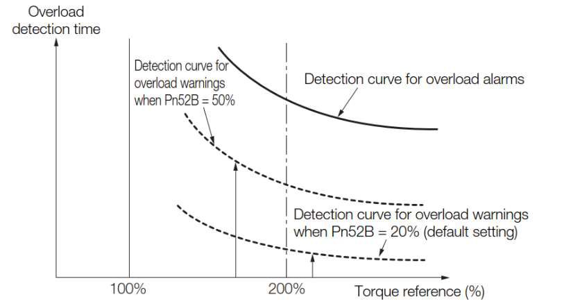
With the default setting for overload warnings, an overload warning is detected in 20% of the time required to detect an overload alarm. You can change the time required to detect an overload warning by changing the setting of the overload warning level (Pn52B). You can increase safety by using overload warning detection as an overload protection function matched to the system.
The following graph shows an example of the detection of overload warnings when the overload warning level (Pn52B) is changed from 20% to 50%. An overload warning is detected in half of the time required to detect an overload alarm.
|
Pn52B |
|
|||||||
|
SetupRange |
SetupUnit |
default setting |
When Enabled |
Classification |
||||
|
0〜100 |
1% |
20 |
immediately |
Setup |
||||
5.9.2 Detection Timing for Overload Alarms (A.720)
If Servomotor heat dissipation is insufficient (e.g., if the heat sink is too small), you can lower the overload alarm detection level to help prevent overheating.
To reduce the overload alarm detection level, change the setting of Pn52C (Base Current Derating at Motor Overload Detection)
|
Pn52C |
|
Torque |
|||||||
|
SetupRange |
SetupUnit |
default setting |
When Enabled |
Classification |
|||||
|
0〜100 |
1% |
100 |
After restart |
Setup |
|||||
An A.720 alarm (Continuous Overload) can be detected earlier to protect the Servomotor from overloading.
Overload detection time
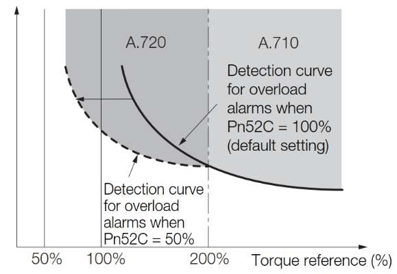
NOTE: The gray areas in the above graph show where A.710 and A.720 alarms occur.
5.10 Electronic Gear Settings
The minimum unit of the position data that is used to move a load is called the reference unit. The reference unit is used to give travel amounts, not in pulses, but rather in distances or other physical units (such as μm or °) that are easier to understand.
The electronic gear is used to convert the travel distances that are specified in reference units to pulses, which are required for actual movements.
With the electronic gear, one reference unit is equal to the workpiece travel distance per refer-ence pulse input to the servo driver. In other words, if you use the servo driver’s electronic gear, pulses can be read as reference units. NOTE: 1. If you set an electronic gear in the host controller, normally set the electronic gear ratio in the servo driver to 1:1. 2. If you enable reference pulse input multiplication switching, the reference unit is defined as the position data that is n times the reference pulses input from the host controller. (“n” is the reference pulse input multiplier.)
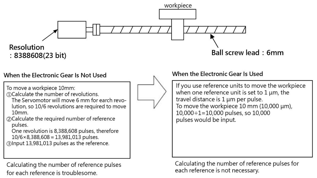
The difference between using and not using the electronic gear is shown below.
Electronic Gear Ratio Settings
Set the electronic gear ratio using Pn20E and Pn210.
|

|
Pn20E |
|
||||||
|
SetupRange |
SetupUnit |
default setting |
When Enabled |
Classification |
|||
|
1~1073741824 |
1 |
1 |
After restart |
Setup |
|||
|
Pn210 |
|
||||||
|
SetupRange |
SetupUnit |
default setting |
When Enabled |
Classification |
|||
|
1~1073741824 |
1 |
1 |
After restart |
Setup |
|||
Calculating the Settings for the Electronic Gear Ratio
If the gear ratio between the Servomotor shaft and the load is given as n/m, where n is the number of load rotations for m Servomotor shaft rotations, the settings for the electronic gear ratio can be calculated as follows:
|
|
× |
m |
|||||
|
Electronic gear ratio |
A |
Pn210 |
Travel distance per load shaft revolution (reference units) |
n |
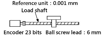
5.10.1 Electronic Gear Ratio Setting Examples
Setting examples are provided in this section.
|
Step |
Description |
Machine Configuration |
||||||||||||||||||||||
|
Ball Screw |
Rotary Table |
Belt and Pulley |
||||||||||||||||||||||
|
|
|
|
||||||||||||||||||||||
|
1 |
Machine |
• Ball screw lead:6mm • Gear ratio:1/1 |
• Rotational angle per rev- olution:360° |
• Pulley dia:100mm |
||||||||||||||||||||
|
2 |
Encoder Resolution |
8388608(23 位) |
8388608(23 位) |
8388608(23 位) |
||||||||||||||||||||
|
3 |
Reference Unit |
0.001 mm (1 µm) |
0.01 mm (10 µm) |
0.005 mm (5 µm) |
||||||||||||||||||||
|
4 |
Travel Distance per |
6 mm/0.001 mm = 6000 |
360°/0.01° = 36000 |
314 mm/0.005 mm = 62800 |
||||||||||||||||||||
|
5 |
Electronic Gear Ratio |
|
|
|
||||||||||||||||||||
|
6 |
Parameter |
Pn20E:8388608 |
Pn20E:838860800 |
Pn20E:419430400 |
||||||||||||||||||||
|
Pn210:6000 |
Pn210:36000 |
Pn210:62800 |
||||||||||||||||||||||
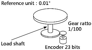
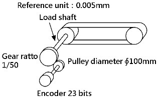
5.11 Resetting the Absolute Encoder
In a system that uses an absolute encoder, the multiturn data must be reset at startup. An alarm related to the absolute encoder (A.810 or A.820) will occur when the absolute encoder must be reset, such as when the power supply is turned ON.
When you reset the absolute encoder, the multiturn data is reset and any alarms related to the absolute encoder are cleared.
Reset the absolute encoder in the following cases
• When an A.810 alarm (Encoder Backup Alarm) occurs
• When an A.820 alarm (Encoder Checksum Alarm) occurs
• When starting the system for the first time
• When you want to reset the multiturn data in the absolute encoder
• When the Servomotor has been replaced
|
|
|
● The multiturn data will be reset to a value between -2 and +2 rotations when the absolute encoder is reset. The reference position of the machine system will change. Adjust the reference position in the host controller to the position that results from resetting the absolute encoder. If the machine is started without adjusting the position in the host controller, unexpected operation may cause personal injury or damage to the machine. |
 CAUTION
NOTE: 1.The multiturn data will always be zero in the following cases. It is never necessary to reset the absolute encoder in these cases. An alarm related to the absolute encoder (A.810 or A.820) will not occur.
• When you use a single-turn absolute encoder
• When the encoder is set to be used as a single-turn absolute encoder (Pn002 = n.▯2 ▯▯)
2.If a batteryless absolute encoder is used, an A.810 alarm (Encoder Backup Alarm) will occur the first time the power is turned ON. After you reset the absolute encoder, the A.810 alarm will no longer occur.
5.11.1 Precautions on Resetting
• You cannot use the /ALM-RST (Alarm Reset) signal from the servo driver to clear the A.810 alarm (Encoder Backup Alarm) or the A.820 alarm (Encoder Checksum Alarm). Always use the operation to reset the absolute encoder to clear these alarms.
• If an A.8 ▯▯ alarm (Internal Encoder Monitoring Alarm) occurs, turn OFF the power supply to reset the alarm. Always check the following before you reset an absolute encoder.
• The parameters must not be write prohibited.
• The servo must be OFF.
5.11.2 Applicable Tools
The following table lists the tools that you can use to reset the absolute encoder
|
Tool |
FA No./Function Name |
|
Panel Operator |
FA008 |
|
ProTuner |
[Encoder Setting−Reset Absolute Encoder] |

5.12 Setting the Regenerative Resistor Capacity
The regenerative resistor consumes regenerative energy that is generated by the Servomotor, e.g., when the Servomotor decelerates.
If an External Regenerative Resistor is connected, you must set Pn600 (Regenerative Resistor Capacity).
|
|
|
• If you connect an External Regenerative Resistor, set Pn600 and Pn603 to suitable values. If a suitable value is not set, A.320 alarms (Regenerative Overload) will not be detected correctly, and the External Regenerative Resistor may be damaged or personal injury or fire may • When you select an External Regenerative Resistor, make sure that it has a suitable capacity. There is a risk of personal injury or fire. |
 WARNING
|
Pn600 |
|
|||||||
|
SetupRange |
SetupUnit |
default setting |
When Enabled |
Classification |
||||
|
0~servo driver’s maximum applica-ble motor capacity |
10W |
0 |
immediately |
Setup |
||||
|
Pn603 |
|
|||||||
|
SetupRange |
SetupUnit |
default setting |
When Enabled |
Classification |
||||
|
0~65535 |
10mΩ |
0 |
immediately |
Setup |
||||
Set the regenerative resistor capacity to a value that is consistent with the allowable capacity of the External Regenerative Resistor. The setting depends on the cooling conditions of the External Regenerative Resistor. • For self-cooling (natural convection cooling): Set the parameter to a maximum 20% of the capacity (W) of the actually installed regenerative resistor.
• For forced-air cooling: Set the parameter to a maximum 50% of the capacity (W) of the actually installed regenerative resistor.
For a self-cooling 100-W External Regenerative Resistor, set Pn600 to 2 (×10 W) (100 W × 20% = 20 W). NOTE: 1. An A.320 alarm will be displayed if the setting is not suitable.
2. The default setting of 0 specifies that the servo driver’s built-in regenerative resistor
• For safety, use an External Regenerative Resistor with a thermoswitch. |

Tip: press ← → to switch chapters, Ctrl+K to search