6.1 I/O Signal Allocations
Functions are allocated to the pins on the I/O signal connector (CN1) in advance. You can change the allocations and the polarity for some of the connector pins. Function allocations and polarity settings are made with parameters.
This section describes the I/O signal allocations.
6.1.1 Input Signal Allocations
Changing Input Signal Allocations
polarity of one of these signals, verify operation and make sure that no safety problems will exist. ● If you allocate two or more signals to the same input circuit, a logical OR of the inputs will be used and all of the allocated signals will operate accordingly. This may result in unexpected operation |

The input signals that you can allocate to the pins on the I/O signal connector (CN1) and the related parameters are given in the following table.(Taking EtherCAT type as an example)
|
Input Signal |
Input Signal Name |
Parameter |
|
P-OT |
Forward Drive Prohibit |
Pn50A = n.X |
|
N-OT |
Reverse Drive Prohibit |
Pn50B = n.X |
|
/P-CL |
Forward External Torque Limit |
Pn50B = n.X |
|
/N-CL |
Reverse External Torque Limit |
Pn50B = n.X |
|
/DEX |
Origin re-positioning deceleration switch input. |
Pn511 = n.X |
|
/EXT1 |
External capture input 1 |
Pn511 = n.X |
|
/EXT2 |
External capture input 2 |
Pn511 = n.X |
|
/EXT3 |
External capture input 3 |
Pn511 = n.X |
|
FSTP |
Forced Stop |
Pn516 = n.X |
◆Relationship between Parameter Settings, Allocated Pins, and Polarities
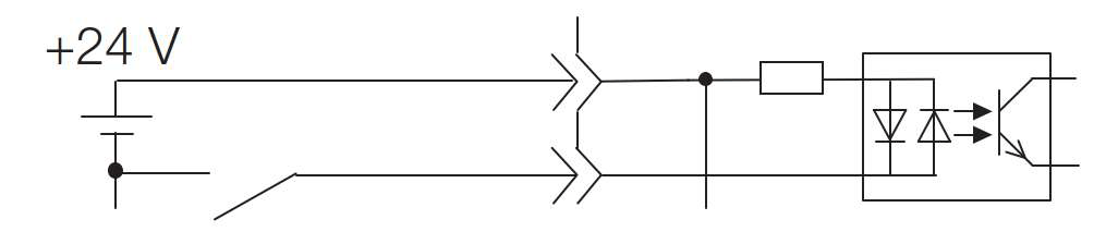
The following table shows the relationship between the input signal parameter settings, the pins on the I/O signal connector (CN1), and polarities.
|
Parameter Setting |
Pin No. |
Description |
|
0 |
IN0(14) |
A reverse signal (a signal with “/” before the signal abbreviation, such as the / S-ON signal) is active when the contacts are ON (closed). A signal that does not have “/” before the signal abbreviation (such as the P-OT signal) is active when the contacts are OFF (open). |
|
1 |
IN1(15) |
|
|
2 |
IN2(16) |
|
|
3 |
IN3(17) |
|
|
IN4(39) |
||
|
5 |
IN5(40) |
|
|
6 |
IN6(41) |
|
|
7 |
IN7(42) |
|
|
8 |
– |
The input signal is not allocated to a connector pin and it is always inactive. Set the parameter to 8 if the signal is not used. |
|
9 |
– |
The input signal is not allocated to a connector pin and it is always inactive. Set the parameter to 9 if the signal is not used. |
Example of Changing Input Signal Allocations
The following example shows reversing the P-OT (Forward Drive Prohibit) signal allocated to CN1-IN1 and the /P-CL (External Torque Limit) signal allocated to CN1-IN3.
Pn50A = n.1▯▯▯ Pn511 = n.▯▯▯3 Before change ↓ ↓
Pn50A = n.3▯▯▯ Pn511 = n.▯▯▯1 After change
Confirming the Allocation Status of Input Signals
You can confirm the allocation status of input signals with the I/O Signal Allocations Window of the Protuner. Refer to the following section for details.
8.3.2 I/O Signals Status Monitor Monitor
6.1.2 Output Signal Allocations
You can allocate the desired output signals on the I/O signal connector (CN1). You set the allocations in the following parameters: Pn50E, Pn50F and Pn510.
Changing Output Signal Allocations
|
• The signals that are not detected are considered to be OFF. For example, the /COIN (Positioning
operation and make sure that no safety problems will exist. • If you allocate more than one signal to the same output circuit, a logical OR of the signals will be output. |

Example of Changing Output Signal Allocations
After disabling the positioning completion output (/COIN) signal assigned to CN1-OUT3, an example of assigning the Servo Ready Output (/S-RDY) signal is shown below.
Pn50E = n.0▯▯3
↓
Pn50E = n.3▯▯0
Confirming the Allocation Status of Output Signals
You can confirm the allocation status of output signals with the I/O Signal Allocations Window of the Protuner. Refer to the following section for details.
8.3.2 I/O Signals Status Monitor Monitor
6.1.3 ALM (Servo Alarm) Signal
This signal is output when the servo driver detects an error.
|

|
Type |
Signal |
Connector Pin No. |
Signal Status |
Meaning |
|
Output |
ALM |
Must be allocated |
ON(closed) |
Normal servo driver status |
|
OFF |
servo driver alarm |
6.1.4 /WARN (Warning) Signal
Both alarms and warnings are generated by the servo driver. Alarms indicate errors in the servo driver for which operation must be stopped immediately. Warnings indicate situations that may results in alarms but for which stopping operation is not yet necessary.
The /WARN (Warning) signal indicates that a condition exists that may result in an alarm.
|
Type |
Signal |
Connector Pin No. |
Signal Status |
Meaning |
|
Output |
/WARN |
Must be allocated |
ON |
Warning |
|
OFF |
Normal status |
NOTE: You must allocate the /WARN signal to use it. Use Pn50F = n.X ▯▯▯ (/WARN (Warning Output) Signal Allocation) to allocate the signal to a connector pin. Refer to the following section for details.
6.1.5 /TGON (Rotation Detection) Signal
The /TGON signal indicates that the Servomotor is operating.
This signal is output when the shaft of the Servomotor rotates at the setting of Pn502. or faster.
|
Type |
Signal |
Connector Pin No. |
Signal Status |
Meaning |
|
輸出 |
/TGON |
Must be allocated |
ON(CLOSED) |
The Servomotor is operating at the setting of Pn502 or faster. |
|
OFF(OPEN) |
The Servomotor operating at a speed that is slower than the setting of Pn502. |
Setting the Rotation Detection Level
Use the following parameter to set the speed detection level at which to output the /TGON signal.
|
Pn502 |
|
|||||||
|
SetupRange |
SetupUnit |
default setting |
When Enabled |
Classification |
||||
|
0~10000 |
1min-1 (RPM) |
20 |
immediately |
Setup |
||||
6.1.6 /S-RDY (Servo Ready) Signal
The /S-RDY (Servo Ready) signal turns ON when the servo driver is ready to accept the /S-ON (Servo ON) input signal.
The /S-RDY signal is turned ON under the following conditions.
• Main circuit power supply is ON.
• There is no hard wire base block state.
• There are no alarms.
• If an absolute encoder is used, the SEN (Absolute Data Request) signal is ON (high level).
• If a Servomotor without a polarity sensor is used, polarity detection has been completed. * • If an absolute encoder is used, the servo driver must be ready to accept the /S-ON (Servo ON) signal and, if the SEN signal is ON (high level), the output of the position data from the absolute encoder to the host controller must have been completed.
*Do not include this condition if the /S-ON (Servo ON) signal is input for the first time after the control power supply was turned ON. In that case, when the first /S-ON signal is input, polarity detection is started immediately and the /S-RDY signal turns ON at the completion of polarity detection.
|
Type |
Signal |
Connector Pin No. |
Signal Status |
Meaning |
|
Output |
/S-RDY |
Must be allocated |
ON(CLOSED) |
Ready to receive the /S-ON (Servo ON) signal. |
|
OFF(OPEN) |
Not ready to receive the /S-ON (Servo ON) signal. |
NOTE: 1. Use Pn50E = n.X ▯▯▯ (/S-RDY (Servo Ready) Signal Allocation) to allocate the /S-RDY signal to another connector pin. Refer to the following section for details.
*1: STO is an optional function
6.1.7 /V-CMP (Speed Coincidence Detection) Signal
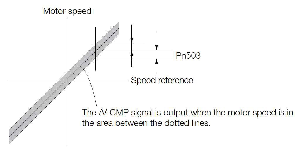
The /V-CMP (Speed Coincidence Output) signal is output when the Servomotor speed is the same as the reference speed. This signal is used, for example, to interlock the servo driver and the host controller. You can use this output signal only during speed control.
The /V-CMP signal is described in the following table.
|
Type |
Signal |
Connector Pin No. |
Signal Status |
Meaning |
|
Output |
/V-CMP |
Must be allocated |
ON |
The speed coincides. |
|
OFF |
The speed does not coincide. |
NOTE: You can use Pn50E = n.▯▯X ▯ (/V-CMP (Speed Coincidence Detection Output) Signal Allocation) to allocate the /V-CMP signal to different output connector pins.
You can set the speed detection width for the /V-CMP signal in Pn503.
|
Pn503 |
|
||||||
|
SetupRange |
Setup Unit |
default setting |
When Enabled |
Classification |
|||
|
0~100 |
1min-1 (RPM) |
10 |
immediately |
Setup |
|||
The signal is output when the difference between the reference speed and motor speed is equal or less than the setting.
NOTE: If Pn503 is set to 100 and the speed reference is 2,000 min-1, the signal would be output when the motor speed is between 1,900 min-1 and 2,100 min-1.
6.1.8 /COIN (Positioning Completion) Signal
The /COIN (Positioning Completion) signal indicates that Servomotor positioning has been completed during position control.
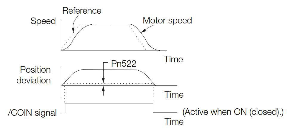
The /COIN signal is output when the difference between the reference position output by the host controller and the current position of the Servomotor (i.e., the position deviation as given by the value of the deviation counter) is equal to or less than the setting of the positioning completed width (Pn522).
Use this signal to check the completion of positioning from the host controller.
|
Type |
Signal |
Connector Pin No. |
Signal Status |
Meaning |
|
Output |
/COIN |
Must be allocated |
ON(CLOSED) |
Positioning has been completed. |
|
OFF(OPEN) |
Positioning has not been completed. |
NOTE: Use Pn50E = n.▯▯▯X (/COIN (Positioning Completion Output) Signal Allocation) to allocate the /COIN signal to other
connector pins. Refer to the following section for details.
Setting the Positioning Completed Width
The /COIN signal is output when the difference between the reference position and the current position (i.e., the position deviation as given by the value of the deviation counter) is equal to or less than the setting of the positioning completed width (Pn522).
|
Pn522 |
|
||||||
|
Setup Range |
Setup Unit |
default setting |
When Enabled |
Classification |
|||
|
0~1073741824 |
1 reference unit |
10 |
immediately |
Setup |
|||
• The setting of the positioning completed width has no effect on final positioning accuracy.
NOTE: If the parameter is set to a value that is too large, the /COIN signal may be output when the position deviation is low during a low-speed operation. If that occurs, reduce the setting until the signal is no longer output.
Setting the Output Timing of the /COIN (Positioning Completion
Output) Signal
You can add a reference input condition to the output conditions for the /COIN signal to change the signal output timing.
If the position deviation is always low and a narrow positioning completed width is used, change the setting of Pn207 = n.X ▯▯▯ (/COIN (Positioning Completion Output) Signal Output Timing) to change output timing for the /COIN signal.。
|
Parameter |
Name |
Description |
When |
Classificati on |
|
|
Pn207 |
n.0▯▯▯[default |
Output Timing of the /COIN (Positioning |
Output the /COIN signal when the absolute value of the position |
After |
Setup |
|
n.1▯▯▯ |
Output the /COIN signal when the absolute value of the position |
||||
|
n.2▯▯▯ |
Output the /COIN signal when the absolute value of the position |
||||
6.1.9 /NEAR (Near) Signal
The /NEAR (Near) signal indicates when positioning completion is being approached.
The host controller receives the NEAR signal before it receives the /COIN (Positioning Completion) signal, it can start preparations for the operating sequence to use after positioning has been completed. This allows you to reduce the time required for operation when positioning is completed.
The NEAR signal is generally used in combination with the /COIN signal.
|
Type |
Signal |
Connector Pin No. |
Signal Status |
Meaning |
|
Output |
/NEAR |
Must be allocated |
ON |
The Servomotor has reached a point near to positioning completion. |
|
OFF |
The Servomotor has not reached a point near to positioning completion. |
NOTE: You must allocate the /NEAR signal to use it. Use Pn510 = n.▯▯▯X (/NEAR (Near) Signal Allocation) to allocate the signal to a connector pin. Refer to the following section for details.
/NEAR (Near) Signal Setting
You set the condition for outputting the /NEAR (Near) signal (i.e., the near signal width) in Pn524 (Near Signal Width). The /NEAR signal is output when the difference between the reference position and the current position (i.e., the position deviation as given by the value of the deviation counter) is equal to or less than the setting of the near signal width (Pn524).
|
Pn524 |
|
||||||
|
SetupRange |
SetupUnit |
default setting |
When Enabled |
Classification |
|||
|
0~1073741824 |
1 reference unit |
1073741824 |
immediately |
Setup |
|||
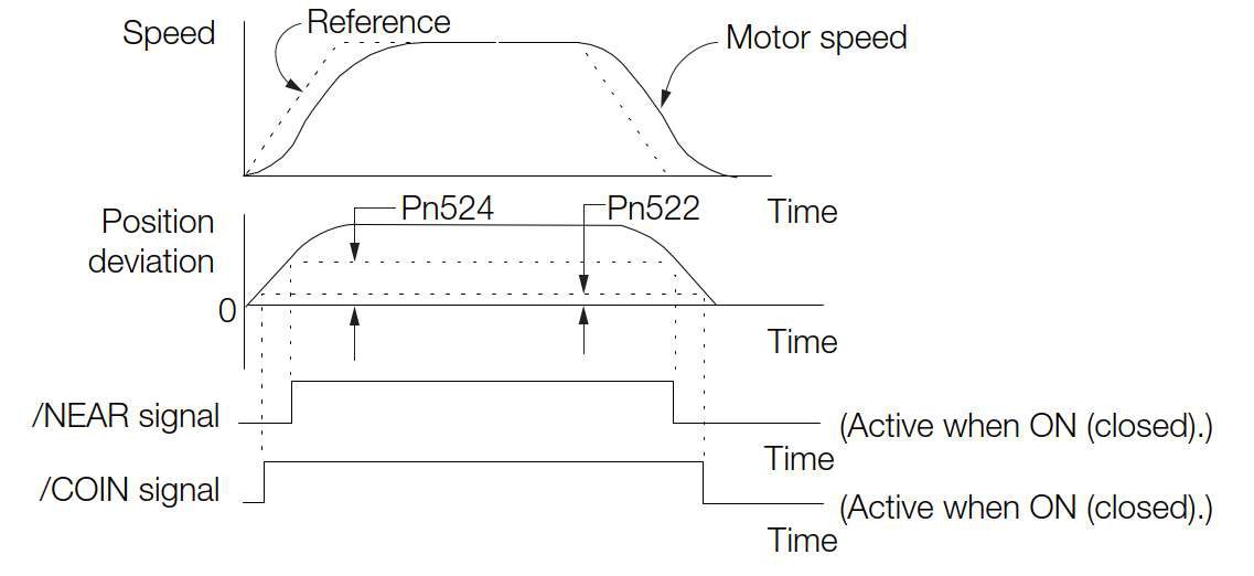
NOTE: Normally, set Pn524 to a value that is larger than the setting of Pn522 (Positioning Completed Width).
6.1.10 Speed Limit during Torque Control
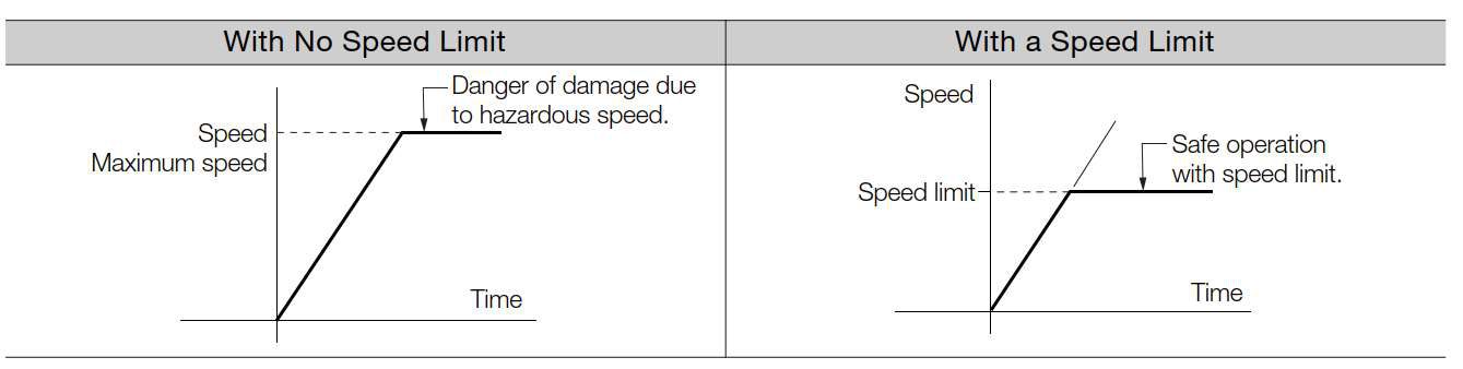
You can limit the speed of the Servomotor to protect the machine.
When you use a Servomotor for torque control, the Servomotor is controlled to output the specified torque, but the motor speed is not controlled. Therefore, if a reference torque is input that is larger than the machine torque, the speed of the Servomotor may increase greatly. If that may occur, use this function to limit the speed.
NOTE: The actual limit of Servomotor speed depends on the load conditions on the Servomotor.
/VLT (Speed Limit Detection) Signal
The signal that is output when the motor speed is being limited by the speed limit is described in the following table.
|
Type |
Signal |
Connector Pin No. |
Signal Status |
Meaning |
|
Output |
/VLT |
Must be allocated |
ON(CLOSED) |
The Servomotor speed is being limited. |
|
OFF(OPEN) |
The Servomotor speed is not being lim- ited. |
NOTE: You must allocate the /VLT signal to use it. Use Pn50F = n.▯▯X ▯ (/VLT (Speed Limit Detection) Signal Allocation) to allocate the signal to a connector pin. Refer to the following section for details.
Selecting the Speed Limit
You set the speed limit to use in Pn002 = n.▯▯X ▯ (Torque Control Option). If you set Pn.002
to n.▯▯1 ▯ (Use V-REF as an external speed limit input), the smaller of the external speed limit and the internal speed limit will be used.
|
Parameter |
Meaning |
When |
Classificati on |
|
|
Pn002 |
n.▯▯0▯ |
System reservedParameter(Don’tSetup) |
After |
Setup |
|
n.▯▯1▯[default setting] |
Use V-REF as an external speed limit input signal and limit the speed with the V-REF input voltage and the setting of Pn300. (Use external speed limiting.) |
|||
◆ Internal Speed Limiting
If you select internal speed limiting for the torque control option (Pn002 = n.▯▯0 ▯), set the speed limit for the motor in Pn407 (Speed Limit during Torque Control) or Pn480 (Speed Limit during Force Control).。
Also set Pn408 = n.▯▯X ▯ (Speed Limit Selection) to specify using the maximum motor speed or the overspeed alarm detection speed as the speed limit. Select the overspeed alarm detection speed to limit the speed to the equivalent of the maximum motor speed.
|
Parameter |
Meaning |
When |
Classificatio n |
|
|
Pn408 |
n.▯▯0▯ |
Use the smaller of the maximum motor speed and the setting of Pn407 or Pn480 as the speed limit. |
After restart |
Setup |
|
n.▯▯1▯ |
Use the smaller of the overspeed alarm detection speed and the setting of Pn407 or Pn480 as the speed limit. |
|||
NOTE: If you are using a Rotary Servomotor, set Pn407 (Speed Limit during Torque Control).
|
Pn407 |
Speed Limit during Torque Control Speed Position |
Torque |
|||||
|
SetupRange |
SetupUnit |
default setting |
When Enabled |
Classification |
|||
|
0~10000 |
1min-1 (RPM) |
10000 |
immediately |
Setup |
|||
NOTE: If the parameter setting exceeds the maximum speed of the Servomotor, the Servomotor’s maximum speed or the
overspeed alarm detection speed will be used.
◆ External Speed Limiting
If you select external speed limiting for the torque control option (Pn002 = n.▯▯X ▯), set the V-REF (Speed Reference Input) signal.
6.2 Operation for Momentary Power Interruptions
Even if the main power supply to the Servo Driver is interrupted momentarily, power supply to the motor (servo ON status) will be maintained for the time set in Pn509 (Momentary Power Interruption Hold Time).
|
Pn509 |
|
Torque |
|||||||
|
Setup Range |
Setup Unit |
default setting |
When Enabled |
Classification |
|||||
|
20~50000 |
1 ms |
20 |
immediately |
Setup |
|||||
If the momentary power interruption time is equal to or less than the setting of Pn509, power supply to the motor will be continued. If it is longer than the setting, power supply to the motor will be stopped. Power will be supplied to the motor again when the main circuit power supply recovers.
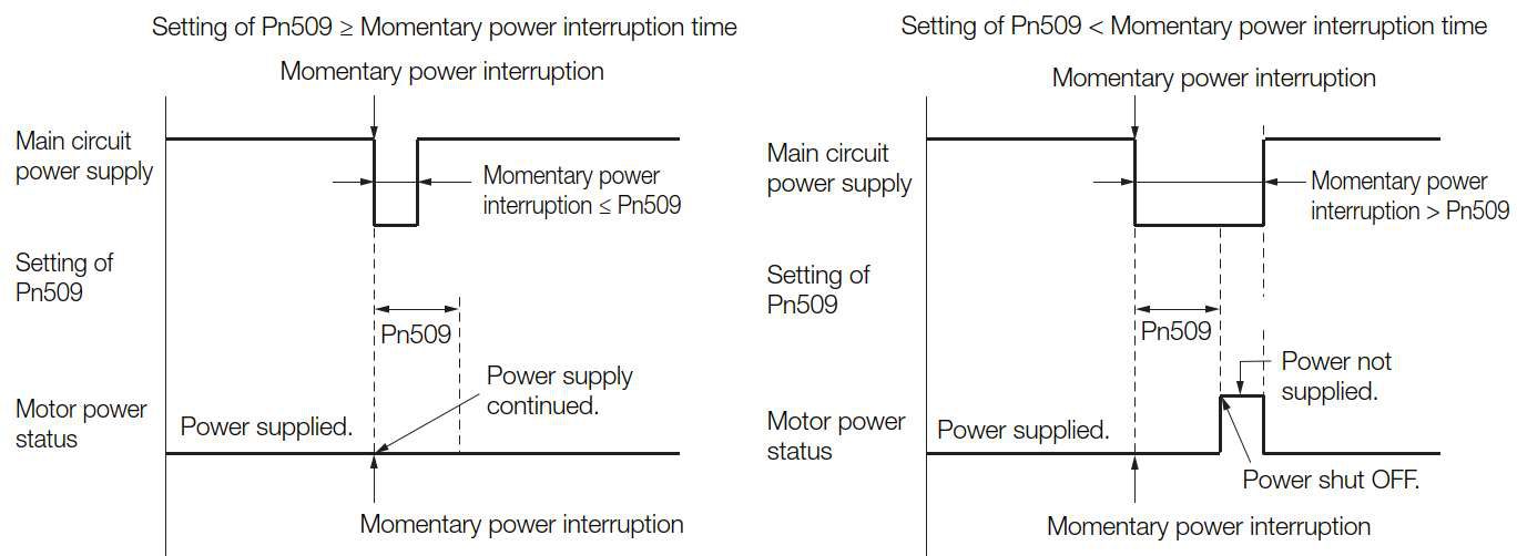
NOTE: 1. If the momentary power interruption time exceeds the setting of Pn509, the /S-RDY (Servo Ready) signal will turn OFF.
2. If uninterruptible power supplies are used for the control power supply and main circuit power supply, the Servo Driver can withstand a power interruption that lasts longer than 50,000 ms.
3. The holding time of the Servo Driver control power supply is approximately 100 ms. If control operations become impossible during a momentary power interruption of the control power supply, the setting of Pn509 will be ignored and the same operation will be performed as for when the power supply is turned OFF normally.
|

6.3 SEMI F47 Function
The SEMI F47 function detects an A.971 warning (Undervoltage) and limits the output current if the DC main circuit power supply voltage to the Servo Driver drops to a specified value or lower because the power was momentarily interrupted, or the main circuit power supply voltage was temporarily reduced.
This function complies with the SEMI F47 standards for semiconductor manufacturing equipment.
You can combine this function with the momentary power interruption hold time (Pn509) to allow the Servomotor to continue operating without stopping for an alarm or without recovery work even if the power supply voltage drops.
Execution Sequence
This function can be executed either with the host controller or with the Servo Driver. Use Pn008 = n.▯▯X ▯ (Function Selection for Undervoltage) to specify whether the function is executed by the host controller or by the Servo Driver.
◆Execution with the Host Controller (Pn008 = n.▯▯1 ▯)
The host controller limits the torque in response to an A.971 warning (Undervoltage). The host controller removes the torque limit after the Undervoltage warning is cleared.
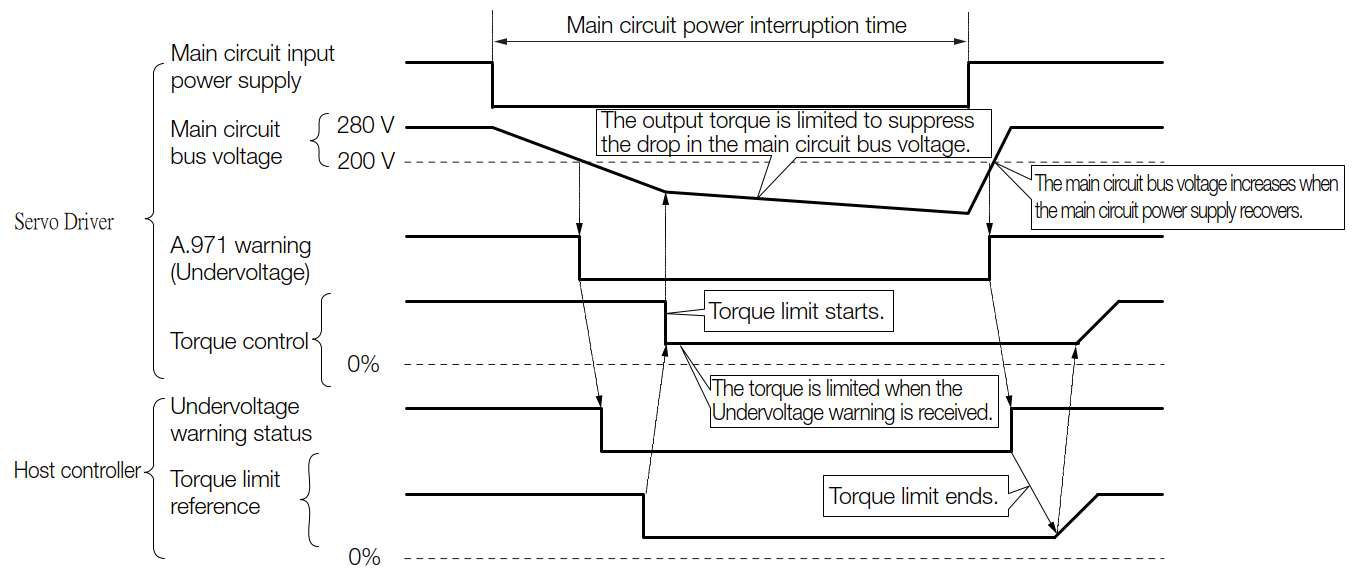
◆Execution with the Servo Driver (Pn008 = n.▯▯2 ▯)
The torque is limited in the Servo Driver in response to an Undervoltage warning.
The Servo Driver controls the torque limit for the set time after the Undervoltage warning is cleared.
The Setting of Undervoltage WARNING(A.971)
|
Parameter |
Meaning |
When |
Classificatio n |
|
|
Pn008 |
n.▯▯0▯ |
Do not detect undervoltage. |
After restart |
Setup |
|
n.▯▯1▯ |
Detect undervoltage warning and limit torque at host controller. |
|||
|
n.▯▯2▯ |
Detect undervoltage warning and limit torque with Pn424 and Pn425 (i.e., only in Servo Driver). |
|||
◆Related Parameters
The following parameters are related to the SEMI F47 function.
|
Pn424 |
|
|||||||
|
Setup Range |
Setup Unit |
default setting |
When Enabled |
Classification |
||||
|
10~100 |
1% * |
50 |
immediately |
Setup |
||||
|
Pn425 |
|
|||||||
|
Setup Range |
Setup Unit |
default setting |
When Enabled |
Classification |
||||
|
10~1000 |
1 ms |
100 |
immediately |
Setup |
||||
|
Pn509 |
|
|||||||
|
Setup Range |
Setup Unit |
default setting |
When Enabled |
Classification |
||||
|
20~50000 |
1 ms |
20 |
immediately |
Setup |
||||
* Set a percentage of the motor rated torque.
NOTE: If you will use the SEMI F47 function, set the time to 1,000 ms.
|
• This function handles momentary power interruptions for the voltage and time ranges stipulated in SEMI F47. An uninterruptible power supply (UPS) is required as a backup for momentary power interruptions that exceed these voltage and time ranges. • Set the host controller or Servo Driver torque limit so that a torque reference that exceeds the specified acceleration torque will not be output when the power supply for the main circuit is restored. • For a vertical axis, do not limit the torque to a value that is lower than the holding torque. • This function limits torque within the range of the Servo Driver’s capability for power interruptions. It is not intended for use under all load and operating conditions. Set the parameters while monitoring operation on the actual machine. |
|
• You can set the momentary power interruption hold time to increase the amount of time from when the power supply is turned OFF until power supply to the motor is stopped. To stop the power supply to the motor immediately, use the /S-ON (Servo ON) signal. |
6.4 Setting the Motor Maximum Speed
You can set the maximum speed of the Servomotor with the following parameter.
|
Pn316 |
|
Torque |
|||||||
|
Setup Range |
Setup Unit |
default setting |
When Enabled |
Classification |
|||||
|
0~65535 |
1min-1 (RPM) |
10000 |
After restart |
Setup |
|||||
You can achieve the following by lowering the maximum speed of the Servomotor.
• If the Servomotor speed exceeds the setting, an A.510 alarms (Overspeed) will occur.
Changing the setting of the parameter is effective in the following cases.
• To protect the machine by stopping machine operation with an alarm when the set speed is reached or exceeded • To limit the speed so that the load is driven beyond the allowable moment of inertia Refer to relevant manual from the following list for the relationship between the speed and the allowable moment of inertia.時
6.5 Encoder Divided Pulse Output
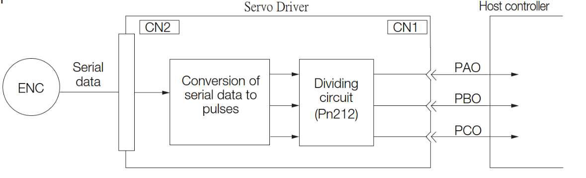
The encoder divided pulse output is a signal that is output from the encoder and processed inside the servo driver. It is then output externally in the form of two-phase pulse signals (phases A and B) with a 90° phase differential. At the host controller, it is used as the position feedback.
The following table describes the signals and output phase forms.
6.5.1 Encoder Divided Pulse Output Signals
|
Type |
Signal |
Connector Pin No. |
Name |
Remarks |
|||||||||||
|
Output |
PAO+ |
CN1-19 |
Output, |
This encoder divided pulse output pins output the number of pulses per Servomotor resolution that is set in Pn212 (Number of Encoder Output Pulses). The phase difference between phase A and phase B is an electric angle of 90°. |
|||||||||||
|
PAO- |
CN1-20 |
||||||||||||||
|
PBO+ |
CN1-21 |
Output, |
|||||||||||||
|
PBO- |
CN1-22 |
||||||||||||||
|
PCO+ |
CN1-23 |
Output, |
|
||||||||||||
|
PCO- |
CN1-24 |
||||||||||||||
Output Phase Forms
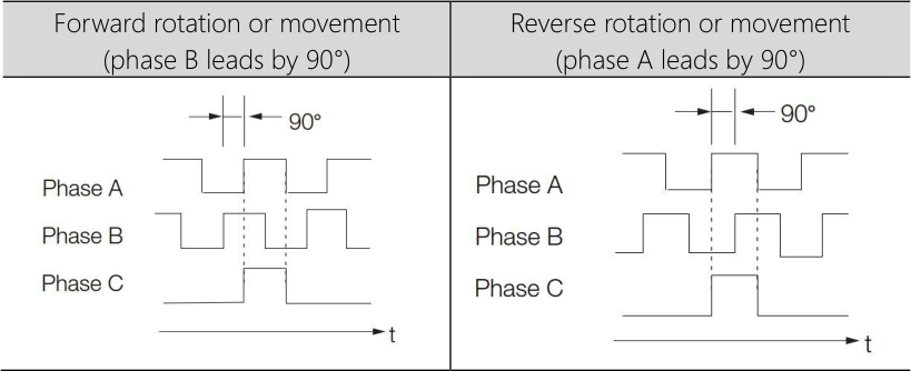
NOTE: The pulse width of the origin within one encoder rotation depends on the setting of number of encoder output pulses (Pn212) or the encoder output resolution (Pn281). It is the same as the width of phase A.
Even for reverse operation (Pn000 = n.▯▯▯1), the output phase form is the same as shown above.
|

6.5.2 Setting for the Encoder Divided Pulse Output
This section describes the setting for the encoder divided pulse output for a Rotary Servomotor or Linear Servomotor.
If you will use a Rotary Servomotor, set the number of encoder output pulses (Pn212)
|
Pn212 |
|
|||||||
|
Setup Range |
Setup Unit |
default setting |
When Enabled |
Classification |
||||
|
16~1073741824 |
1 pitch/Rev |
2500 |
After restart |
Setup |
||||
The number of pulses from the encoder per rotation are processed inside the servo driver, divided by the setting of Pn212, and then output.
Set the number of encoder divided output pulses according to the system specifications of the machine or host controller.
The setting of the number of encoder output pulses is limited by the resolution of the encoder.
NOTE: 1. The setting range of the number of encoder output pulses (Pn212) depends on the resolution of the Servomotor encoder. An A.041 alarm (Encoder Output Pulse Setting Error) will occur if the above setting conditions are not met.
Correct setting example: Pn212 can be set to 25,000 [P/Rev].Incorrect setting example: Pn212 cannot be set to 25,001 (P/Rev) because the setting increment in the above table is not used.
2. The upper limit of the pulse frequency is approximately 1.6 Mpps. The Servomotor speed will be limited if the setting of the number of encoder output pulses is too high.
An A.511 alarm (Encoder Output Pulse Overspeed) will occur if the upper limit of the motor speed is exceeded.
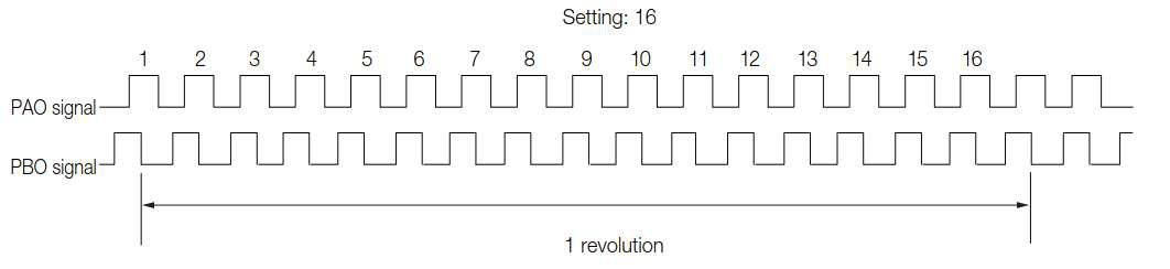
Output example: An output example is given below for the PAO (Encoder Pulse Output Phase A) signal and the PBO (Encoder Pulse Output Phase B) signal when Pn212 is set to 16 (16 pulses output per revolution).
6.6 The Software Limit Function
The software limits is that, when the mechanical movement exceeds the software limit values without using limit signals (P-OT, N-OT), it performs a forced stop just like over-traveling.
When using software limits, the following setup is required:。
• Enable the software limit function
• Set the software limit values.
6.6.1 The Validity/Invalidity of The Software Limit Function
The validity/invalidity of the software limit function is set through Pn801=n. ▯▯▯X (software limit function). The software limit function is effective in the following cases (when the mechanical coordinate system origin is confirmed). In other situations, even if the software limit range is exceeded, the software limit function will not activate:
• After completing the ZRET command
• After executing the POS_SET command with REFE = 1
• After completing the sensor ON (SENS_ON) command when using an absolute encoder.
|
Parameter |
Meaning |
When |
Classification |
|
|
Pn801 |
n.▯▯▯0 |
Enable the software limit of both positive and negative direction. |
immediately |
Setup |
|
n.▯▯▯1 |
Disable the software limit of positive direction. |
|||
|
n.▯▯▯2 |
Disable the software limit of negative direction. |
|||
|
n.▯▯▯3 |
Disable the software limit of both positive and negative direction.。 |
|||
6.6.2 Setup of Software Limit Value
Set up the software limit values for the positive and negative directions.
According to the setup direction, ensuring that "negative direction software limit value < positive direction software limit value.
|
Pn804 |
|
||||||
|
Setup Range |
Setup Unit |
default setting |
When Enabled |
Classification |
|||
|
-1073741823~1073741823 |
1 Unit |
1073741823 |
immediately |
Setup |
|||
|
Pn806 |
|
||||||
|
Setup Range |
Setup Unit |
default setting |
When Enabled |
Classification |
|||
|
-1073741823~1073741824 |
1 Unit |
-1073741823 |
immediately |
Setup |
|||
6.6.3 The software Limit Check
When sending commands such as POSING or INTERPOLATE to move to the target position, the software limit check is performed. If the target position exceeds the software limit values, the system will decelerate and stop at the position set in the software limits.
|
Parameter |
Meaning |
When Enabled |
Classification |
|
|
Pn801 |
n.▯0▯▯ |
With software limit check |
immediately |
Setup |
|
n.▯▯▯1 |
Without software limit check |
|||
6.7 Selecting Torque Limits
You can limit the torque that is output by the servomotor.
There are four different ways to limit the torque. These are described in the following table.
|
Limit Method |
Outline |
Control Method |
備註 |
|
Internal Torque Limits |
The torque is always limited with the setting of a parameter. |
Speedcontrol Positioncontrol Torquecontrol |
|
|
External TorqueLimits |
The torque is limited with an input signal from the host computer. |
||
|
Torque Limuts Based on TLIM* |
Torque limits can be configured through the TLIM command. |
Speedcontrol Positioncontrol |
|
|
Torque Limits Based on The P_CL & N_CL of Output signals |
Torque limits can be configured through the P_CL & N_CL command. |
NOTE: Even if the setup value exceeds the maximum torque of the servo motor being used, the actual torque will be limited to within the maximum torque of the servo motor.
6.7.1 Internal Torque Limits
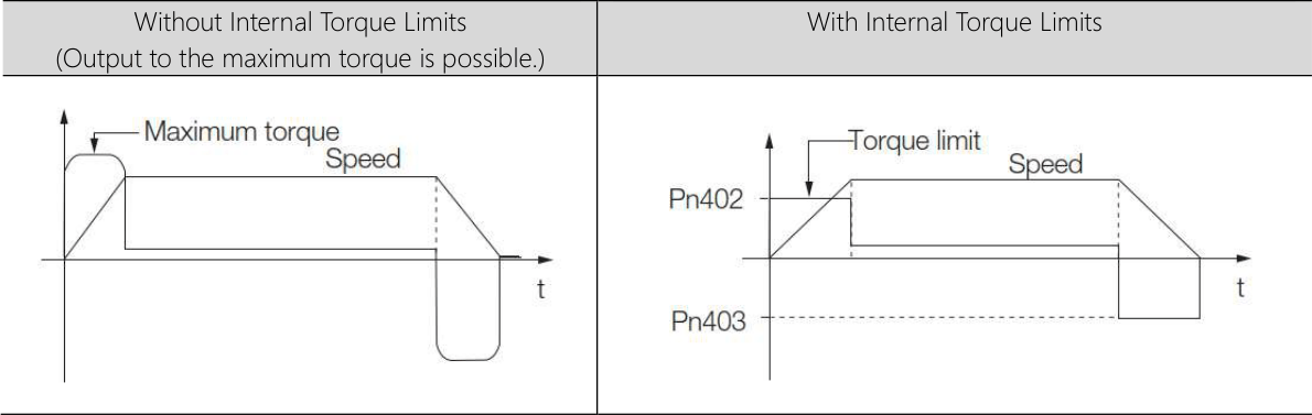
f you use internal torque limits, the maximum output torque will always be limited to the specified forward torque limit (Pn402) and reverse torque limit (Pn403).
|
Pn402 |
|
|||||||
|
Setup Range |
Setup Unit |
default setting |
When Enabled |
Classification |
||||
|
0~800 |
1%* |
800 |
immediately |
Setup |
||||
|
Pn403 |
|
|||||||
|
Setup Range |
Setup Unit |
default setting |
When Enabled |
Classification |
||||
|
0~800 |
1%* |
800 |
immediately |
Setup |
||||
* Set a percentage of the rated motor torque.
NOTE: If the setting of Pn402 or Pn403 is too low, the torque may be insufficient for acceleration or deceleration of the Servomotor.
6.7.2 External Torque Limits
You can limit the torque only when required by the operating conditions of the machine by turning a signal ON and OFF. You can use this for applications such as stopping on physical contact, or holding a workpiece with a robot.
External Torque Limit Reference Signals
The /P-CL (Forward External Torque Limit) and /N-CL (Reverse External Torque Limit) signals are used as the external torque limit reference signals. The /P-CL signal is used for the forward torque limit and the /N-CL signal is used for the reverse torque limit.
|
Type |
Signal |
Connector Pin No. |
Signal Status |
Meaning |
|
Input |
/P-CL |
Must be allocated |
ON(CLOSED) |
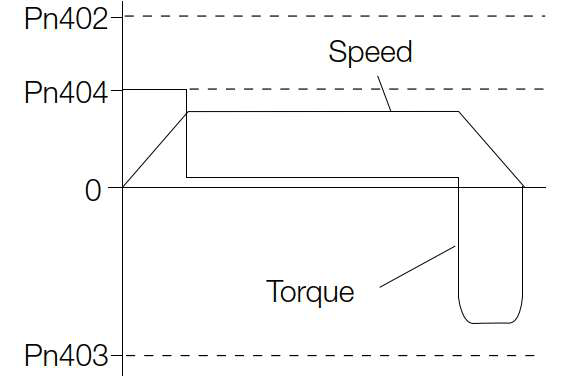
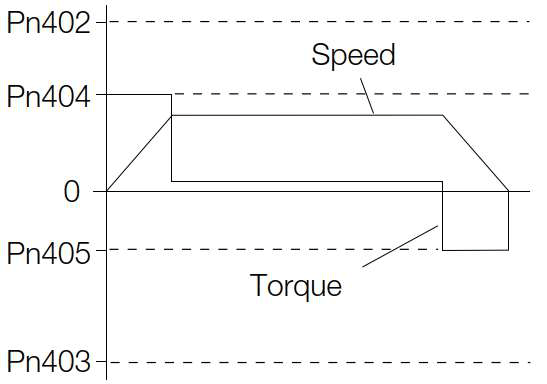
Applies the forward external torque limit. The torque is limited to the smaller of the settings of Pn402 and Pn404. |
|
OFF(OPEN) |
Cancels the forward external torque limit. The torque is limited to the setting of Pn402. |
|||
|
Input |
/N-CL |
Must be allocated |
ON(CLOSED) |
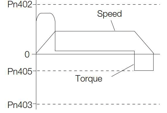
Applies the reverse external torque limit. The torque is limited to the smaller of the set- tings of Pn403 and Pn405. |
|
OFF(OPEN) |
Cancels the reverse external torque limit. The torque is limited to the setting of Pn403. |
NOTE: You can use the following parameters to allocate the /P-CL and /N-CL signals to other terminals.
• Pn50B = n.▯X ▯▯ (/P-CL (Forward External Torque Limit Input) Signal Allocation)
• Pn50B = n.X ▯▯▯ (/N-CL (Reverse External Torque Limit Input) Signal Allocation)
Setting the Torque Limits
The parameters that are related to setting the torque limits are given below.
If the setting of Pn402 (Forward Torque Limit), Pn403 (Reverse Torque Limit), Pn404 (Forward External Torque Limit), or Pn405 (Reverse External Torque Limit) is too low, the torque may be insufficient for acceleration or deceleration of the Servomotor.
|
Pn402 |
|
Torque |
||||||||
|
Setup Range |
Setup Unit |
default setting |
When Enabled |
Classification |
||||||
|
0~800 |
1%* |
800 |
immediately |
Setup |
||||||
|
Pn403 |
|
|||||||||
|
Setup Range |
Setup Unit |
default setting |
When Enabled |
Classification |
||||||
|
0~800 |
1%* |
800 |
immediately |
Setup |
||||||
|
Pn404 |
|
Torque |
||||||||
|
Setup Range |
Setup Unit |
default setting |
When Enabled |
Classification |
||||||
|
0~800 |
1%* |
100 |
immediately |
Setup |
||||||
|
Pn405 |
|
|||||||||
|
Setup Range |
Setup Unit |
default setting |
When Enabled |
Classification |
||||||
|
0~800 |
1%* |
100 |
immediately |
Setup |
||||||
* Set a percentage of the rated motor torque.
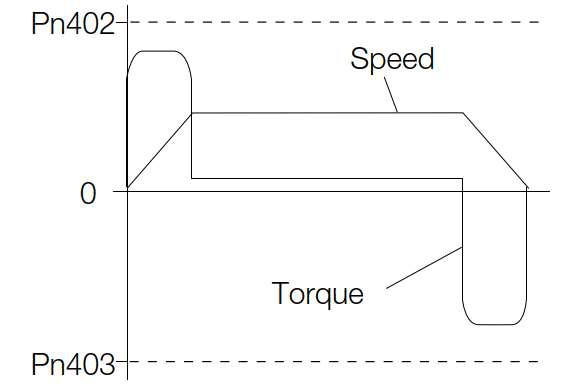
Changes in the Output Torque for External Torque Limits
The following table shows the changes in the output torque when the internal torque limit is set to 800%. In this example, the Servomotor direction is set to Pn000 = n.▯▯▯0 (Use CCW as the forward direction).
|
Singal |
/P-CL |
||
|
Status |
OFF |
ON |
|
|
/N-CL |
OFF |
|
|
|
ON |
|
|
|
6.7.3 /CLT (Torque Limit Detection) Signal
This section describes the /CLT signal, which indicates the status of limiting the motor output torque.
|
Type |
Signal |
Connector Pin No. |
Signal Status |
Meaning |
|
Input |
/CLT |
Must be allocated |
ON(CLOSED) |
The motor output torque is being limited. |
|
OFF(OPEN) |
The motor output torque is not being limited. |
NOTE: You must allocate the /CLT signal to use it. Use Pn50F = n.▯▯▯X (/CLT (Torque Limit Detection Output) Signal Allocation) to allocate the signal to a connector pin. Refer to the following section for details.
6.8 Absolute Encoders
The absolute encoder records the current position of the stop position even when the power supply is OFF.
With a system that uses an absolute encoder, the host controller can monitor the current position.
Therefore, it is not necessary to perform an origin return operation when the power supply to the system is turned ON. There are four types of encoders for Rotary Servomotors. The usage of the encoder is specified in Pn002 = n.▯X ▯▯.
•Parameter Settings When Using an Incremental Encoder
|
Parameter |
Meaning |
When |
Classification |
|
|
Pn002 |
n.▯0▯▯ |
Use the encoder as an incremental encoder. A battery is not required. |
After restart |
Setup |
|
n.▯1▯▯ |
Use the encoder as an incremental encoder. A battery is not required. |
|||
|
n.▯2▯▯ |
Use the encoder as a single-turn absolute encoder. A battery is not required. |
|||
• Parameter Settings When Using a Single-Turn Absolute Encoder
|
Parameter |
Meaning |
When |
Classification |
|
|
Pn002 |
n.▯0▯▯ |
Use the encoder as a single-turn absolute encoder. A battery is not required. |
After restart |
Setup |
|
n.▯1▯▯ |
Use the encoder as an incremental encoder. A battery is not required. |
|||
|
n.▯2▯▯ |
Use the encoder as a single-turn absolute encoder. A battery is not required. |
|||
• Parameter Settings When Using a Batteryless Multiturn Absolute Encoder
|
Parameter |
Meaning |
When |
Classification |
|
|
Pn002 |
n.▯0▯▯ |
Use the encoder as a multiturn absolute encoder. A battery is required. |
After restart |
Setup |
|
n.▯1▯▯ |
Use the encoder as an incremental encoder. A battery is not required. |
|||
|
n.▯2▯▯ |
Use the encoder as a single-turn absolute encoder. A battery is not required. |
|||
|
|
|
• Install a battery at either the host controller or on the Encoder Cable. If you install batteries both at the host controller and on the Encoder Cable at the same time, you will create a loop circuit between the batteries, resulting in a risk of damage or burning. |
 NOTICE
6.9 Forcing the Motor to Stop
You can force the Servomotor to stop for a signal from the host controller or an external device.
To force the motor to stop, you must allocate the FSTP (Forced Stop Input) signal in Pn516 =n.▯▯▯X. You can specify one of the following stopping methods: dynamic brake (DB), coasting to a stop, or decelerating to a stop.
NOTE: Forcing the motor to stop is not designed to comply with any safety standard. In this respect, it is different from the hard wire base block (HWBB).
NOTE: When a forced stop is performed, the panel display will display FST and the Digital Operator will display FSTP.
6.9.1 FSTP (Forced Stop Input) Signal
|
Type |
Signal |
Connector Pin No. |
Signal Status |
Meaning |
|
Input |
FSTP |
Must be allocated |
ON(CLOSED) |
Drive is enabled (normal operation). |
|
OFF(OPEN) |
The motor is stopped. |
NOTE: You must allocate the FSTP signal to use it. Use Pn516 = n.▯▯▯X (FSTP (Forced Stop Input) Signal Allocation) to allocate the FSTP signal to a connector pin. Refer to the following section for details.
6.9.2 Stopping Method Selection for Forced Stops
Use Pn00A = n.▯▯X ▯ (Stopping Method for Forced Stops) to set the stopping method for forced stops.
|
Parameter |
Meaning |
When |
Classificati on |
|
|
Pn00A |
n.▯▯0▯ |
Apply the dynamic brake or coast the motor to a stop (use the stopping method set in Pn001 = n. X). |
After |
Setup |
|
n.▯▯1▯[default setting] |
Decelerate the motor to a stop using the torque set in Pn406 as the maximum torque. Use the setting of Pn001 = n.▯▯▯X for the status after stopping. |
|||
|
n.▯▯2▯ |
Decelerate the motor to a stop using the torque set in Pn406 as the maximum torque and then let the motor coast. |
|||
|
n.▯▯3▯ |
Decelerate the motor to a stop using the deceleration time set in Pn30A. Use the setting of Pn001 = n.▯▯▯X for the status after stopping. |
|||
|
n.▯▯4▯ |
Decelerate the motor to a stop using the deceleration time set in Pn30A and then let the motor coast. |
|||
NOTE: You cannot decelerate a Servomotor to a stop during torque control. For torque control, the Servomotor will be stopped with the dynamic braking or coast to a stop according to the setting of Pn001 = n.▯▯▯X (Motor Stopping Method for Servo OFF and Group 1 Alarms).
Stopping the Servomotor by Setting Emergency Stop Torque (Pn406)
To stop the Servomotor by setting emergency stop torque, set Pn406 (Emergency Stop Torque).
If Pn00A = n.▯▯X ▯ is set to 1 or 2, the Servomotor will be decelerated to a stop using the torque set in Pn406 as the maximum torque.
The default setting is 800%. This setting is large enough to allow you to operate the Servomotor at the maximum torque. However, the maximum emergency stop torque that you can actually use is the maximum torque of the Servomotor.
|
Pn406 |
|
|||||||
|
Setup Range |
Setup Unit |
default setting |
When Enabled |
Classification |
||||
|
0~800 |
1%* |
800 |
immediately |
Setup |
||||
* 相對於馬達額定Torque 的百分比。
Stopping the Servomotor by Setting the Deceleration Time for Servo
OFF and Forced Stops (Pn30A)
To specify the Servomotor deceleration time and use it to stop the Servomotor, set Pn30A (Deceleration Time for Servo OFF and Forced Stops).
|
Pn30A |
|
||||||
|
Setup Range |
Setup Unit |
default setting |
When Enabled |
Classification |
|||
|
0~10000 |
1 ms |
0 |
immediately |
Setup |
|||
If you set Pn30A to 0, the Servomotor will be stopped with a zero speed.
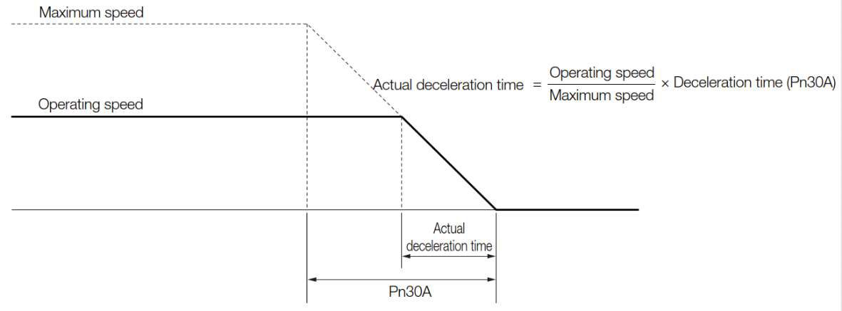
The deceleration time that you set in Pn30A is the time to decelerate the Servomotor from the maximum motor speed.
6.9.3 Resetting Method for Forced Stops
This section describes the reset methods that can be used after stopping operation for an FSTP (Forced Stop Input) signal.
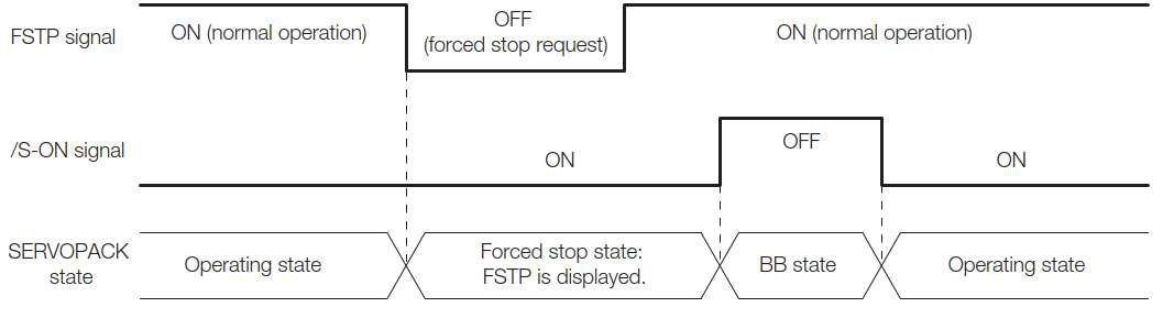
If the FSTP (Forced Stop Input) signal is OFF and the /S-ON (Servo ON Input) signal is input, the forced stop state will be maintained even after the FSTP signal is turned ON.
Turn OFF the /S-ON signal to place the servo driver in the base block (BB) state and then turn ON the /S-ON signal again.
Tip: press ← → to switch chapters, Ctrl+K to search