9.1 Inspections and Part Replacement
This section describes inspections and part replacement for SERVO DRIVER.
9.1.1 Inspections
Perform the inspections given in the following table at least once every year for the servo driver. Daily inspections are not required.
|
Item |
Frequency |
Inspection |
Correction |
|
Exterior |
At least once a year |
Check for dust, dirt, and oil on the surfaces. |
Clean with compressed air or a cloth. |
|
Loose Screws |
Check for loose terminal block and connector screws and for other |
Tighten any loose screws or other loose parts. |
9.1.2 Replacing the Battery
If the battery voltage drops to approximately 3V or less, an A.830 alarm (Encoder Battery Alarm) or an A.930 warning (Absolute Encoder Battery Error) will be displayed.
Battery Alarm/Warning Selection
Whether to display an alarm or a warning is determined by the setting of Pn008 = n.▯▯▯X (Low Battery Voltage Alarm/Warning Selection)..
|
Parameter |
Function |
When |
Classification |
|
|
Pn008 |
n.▯▯▯0 |
Output alarm for low battery voltage (A.830). |
After restart |
Setup |
|
n.▯▯▯1 |
Output warning for low battery voltage (A.930). |
|||
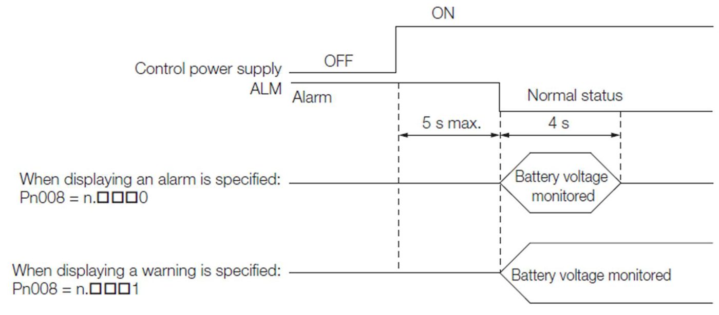
• Pn008=n.▯▯▯0
•The ALM (Servo Alarm) signal is output for up to five seconds when the control power supply is turned ON, and then the battery voltage is monitored for four seconds.
No alarm will be displayed even if the battery voltage drops below the specified value after these four seconds.
• Pn008=n.▯▯▯1
•The ALM (Servo Alarm) signal is output for up to five seconds when the control power supply is turned ON, and then the battery voltage is monitored continuously.
◆When Using an Encoder Cable with a Battery Case
1.Turn ON only the control power supply to the servo driver.
|

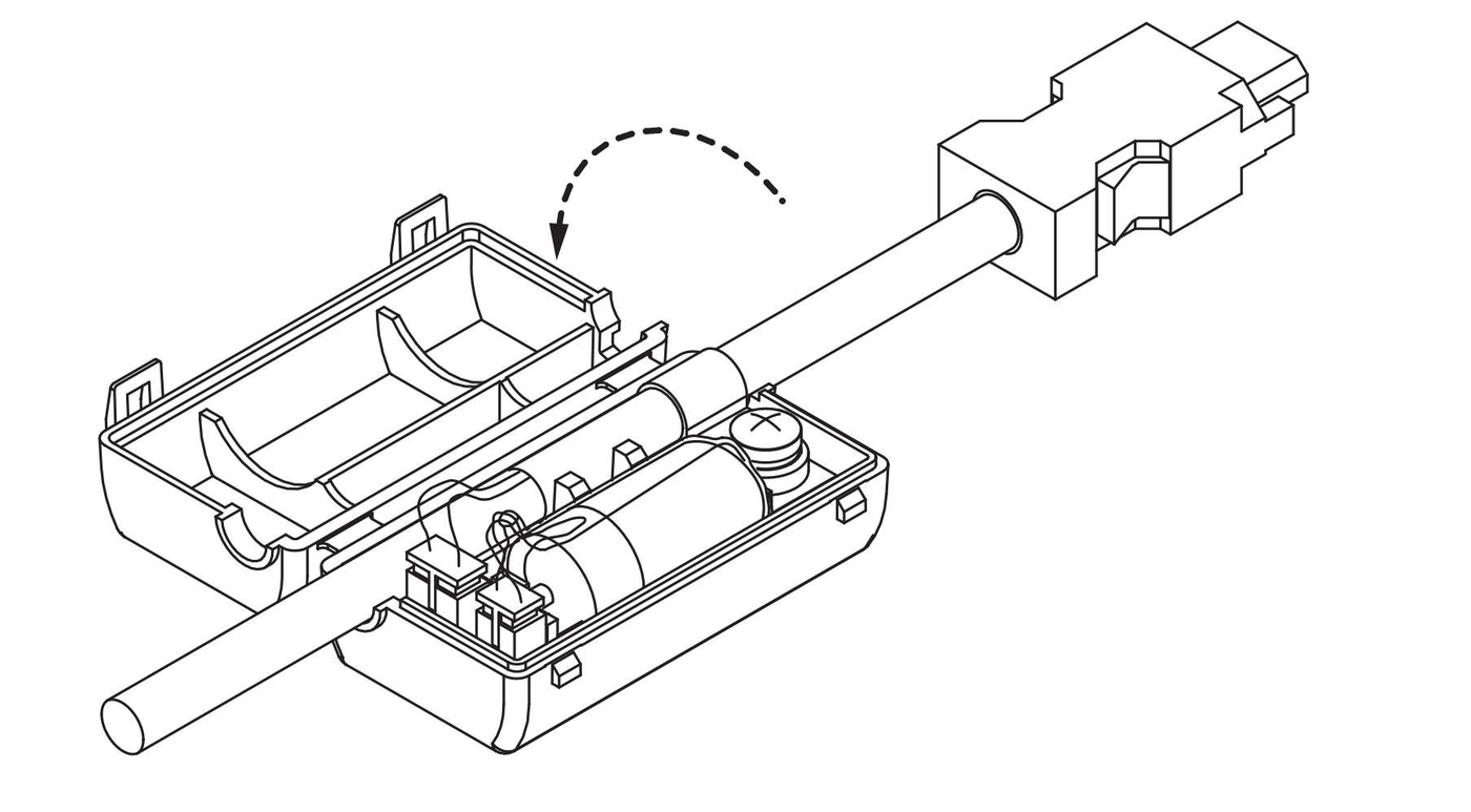
2.Open the cover of the Battery Case
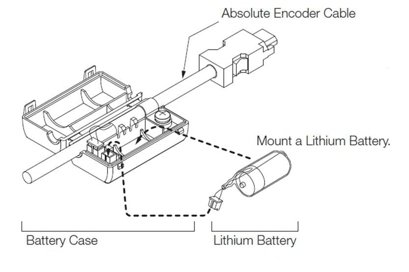
3.Remove the old Battery and mount a new Battery.
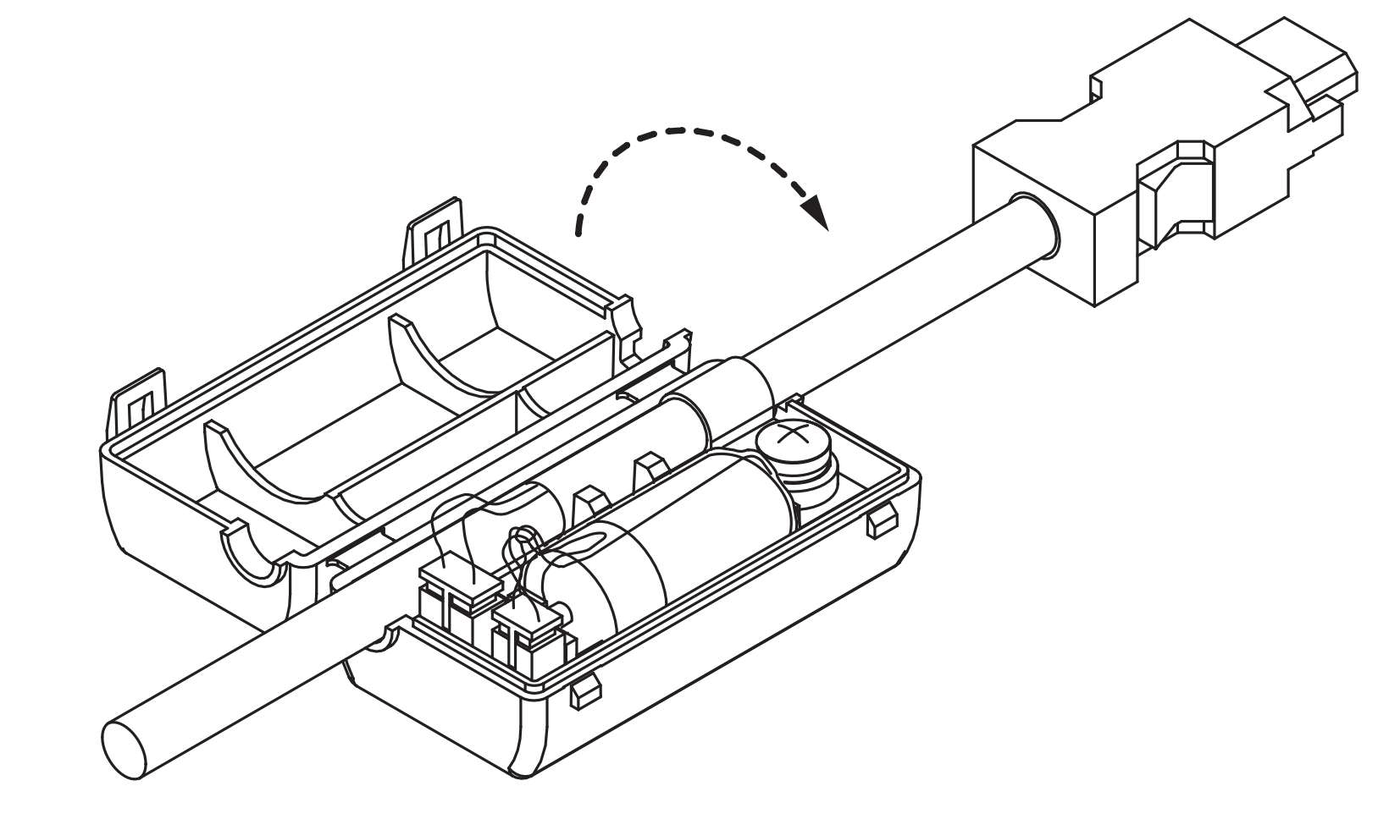
4.Close the cover of the Battery Case.
5.Turn OFF the power supply to the servo driver to clear the A.830 alarm (Encoder Battery Alarm).
6.Turn ON the power supply to the servo driver.
7.Make sure that the alarm has been cleared and that the servo driver operates normally.
9.2 Alarm Displays
If an error occurs in the servo driver, an alarm number will be displayed on the panel display. Example: If an A.020 alarm occurs,
“020” will flash on the display:
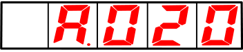
9.2.1 List of Alarms
The list of alarms gives the alarm name, alarm meaning, alarm stopping method, alarm reset possibility, and alarm code output in order of the alarm numbers.
Alarm Reset Possibility
Yes: You can use an alarm reset to clear the alarm. However, this assumes that the cause of the alarm has been removed.
No: You cannot clear the alarm.
List of Alarms
|
Alarm |
Alarm Name |
Alarm Meaning |
Servomotor Stopping |
Alarm |
|
A.020 |
Parameter Checksum Error |
There is an error in the parameter data in the servo driver. |
Gr.1 |
No |
|
A.021 |
Parameter Format Error |
There is an error in the parameter data format in the servo driver. |
Gr.1 |
No |
|
A.022 |
System Checksum Error |
There is an error in the parameter data in the servo driver. |
Gr.1 |
No |
|
A.030 |
Main Circuit DetectorError |
There is an error in the detection data for the main circuit. |
Gr.1 |
Yes |
|
A.040 |
Parameter Setting Error |
A parameter setting is outside of the setting range. |
Gr.1 |
No |
|
A.042 |
Parameter Combination Error |
The combination of some parameters exceeds the setting range. |
Gr.1 |
No |
|
A.050 |
Combination Error |
The capacities of the servo driver and Servomotor do not match. |
Gr.1 |
Yes |
|
A.051 |
Unsupported Device Alarm |
An unsupported device was connected. |
Gr.1 |
No |
|
A.0b0 |
Invalid Servo ON Command Alarm |
The /S-ON (Servo ON) signal was input from the host controller |
Gr.1 |
Yes |
|
A.100 |
Overcurrent Detected |
An overcurrent flowed through the power transistor or the heat sink overheated. |
Gr.1 |
No |
|
A.101 |
Motor Overcurrent Detected |
The current to the motor exceeded the allowable current |
Gr.1 |
No |
|
A.300 |
Regeneration Error |
There is an error related to regeneration. |
Gr.1 |
Yes |
|
A.320 |
Regenerative Overload |
A regenerative overload occurred. |
Gr.2 |
Yes |
|
A.330 |
Main Circuit Power Supply Wiring Error |
• The AC power supply input setting or DC power supply input setting is not correct. •The power supply wiring is not correct. |
Gr.1 |
Yes |
|
A.400 |
Overvoltage |
The main circuit DC voltage is too high. |
Gr.1 |
Yes |
|
A.410 |
Undervoltage |
The main circuit DC voltage is too low. |
Gr.2 |
Yes |
|
A.510 |
Overspeed |
The motor exceeded the maximum speed. |
Gr.1 |
Yes |
|
A.520 |
Vibration Alarm |
Abnormal oscillation wasdetected in the motor speed. |
Gr.1 |
Yes |
|
A.521 |
Autotuning Alarm |
Vibration was detected during autotuning for the tuning-less function. |
Gr.1 |
Yes |
|
A.600 |
Incorrect ESM requires exception protection |
Received a state conversion request that cannot be converted from the current state. |
Gr.1 |
Yes |
|
A.601 |
Undefined ESM requires exception protection |
Undefined state transition request received. |
Gr.1 |
Yes |
|
A.602 |
Boot state requires exception protection |
Received Bootstrap status conversion request. |
Gr.1 |
Yes |
|
A.603 |
PLL incomplete exception protection |
After 1 second of synchronization processing, the bit combination of communication and servo still cannot be completed. |
Gr.1 |
Yes |
|
A.604 |
PDO watchdog exception protection |
When SP or OP, bit10 of ESC register 0200h does not turn ON within the specified time. |
Gr.1 |
Yes |
|
A.605 |
ESC hardware initialization error |
ESC hardware initialization error. |
Gr.1 |
Yes |
|
A.606 |
PLL abnormal protection |
The ESM status is under SP or OP, and the communication and servo bits do not match. |
Gr.1 |
Yes |
|
A.607 |
Synchronous signal abnormality protection |
After the synchronization process is completed, the SYNC0 or IRQ interrupt processing times out. |
Gr.1 |
Yes |
|
A.610 |
Synchronization cycle setting abnormality protection |
Unsupported synchronization period (SYNC0) is set. |
Gr.1 |
Yes |
|
A.611 |
Email settings abnormality protection |
The SM0/1 setting of the mailbox is incorrect. |
Gr.1 |
Yes |
|
A.614 |
PDO watchdog setting abnormal protection |
PDO watchdog setting error. |
Gr.1 |
Yes |
|
A.615 |
DC setting abnormality protection |
DC setting error. |
Gr.1 |
Yes |
|
A.616 |
SM event mode setting abnormality protection |
Unsupported SM event is set. |
Gr.1 |
Yes |
|
A.617 |
SM2/3 setting abnormality protection |
SM2/3 is set to an incorrect value. |
Gr.1 |
Yes |
|
A.650 |
TxPDO allocation exception protection |
The data size mapped by TxPDO exceeds 32 bytes. |
Gr.1 |
Yes |
|
A.651 |
RxPDO allocation exception protection |
RxPDO mapped data size exceeds 32 bytes. |
Gr.1 |
Yes |
|
A.652 |
Lost link exception protection |
After ESM leaves the Init state, Port0 or 1 appears in the lost link state. |
Gr.1 |
Yes |
|
A.710 |
Instantaneous Overload |
The Servomotor was operating for several seconds to several tens of seconds under a torque that largely exceeded the rating. |
Gr.2 |
Yes |
|
A.720 |
Continuous Overload |
The Servomotor was operating continuously under a torque that exceeded the rating. |
Gr.1 |
Yes |
||
|
A.730/1 |
Dynamic Brake Overload |
When the dynamic brake was applied, the rotational or linear kinetic energy exceeded the capacity of the dynamic brake resistor. |
Gr.1 |
Yes |
||
|
A.740 |
Inrush Current Limiting Resistor Overload |
The main circuit power supply was frequently turned ON and OFF. |
Gr.1 |
Yes |
||
|
A.810 |
Encoder Backup Alarm |
The power supplies to the encoder all failed and the position data was lost. |
Gr.1 |
No |
||
|
A.820 |
Encoder Checksum Alarm |
There is an error in the checksum results for encoder memory. |
Gr.1 |
No |
||
|
A.830 |
Encoder Battery Alarm |
The battery voltage was lower than the specified level after the control power supply was turned ON. |
Gr.1 |
Yes |
||
|
A.840 |
Encoder Data Alarm |
There is an internal data errorin the encoder. |
Gr.1 |
No |
||
|
A.850 |
Encoder Overspeed |
The encoder was operating at high speed when the power was turned ON. |
Gr.1 |
No |
||
|
A.C10 |
Servomotor Out of Control |
The Servomotor ran out of control. |
Gr.1 |
Yes |
||
|
A.C20 |
Phase Detection Error |
The detection of the phase is not correct. |
Gr.1 |
No |
||
|
A.C22 |
Phase Information Disagreement |
The phase information does not match. |
Gr.1 |
No |
||
|
A.C90 |
Encoder Communications Error |
Communications between the encoder and servo driver is not possible. |
Gr.1 |
No |
||
|
A.C91 |
Encoder Communications Position Data Acceleration Rate Error |
An error occurred in calculating the position data of the encoder. |
Gr.1 |
No |
||
|
A.C92 |
Encoder Communications Timer Error |
An error occurred in the communications timer between the encoder and servo driver. |
Gr.1 |
No |
||
|
A.CA0 |
Encoder Parameter Error |
The parameters in the encoder are corrupted. |
Gr.1 |
No |
||
|
A.Cb0 |
Encoder Echoback Error |
The contents of communications with the encoder are incorrect. |
Gr.1 |
No |
||
|
A.d00 |
Position Deviation Overflow |
The setting of Pn520 (Position Deviation Overflow Alarm Level) was exceeded by the position deviation while the servo was ON. |
Gr.1 |
Yes |
||
|
A.d01 |
Position Deviation |
The servo was turned ON after the position deviation exceeded the setting of Pn526 (Position Deviation Overflow Alarm Level at Servo ON) while the servo was OFF. |
Gr.1 |
Yes |
||
|
A.d02 |
Position Deviation |
If position deviation remains in the deviation counter, the setting of Pn529 or Pn584 (Speed Limit Level at Servo ON) limits the speed when the servo is turned ON. This alarm occurs if reference |
Gr.2 |
Yes |
||
|
A.d10 |
Motor-Load Position Deviation Overflow |
There was too much position deviation between the motor and load during fully-closed loop control. |
|
Yes |
||
|
A.d30 |
Position Data Overflow |
The position feedback dataexceeded ±1,879,048,192. |
Gr.1 |
No |
||
|
A.F10 |
Power Supply Line Open Phase |
The voltage was low for more than one second for phase R, S, or T when the mainpower supply was ON. |
Gr.2 |
Yes |
* These alarms are not stored in the alarm history. They are only displayed on the panel display。
9.2.2 Troubleshooting Alarms
The causes of and corrections for the alarms are given in the following table. Contact your Fatek representative if you cannot solve a problem with the correction given in the table.
|
Alarm Number: Alarm Name |
Possible Cause |
Confirmation |
Correction |
|
A.020: |
The power supply voltage suddenly |
Measure the power supply voltage. |
Set the power supply voltage within the specified range, and initialize the |
|
The power supply was shut OFF while writing parameter settings. |
Check the timing of shutting OFF the power supply. |
Initialize the parameter settings and then set the parameters again. |
|
|
The number of times that parameters were written exceeded the limit. |
Check to see if the |
The servo driver may be faulty. Replace the Reconsider the method for writing the parameters |
|
|
A malfunction was |
Turn the power supply to the servo driver |
Implement countermeasures against noise. |
|
Gas, water drops, or cutting oil entered the servo driver and |
Check the installation conditions. |
The servo driver may be faulty. Replace the |
|
|
A failure occurred in the servo driver. |
The servo driver may be faulty. Replace the |
The servo driver may be faulty. Replace the |
|
|
A.021: |
The software version |
Read the product information to see if the software |
Write the parameters from another servo driver with the same model and the same software version, |
|
A failure occurred in the servo driver. |
– |
The servo driver may be faulty. Replace the |
|
|
A.022: |
The power supply voltage suddenly dropped. |
Measure the power supply voltage. |
The servo driver may be faulty. Replace the |
|
The power supply |
Check the timing of |
The servo driver may be faulty. Replace the |
|
|
A failure occurred in the servo driver. |
Turn the power supply to the servo driver |
The servo driver may be faulty. Replace the |
|
|
A.030: |
A failure occurred in the servo driver. |
– |
The servo driver may be faulty. Replace the |
|
A.040: |
The servo driver and Servomotor capacities do not match |
Check the combination of the servo driver and Servomotor capacities. |
Select a proper combination of servo driver and |
|
A failure occurred in the servo driver. |
– |
The servo driver may be faulty. Replace the |
|
|
A parameter setting is outside of the setting range. |
Check the setting |
Set the parameters to values within the setting |
|
|
The electronic gear ratio is outside of the setting range. |
Check the electronic |
Set the electronic gear ratio in the following range: 0.001 < (Pn20E/ Pn210) < 64,000. |
|
|
A.042: |
The speed of program |
Check to see if the |
Decrease the setting of the electronic gear ratio (Pn20E/Pn210). |
|
The speed of program |
Check to see if the |
Increase the setting of |
|
|
The movement speed of advanced autotuning went below the |
Check to see if the |
Decrease the setting of the electronic gear ratio (Pn20E/Pn210). |
|
|
A.050: |
The servo driver and Servomotor capacities do not match |
Confirm that the following condition is met: |
Select a proper combination of the servo driver |
|
the servo driver and Servomotor do not match.) |
capacity/servo driver capacity) ≤ 4 |
||
|
A failure occurred in the servo driver. |
– |
The servo driver may be faulty. Replace the |
|
|
A.051: |
The motor parameter file was not written to the linear encoder. (This applies only |
Check to see if the |
Write the motor parameter file to the linear |
|
A.0b0: |
The /S-ON (Servo ON) signal was input from the host controller |
– |
Turn the power supply to the servo driver OFF and ON again. Or, execute a software reset. |
|
A.100: |
The Main Circuit |
Check the wiring. |
Correct the wiring. |
|
There is a short-circuit or ground fault in a |
Check for short-circuits across Servomotor |
The cable may be shortcircuited. Replace the |
|
|
There is a short-circuit or ground fault inside the Servomotor. |
Check for short-circuits across Servomotor |
The Servomotor may be |
|
|
The regenerative |
Check the wiring. |
Correct the wiring. |
|
|
The dynamic brake (DB, emergency stop executed from the |
Check the power consumed by the DB resistor |
Change the servo driver |
|
|
The regenerative processing capacity was |
Tab Page to see how |
Recheck the operating |
|
|
The servo driver |
Tab Page to see how |
Change the regenerative resistance to a value |
|
|
A heavy load was applied while the |
Check to see if the |
Reduce the load applied to the Servomotor. Or, increase the operating speed. |
|
|
A malfunction was caused by noise. |
Improve the noise environment, e.g. by |
Implement countermeasures against noise, such |
|
|
A failure occurred in the servo driver. |
– |
Turn the power supply to the servo driver OFF and ON again. If the alarm still occurs, the servo driver |
|
A.101: |
The Main Circuit |
Check the wiring. |
Correct the wiring. |
|
There is a short-circuit or ground fault in a |
Check for short-circuits across cable phases U, V, and W, or between the ground and cable phases U, V, and W. |
The cable may be shortcircuited. Replace the |
|
|
There is a short-circuit or ground fault inside the Servomotor. |
Check for short-circuits across Servomotor |
The Servomotor may be |
|
|
There is a short-circuit or ground fault inside the servo driver. |
Check for short-circuits across the Servomotor connection terminals U, V, and W on the |
The servo driver may be faulty. Replace the |
|
|
A heavy load was applied while the |
Check to see if the |
Reduce the load applied to the Servomotor. Or, increase the operating speed. |
|
|
A malfunction was caused by noise. |
Improve the noise environment, e.g. by |
Implement countermeasures |
|
|
A failure occurred in the servo driver. |
– |
Turn the power supply to the servo driver OFF and ON again. If the alarm still occurs, the servo driver |
|
|
A.300: |
The regenerative resistor |
Check to see if an |
Connect an external regenerative resistor, or set Pn600 (regenerative resistor capacity) to 0 when the regenerative resistor is not needed. |
|
No external regeneration resistor |
Check to see if an |
After connecting the external regeneration resistor, set the appropriate value for Pn600. |
|
|
The jumper wire of the |
Check to see if the |
Correctly connect a |
|
|
The External Regenerative Resistor or |
Check the wiring of the External Regenerative |
Correct the wiring of the External Regenerative |
|
|
A failure occurred in the servo driver. |
– |
While the main circuit Replace the servo driver. |
|
|
A.320: |
The power supply |
Measure the power supply voltage. |
Set the power supply voltage within the specified |
|
The external regenerative resistance value |
Reconfirm operating conditions and capacity |
Change the regenerative resistor value and regenerative resistor capacity, and adjust the operating conditions again. |
|
|
Continuously bear negative load and be in continuous regeneration state |
Check the load applied to the running servo motor. |
Reconsider the system including the servo, machine, and operating conditions. |
|
|
The setting of Pn600 |
Check to see if a |
Correct the setting of |
|
|
The setting of Pn603 |
Check to see if a |
Correct the setting of |
|
|
The external regenerative resistance is too high |
Check the regenerative resistance. |
Change the regenerative resistance to a |
|
|
A failure occurred in the servo driver. |
– |
The servo driver may be faulty. Replace the |
|
|
A.330: |
The regenerative resistor |
Measure the resistance of the regenerative resistor using a measuring instrument. |
If you are using the regenerative resistor built into the servo driver, replace the servo driver. If you are using an External Regenerative Resistor, replace the External Regenerative Resistor. |
|
DC power was supplied when an AC power supply input was specified in the settings |
Check the power supply to see if it is a DC |
Correct the power supply setting to match the |
|
|
AC power was supplied when a DC |
Check the power supply to see if it is an AC |
Correct the power supply setting to match the |
|
|
The regenerative resistor |
Check to see if an External |
Connect an External |
|
|
A failure occurred in the servo driver. |
– |
The servo driver may be faulty. Replace the |
|
|
A.400: |
The power supply |
Measure the power supply voltage. |
Set the AC/DC power |
|
The power supply is |
Measure the power supply voltage. |
Improve the power supply |
|
|
The voltage for AC |
Check the power supply voltage and the |
Set the AC power supply voltage within the specified range. |
|
|
The external regenerative resistance is too |
Check the operating |
Confirm that the moment of inertia ratio or mass ratio is within the |
|
|
The moment of inertia ratio or mass ratio |
Check to see if the |
Increase the deceleration time, or reduce the load. |
|
|
A failure occurred in |
– |
While the main circuit |
|
the servo driver. |
power supply is OFF, turn the control power supply to the servo driver OFF Replace the servo driver. |
||
|
A.410: |
The power supply voltage went below the specified range. |
Measure the power supply voltage. |
Set the power supply voltage within the specified |
|
The power supply voltage dropped |
Measure the power supply voltage. |
Increase the power supply capacity. |
|
|
A momentary power interruption occurred. |
Measure the power supply voltage. |
If you have changed the |
|
|
The servo driver fuse is blown out. |
– |
The servo driver may be faulty. Replace the |
|
|
A failure occurred in the servo driver. |
– |
The servo driver may be faulty. Replace the |
|
|
A.510: |
The order of phases U, V, and W in the motor wiring is not correct. |
Check the wiring of the Servomotor. |
Make sure that the Servomotor is correctly wired. |
|
A reference value that |
Check the input reference. |
Reduce the reference |
|
|
The motor exceeded the maximum speed. |
Check the waveform of the motor speed. |
Reduce the speed reference input gain and |
|
|
A failure occurred in the servo driver. |
– |
The servo driver may be faulty. Replace the servo driver. |
|
|
A.520: |
Abnormal oscillation was detected in the motor speed. |
Check for abnormal motor noise, and check the speed and torque waveforms during operation. |
Reduce the motor speed. Or, reduce the setting of Pn100 (Speed Loop |
|
The setting of Pn103 (Moment of Inertia |
Check the moment of inertia ratio or mass ratio. |
Set Pn103 (Moment of |
|
|
The vibration detection level (Pn312 or |
Check that the vibration detection level |
Set a suitable vibration detection level (Pn312 or Pn384). |
|
|
A.521: |
The Servomotor |
Check the waveform of the motor speed. |
Reduce the load so that |
|
The Servomotor |
Check the waveform of the motor speed. |
Check the operating procedure of corresponding |
|
|
A.710: |
The wiring is not correct or there is a faulty |
Check the wiring. |
Make sure that the Servomotor and encoder are |
|
Operation was performed that exceeded |
Check the motor overload characteristics and |
Reconsider the load and operating conditions. Or, increase the motor |
|
|
An excessive load was |
Check the operation reference and motor |
Correct the mechanical problem. |
|
because the Servomotor was not driven due to |
speed. |
||
|
A failure occurred in the servo driver. |
– |
The servo driver may be faulty. Replace the servo driver. |
|
|
A.730: |
The Servomotor was rotated by an external force. |
Check the operation status. |
Implement measures to ensure that the motor will not be rotated by an |
|
When the Servomotor was stopped with the dynamic brake, the rotational or linear kinetic energy exceeded the capacity of the dynamic |
Check the power consumed by the DB resistor |
Reconsider the following: • Reduce the Servomotor command speed. • Decrease the moment of inertia ratio or mass ratio. • Reduce the frequency of stopping with the |
|
|
A failure occurred in the servo driver. |
– |
The servo driver may be faulty. Replace the servo driver. |
|
|
A.740: |
The allowable frequency of the inrush |
– |
Reduce the frequency of turning the main circuit power supply ON and OFF. |
|
A failure occurred in the servo driver. |
– |
The servo driver may be faulty. Replace the servo driver. |
|
|
A.810: |
Encoder type |
Confirm power supply and parameter settings. |
Incremental type: ▯1▯▯ |
|
The power to the absolute encoder was turned ON for the first time. |
Check to see if the |
Set up the encoder. |
|
|
The Encoder Cable was disconnected and then connected |
Check to see if the |
Check the encoder connection and set up the |
|
|
Power is not being |
Check the encoder |
Replace the battery or |
|
|
A failure occurred in the absolute encoder. |
– |
If the alarm still occurs after setting up the |
|
|
A failure occurred in the servo driver. |
– |
The servo driver may be faulty. Replace the servo driver. |
|
|
A.820: |
A failure occurred in the encoder. |
– |
When Using an Absolute If the alarm still occurs, the Servomotor may be faulty. Replace the Servomotor. When Using a Singleturn Absolute Encoder or Incremental Encoder • The linear encoder may be faulty. Replace the |
|
A failure occurred in the servo driver. |
– |
The servo driver may be faulty. Replace the servo driver. |
|
|
A.830: |
The battery connection is faulty or a battery is not connected. |
Check the battery connection. |
Correct the battery connection. |
|
The battery voltage is lower than the specified value (2.7 V). |
Measure the battery voltage. |
Replace the battery. |
|
|
A failure occurred in the servo driver. |
– |
The servo driver may be faulty. Replace the servo driver. |
|
|
A.840: |
The encoder malfunctioned. |
– |
Turn the power supply to the servo driver OFF and |
|
Alarm |
ON again. If the alarm still |
||
|
The encoder malfunctioned due to noise. |
– |
Correct the wiring around the encoder by separating the Encoder Cable from |
|
|
A.850: |
Rotary Servomotor: The Servomotor |
Check the motor speed when the power supply is turned ON. |
Reduce the Servomotor speed to a value less than 200 min-1, and turn ON the control power supply. |
|
A failure occurred in the encoder. |
– |
Turn the power supply to |
|
|
A failure occurred in the servo driver. |
– |
Turn the power supply to the servo driver OFF and ON again. If the alarm still occurs, the servo driver |
|
|
A.C10: |
The order of phases U, V, and W in the motor wiring is not correct. |
Check the Servomotor wiring. |
Make sure that the Servomotor is correctly wired. |
|
A failure occurred in the encoder. |
– |
If the motor wiring is correct and the alarm still |
|
|
A failure occurred in the servo driver. |
– |
Turn the power supply to the servo driver OFF and ON again. If the alarm still occurs, the servo driver |
|
|
A.C20: |
The linear encoder |
Check the voltage of the linear encoder. |
Fine-tune the mounting of the scale head. Or, replace the linear encoder. |
|
The count-up direction of the linear |
Check the setting of |
Change the setting of Correctly reinstall the linear encoder or Moving Coil. |
|
|
The polarity sensor signal is being |
– |
Correct the FG wiring. Implement countermeasures against noise for the |
|
|
A.C21: |
Linear encoder pitch (Pn282) setting value is wrong |
Confirm the linear encoder pitch (Pn282). |
Confirm the linear encoder specifications and set the values correctly. |
|
The polarity sensor is |
Check the polarity sensor. |
Correctly reinstall the |
|
|
The polarity sensor is not wired correctly. |
Check the wiring of the polarity sensor. |
Correct the wiring of the polarity sensor |
|
|
The polarity sensor failed. |
– |
Replace the polarity sensor. |
|
|
A.C22: |
The servo driver |
– |
Perform polarity detection. |
|
A.C50: |
The parameter settings are not correct. |
Check the linear encoder specifications |
The settings of Pn282 Set the parameters |
|
There is noise on the scale signal. |
Check to make sure And, confirm that the |
Implement appropriate countermeasures against noise for the Linear |
|
|
An external force was applied to the Moving Coil of the motor. |
– |
The polarity cannot be properly detected if the detection reference is 0 and the speed feedback is not 0 because of an external |
|
|
The linear encoder resolution is too low. |
Check the linear |
If the linear encoder scale |
|
|
A.C51: |
The overtravel signal was detected during polarity detection. |
Check the overtravel position. |
Wire the overtravel signals. Execute polarity |
|
A.C52: |
The servo was turned ON under the following circumstances. • Before polarity |
– |
Input the /P-DET signal. |
|
A.C53: |
The travel distance |
– |
Increase the setting of |
|
A.C54: |
An external force was |
– |
Increase the setting of Increase the setting |
|
Allowable Error |
|||
|
A.C80: |
A failure occurred in the encoder. |
– |
Turn the power supply to |
|
A failure occurred in the servo driver. |
– |
Turn the power supply to the servo driver OFF and ON again. If the alarm still occurs, the servo driver |
|
|
A.C90: |
There is a faulty contact in the connector |
Check the condition of the encoder connector. |
Reconnect the encoder connector and check the encoder wiring. |
|
There is a cable disconnection Or, the cable impedance is outside the |
Check the condition of the Encoder Cable. |
Use the Encoder Cable |
|
|
One of the following |
Check the operating environment. |
Improve the operating |
|
|
A malfunction was caused by noise. |
– |
Correct the wiring around the encoder by separating the Encoder Cable from |
|
|
A failure occurred in the servo driver. |
– |
Connect the Servomotor to another servo driver, |
|
|
A.C91: |
Noise entered on the signal lines because the Encoder Cable is bent or the sheath is damaged. |
Check the condition of the Encoder Cable and connectors. |
Check the Encoder Cable |
|
The Encoder Cable is |
Check the installation condition of the Encoder Cable. |
Confirm that there is no surge voltage on the Encoder Cable. |
|
|
There is variation in |
Check the installation condition of the |
Properly ground the |
|
|
A.C92: |
Noise entered on the signal line from the encoder. |
– |
Implement countermeasures against noise for the |
|
Excessive vibration or shock was applied to the encoder. |
Check the operating conditions. |
Reduce machine vibration. Correctly install the Servomotor or linear encoder. |
|
A failure occurred in the encoder. |
– |
Turn the power supply to |
|
|
A failure occurred in the servo driver. |
– |
||
|
A.CA0: |
A failure occurred in the encoder. |
– |
Turn the power supply to |
|
A.Cb0: |
The encoder is wired incorrectly or there is faulty contact. |
Check the wiring of the encoder. |
Make sure that the |
|
The specifications of the Encoder Cable are not correct and noise entered on it. |
– |
Use a shielded twistedpair wire cable or a |
|
|
The Encoder Cable is too long and noise |
– |
• Rotary Servomotors: • Linear Servomotors: |
|
|
There is variation in |
Check the condition of the Encoder Cable and connectors. |
Properly ground the |
|
|
Excessive vibration or shock was applied to the encoder. |
Check the operating conditions. |
Reduce machine vibration. Correctly install the Servomotor or linear encoder. |
|
|
A failure occurred in the encoder. |
– |
Turn the power supply to |
|
|
A failure occurred in the servo driver. |
– |
Turn the power supply to the servo driver OFF and ON again. If the alarm still occurs, the servo driver |
|
|
A.d00: |
The Servomotor U, V, and W wiring is not correct. |
Check the wiring of the |
Make sure that there are no faulty contacts in the wiring for the Servomotor and encoder. |
|
The acceleration of |
Reduce the reference |
Reduce the "position command" speed or command acceleration, or adjust the |
|
|
The setting of Pn520 (Position Deviation |
Check Pn520 (Position Deviation Overflow |
Optimize the setting of Pn520. |
|
|
A failure occurred in the servo driver. |
– |
Turn the power supply to the servo driver OFF and ON again. If the alarm still occurs, the servo driver |
|
|
A.d01: |
The servo was turned ON after the position deviation exceeded the setting of Pn526 (Position Deviation |
Check the position deviation while the servo is OFF. |
Set the position deviation to be cleared while the servo is OFF. Optimize the setting of Pn526 (Position Deviation |
|
Overflow Alarm Level at Servo ON) while the servo was OFF. |
Overflow Alarm Level at Servo ON). |
||
|
A.d02: |
When the servo is turned on in the position deviation |
– |
Set the correct excessive position deviation error alarm value (Pn520). Or set the speed limit value (Pn529) when the servo is on to the correct value. |
|
A.d10: |
The motor direction |
Check the motor direction |
Install the external |
|
There is an error in the connection between |
Check the coupling of the external encoder. |
Check the mechanical |
|
|
FA.d30 |
The position data exceeded |
Check the input reference pulse counter. |
Reconsider the operating specifications. |
|
A.F10: |
A single-phase power |
Check the power supply and the parameter |
Set the correct power input and parameters. (Pn00B=n.1) |
|
The three-phase |
Check the power supply wiring. |
Make sure that the power supply is correctly wired. |
|
|
The three-phase power supply is unbalanced. |
Measure the voltage for each phase of the |
Balance the power supply by changing phases. |
|
|
A failure occurred in the servo driver. |
– |
Turn the power supply to the servo driver OFF and ON again. If the alarm still occurs, the servo driver |
|
|
Poor wiring or bad |
Confirm the wiring. |
Check if there is any problem with the motor wiring. |
|
*1. Detection Conditions
Rotary Servomotor
|
If either of the following conditions is detected, an alarm will occur. |
|||
|
• Pn533[min-1 (RPM)]× 𝐸𝑛𝑐𝑜𝑑𝑒𝑟 𝑟𝑒𝑠𝑜𝑙𝑢𝑡𝑖𝑜𝑛 6×10⁵ |
≤ |
Pn20E |
Pn20E |
|
Pn210 |
|||
|
Encoder resolution• Maximum motor speed [min-1 (RPM)]×Approx.3.66×1012≤ |
|||
|
Pn210 |
|||
*2. Detection Conditions
• Rotary Servomotor
|
If either of the following conditions is detected, an alarm will occur. |
|||
|
1 • Rated motor speed [min-1 (RPM)]× 3 × |
Encoder resolution |
Pn20E |
|
|
6×10⁵ |
Pn210 |
||
|
Encoder resolution• Maximum motor speed [min-1 (RPM)]×Approx.3.66×1012≥ |
|||
|
Pn210 |
|||
9.2.3 Resetting Alarms
If there is an ALM (Servo Alarm) signal, use one of the following methods to reset the alarm after eliminating the cause of the alarm.
The /ALM-RST (Alarm Reset) signal will not always reset encoder-related alarms. If you cannot reset an alarm with the /ALM-RST signal, turn OFF the control power supply to reset it.
|

• Reset based on false alarm, warning clear (ALM_CLR) signal
• Based on the panel operation buttons, press the S button to reset
9.2.4 Displaying the Alarm History
The alarm history displays up to the last ten alarms that have occurred in the servo driver.
9.2.5 Clearing the Alarm History
You can clear the alarm history that is recorded in the servo driver.
The alarm history is not cleared when alarms are reset or when the servo driver main circuit power is turned OFF.
You must perform the following procedure.
|
Tool |
Distribute |
|
Panel Operator |
Fn006 |
|
ProTuner |
[Alarm display]— [Alarm History]— [Clear] |
9.3 Warning Displays
If a warning occurs in the servo driver, a warning number will be displayed on the panel display. Warnings are displayed to warn you before an alarm occurs.
This section provides a list of warnings and the causes of and corrections for warnings.
9.3.1 List of Warnings
The list of warnings gives the warning name, warning meaning.
|
Warning Number |
Warning Name |
Meaning |
Alarm |
|
A.900 |
Position Deviation Overflow |
The position deviation exceeded the percentage set with the following formula: |
YES |
|
A.901 |
Position Deviation Overflow Alarm at Servo ON |
The position deviation when the servo was turned ON exceeded the percentage set with the following formula: (Pn526 × Pn528/100) |
YES |
|
A.910 |
Overload |
This warning occurs before an overload alarm (A.710 or A.720) occurs. If the warning is ignored and operation is continued, an alarm may occur. |
YES |
|
A.911 |
Vibration |
Abnormal vibration was detected during motor operation. The detection level is the same as |
YES |
|
A.920 |
Regenerative Overload |
This warning occurs before an A.320 alarm |
YES |
|
A.921 |
Dynamic Brake Overload |
This warning occurs before an A.731 alarm |
YES |
|
ignored and operation is continued, an alarm may occur. |
|||
|
A.930 |
Absolute Encoder Battery Error |
This warning occurs when the voltage of absolute encoder’s battery is low. |
YES |
|
A.941 |
Change of Parameters Requires Restart |
Parameters have been changed that require the power supply to be turned OFF and ON again. |
YES |
|
A.94A |
Data setting warning 1 (parameter number) |
The parameter number of the data setting warning 1 (parameter number) command is incorrect. |
automatic reset* |
|
A.94B |
Data setting warning 2 (out of data range) |
A value outside the range is set in the command data. |
automatic reset* |
|
A.94C |
Data setting warning 3 (calculation error) |
A calculation error was detected. |
automatic reset* |
|
A.94D |
Data setting warning 4 (parameter size) |
A data size discrepancy was detected. |
automatic reset* |
|
A.94E |
Data setting warning 5 (capture exception) |
A capture mode exception was detected. |
YES |
|
A.95A |
Command warning 1 (outside command conditions) |
The instruction was given when the conditions for the instruction were insufficient. |
automatic reset* |
|
A.95B |
Command warning 2 |
Unsupported command entered. |
automatic reset* |
|
A.95D |
Command warning 4 (command interference) |
Interference of instructions (mainly refers to interference of capture instructions). |
automatic reset* |
|
A.95E |
Command warning 5 (subcommands cannot be used) |
The subcommand conflicts with the main command. |
automatic reset* |
|
Warning Number |
Warning Name |
Meaning |
Alarm |
|
A.95F |
Command warning 6 (undefined command) |
Undefined command entered. |
automatic reset* |
|
A.971 |
Undervoltage |
This warning occurs before an A.410 alarm |
YES |
|
A.97A |
Command warning 7 (layer exception) |
An instruction that cannot be executed is specified in the current layer. |
automatic reset* |
|
A.97b |
Out-of-data range data clamp element |
Fixed by setting the minimum value and maximum value outside the range of the command data. |
automatic reset* |
|
A.9A0 |
Overtravel |
Overtravel was detected while the servo was ON. |
YES |
NOTE:1. A warning code is not output unless you set Pn001 to n.1 ▯▯▯ (Output both alarm codes and warning codes). 2.Use Pn008 = n.▯X ▯▯ (Warning Detection Selection) to control warning detection.
However, the following warnings are not affected by the setting of Pn008 = n.▯X ▯▯ and other parameter settings are required in addition to Pn008 = n.▯X ▯▯.
|
Warning |
Parameters That Must Be Set to Select Warning Detection |
||
|
A.911 |
Pn310 = n.▯▯▯X (Vibration Detection Selection) |
||
|
A.923 |
- |
||
|
A.930 |
Pn008 = n. X (Low Battery Voltage Alarm/Warning Selection) |
||
|
A.942 |
Pn423=n.▯▯X▯ (Speed Ripple Compensation Information Disagreement Warning Detection Selection) |
||
|
Pn800=n.▯▯X▯ (Warning Check Mask) |
||
|
A.971 |
Pn008 = n.▯▯X▯ (Function Selection for Undervoltage) (Not affected by the setting of Pn008 = n. X .) |
||
|
A.9A0 |
Pn00D = n.X▯▯▯ (Overtravel Warning Detection Selection) (Not affected by the setting of Pn008 = n.▯X ▯▯.) |
||
|
A.9b0 |
Pn00F = n. X (Preventative Maintenance Warning Selection) |
9.3.2 Troubleshooting Warnings
The causes of and corrections for the warnings are given in the following table.
Contact your Fatek representative if you cannot solve a problem with the correction given in the table.
|
Warning |
Possible Cause |
Confirmation |
Correction |
|
A.900: |
The Servomotor |
Check the wiring of the |
Make sure that there are no faulty connections in the |
|
A servo driver |
Check the servo driver |
Increase the servo gain, e.g., by using autotuning without a host reference. |
|
|
The acceleration of the position reference is too high. |
Reduce the reference acceleration and try operating the servo driver. |
Reduce the "position command" acceleration. Or, select the "Position Command" filter to smooth the "Position Command" acceleration. |
|
|
The excessive position |
Check excessive |
Optimize the settings of Pn520 |
|
|
A failure occurred in the servo driver. |
– |
Turn the power supply to the servo driver OFF and ON again. If the alarm still occurs, the servo driver |
|
|
A.901: |
The position deviation when the servo was turned ON |
– |
Optimize the setting of Pn528 (Position Deviation Overflow Warning Level at Servo ON). |
|
A.910: |
The wiring is not correct or there is a faulty connection in the motor or encoder wiring. |
Check the wiring. |
Make sure that the Servomotor and encoder are correctly |
|
Operation was performed that exceeded the overload |
Check the motor overload |
Reconsider the load and operating conditions. Or, increase the motor capacity. |
|
|
An excessive load was applied during operation because the Servomotor was not driven because of mechanical |
Check the operation reference and motor speed. |
Remove the mechanical |
|
|
The overload warning level (Pn52B) is not suitable. |
Check that the |
Set a suitable overload |
|
|
A failure occurred in the servo driver. |
– |
The servo driver may be faulty. Replace the servo driver. |
|
|
A.911: |
Abnormal vibration was detected during motor operation. |
Check for abnormal motor noise, and |
Reduce the motor speed. Or, reduce the servo gain with custom tuning. |
|
The setting of Pn103 (Moment of Inertia Ratio) is greater than the |
Check the moment of inertia ratio or mass ratio. |
Set Pn103 (Moment of Inertia Ratio) to an appropriate |
|
|
The vibration detection level (Pn312 or Pn384) is not |
Check that the |
Set a suitable vibration detection level (Pn312 or Pn384). |
|
|
A.920: |
The power supply voltage |
Measure the power supply voltage. |
Set the power supply voltage within the specified |
|
an A.320 alarm occurs) |
There is insufficient external regenerative resistance, |
Check the operating conditions. |
Change the regenerative |
|
There was a continuous regeneration |
Check the load |
Reconsider the system |
|
|
A.921: |
The Servomotor was rotated by an external force. |
Check the operation status. |
Implement measures to |
|
When the Servomotor was |
Check the power |
Reconsider the following: • Reduce the Servomotor command speed. • Decrease the moment of inertia or mass. • Reduce the frequency of stopping with the dynamic brake. |
|
|
A failure occurred in the servo driver. |
– |
The servo driver may be faulty. Replace the servo driver. |
|
|
A.930: |
The battery connection is faulty or |
Check the battery connection. |
Correct the battery connection. |
|
The battery voltage is lower than |
Measure the battery voltage. |
Replace the battery. |
|
|
A failure occurred in the servo driver. |
– |
The servo driver may be faulty. Replace the servo driver. |
|
|
A.971: |
Servo drive AC power supply voltage is too low. |
Measure the power supply voltage. |
Adjust the power supply voltage to the normal range. |
|
The power supply voltage dropped |
Measure the power supply voltage. |
Increase the power supply capacity. |
|
|
A momentary |
Measure the power supply voltage. |
If you have changed the |
|
|
The servo driver fuse is blown out. |
– |
Replace the servo driver |
|
|
A failure occurred in the servo driver. |
– |
The servo driver may be faulty. Replace the servo driver. |
|
|
A.97A: |
An unexecutable instruction was received in the current layer |
– |
Send the command after the sending conditions are met. |
|
A.97b: |
A value outside the range is set in the command data. |
Set a value within the setting range in the command data. |
|
|
A.9A0: |
Overtravel was |
Check the status of the |
Even if an overtravel signal is not shown by the input signal monitor, momentary overtravel may have been detected. Take the following precautions. • Do not specify movements that would cause |
|
controller. • Check the wiring of the • Implement countermeasures against noise. |
9.4 Monitoring of communication data when error alarms and warnings
The command data when an error alarm or warning (for example: data setting warning (A.94▯), command warning (A.95▯)) occurs can be monitored through the following parameters. The following is the data when an error alarm or warning occurs under normal conditions.
CMD data when error alarm or warning occurs: Pn890~Pn8A6
RSP data when error alarm or warning occurs: Pn8A8~Pn8BE
|
Command byte order |
The location where the command data is saved when an error alarm or warning occurs |
|
|
CMD |
RSP |
|
|
0 |
Pn890 = n.▯▯▯▯▯▯XX |
Pn8A8 = n.▯▯▯▯▯▯XX |
|
1 |
Pn890 = n.▯▯▯▯XX▯▯ |
Pn8A8 = n.▯▯▯▯XX▯▯ |
|
2 |
Pn890 = n.▯▯XX▯▯▯▯ |
Pn8A8 = n.▯▯XX▯▯▯▯ |
|
3 |
Pn890 = n.XX▯▯▯▯▯▯ |
Pn8A8 = n.XX▯▯▯▯▯▯ |
|
4~7 |
Pn892 |
Pn8AA |
|
8~11 |
Pn894 |
Pn8AC |
|
12~15 |
Pn896 |
Pn8AE |
|
16~19 |
Pn898 |
Pn8B0 |
|
20~23 |
Pn89A |
Pn8B2 |
|
24~27 |
Pn89C |
Pn8B4 |
|
28~31 |
Pn89E |
Pn8B6 |
|
32~35 |
Pn8A0 |
Pn8B8 |
|
36~39 |
Pn8A2 |
Pn8BA |
|
40~43 |
Pn8A4 |
Pn8BC |
|
44~47 |
Pn8A6 |
Pn8BE |
NOTE: The data is arranged in little endian storage order and expressed in hexadecimal.
9.5 Troubleshooting Based on the Operation and Conditions of the Servomotor This section provides troubleshooting based on the operation and conditions of the Servomotor, including causes and corrections. When checking and handling the items in the thick line box in the table below, be sure to cut off the power supply of the servo system.
|
Problem |
Possible Cause |
Confirmation |
Correction |
|
Turn OFF the power supply to the servo |
||||||
|
system. Correct the wiring so that the |
|||||||
|
control power supply is turned ON. |
|||||||
|
The main circuit power supply is not turned ON. |
Measure the voltage between the main circuit power input terminals. |
Turn OFF the power supply to the servo |
|||||
|
system. Correct the wiring so that the |
|||||||
|
main circuit power supply is turned ON. |
|||||||
|
Correct the wiring of |
||||||
|
the I/O signal connector |
|||||||
|
(CN1) pins. |
|||||||
|
Turn OFF the power |
|||||||
|
Does Not |
|||||||
|
supply to the servo |
|||||||
|
Start |
|||||||
|
system. |
|||||||
|
Wire the cable correctly. |
|||||||
|
There is an overload on the Servomotor. |
Operate the Servomotor with no load and check the load status. |
Turn OFF the power supply to the servo system. Reduce the load or replace the Servo Motor with a Servo Motor with a larger capacity. |
|
|
The type of encoder that is being used does not agree with the setting of Pn002 = n.▯X ▯▯ (Encoder Usage). |
Check the type of the encoder that is being used and the setting of Pn002 = n.▯X ▯▯. |
Set Pn002 = n.▯X ▯▯ according to the type of the encoder that is |
|
There is a mistake in the input signal allocations (Pn50A, Pn50B, Pn511, Pn516). |
Confirm the setting values of input signals (Pn50A, Pn50B, Pn511, |
Correctly allocate input signals (Pn50A, Pn50B, Pn511, Pn516). |
|
|
No servo ON(SV-ON) command |
Confirm the instructions from the host device. |
Input the servo ON (SV_ON) command from the host device. |
|
|
There is no sensor ON (SENS_ON) command |
Confirm the instructions from the host device. |
Send instructions to the servo drive in the correct sequence. |
|
|
The P-OT (Forward Drive Prohibit) or N-OT (Reverse Drive Prohibit) signal is still OFF. |
Check the P-OT and NOT signals. |
Turn ON the P-OT and N-OT signals. |
|
|
The FSTP (Forced Stop Input) signal is still OFF. |
Check the FSTP signal. |
• Turn ON the FSTP signal. • If you will not use the function to |
|
– |
The servo driver may be faulty. Replace |
|||
|
the servo driver. |
|||||
|
The servo motor Servo motor wiring error runs
|
Confirm the wiring. |
Correct wiring. |
|||
|
Confirm the wiring. |
Correct wiring. |
||||
|
Servo motor operation is unstable |
There is a faulty connection in the Servomotor wiring. |
The connector connections for the |
Tighten any loose terminals or |
||
|
power line (U, V, and W phases) and |
|||||
|
the encoder or Serial Converter Unit |
|||||
|
connectors |
|||||
|
may be unstable. Turn OFF the |
|||||
|
and correct the wiring. |
|||||
|
power supply to the servo system. |
|||||
|
Check the wiring. |
|||||
|
Problem |
Possible Cause |
Confirmation |
Correction |
|
Servomotor |
A failure occurred in the servo driver. |
Check that the directions match. |
Replace servo drive. |
|
Dynamic |
The setting of Pn001 = n.▯▯▯X (Motor Stopping |
Check the setting of Pn001 = n.▯▯▯X. |
Set Pn001 = n.▯▯▯X correctly. |
|
The dynamic brake resistor is disconnected. |
Check the moment of inertia, motor speed, and dynamic brake |
Turn OFF the power supply to the servo system. Replace the servo driver. To |
|
|
There was a failure in the dynamic brake drive circuit. |
– |
There is a defective component in the dynamic brake circuit. Turn OFF the power supply to the servo system. Replace the servo driver. |
|
|
Abnormal Noise from |
The Servomotor vibrated considerably while |
Check the waveform of the motor speed. |
Reduce the load so that the moment of inertia ratio or mass ratio is within the allowable value, or increase the load level or reduce the rigidity level in the tuning-less level settings. |
|
The machine mounting is not secure. |
Turn OFF the power supply to the servo system. Check to see if there are any loose mounting screws. |
Tighten the mounting screws. |
|
|
The machine mounting is not secure. |
Check whether the coupling is eccentric. |
Align the core of the coupling. |
|
|
The bearings are defective. |
Turn OFF the power supply to the servo system. Check for noise and |
Replace the Servomotor. |
|
|
There is a vibration source at the driven machine. |
Turn OFF the power supply to the servo system. Check for any foreign matter, damage, or deformation in the machine’s moving parts. |
Consult with the machine manufacturer. |
|
|
Noise interference occurred because of incorrect I/O |
Turn OFF the power supply to the servo system. Check the I/O signal cables to see if they satisfy |
Use cables that satisfy the specifications. |
|
specifications. Use shielded twisted-pair cables or screened twisted-pair cables with conductors of at least 0.12 mm2 (stranded wire). |
|||
|
Noise interference occurred because an I/O signal cable is too long. |
Turn OFF the power supply to the servo system. Check the lengths of the I/O signal cables. |
The I/O signal cables |
|
|
Noise interference occurred because of incorrect |
Turn OFF the power supply to the servo system. Check the Encoder Cable to see if it satisfies |
Use cables that satisfy the specifications. |
|
|
Noise interference occurred because the Encoder Cable is too long. |
Turn OFF the power supply to the servo system. Check the length of the Encoder Cable. |
Rotary Servomotors: The Encoder Cable length must be 50 m max. |
|
|
Noise interference occurred because the Encoder Cable is damaged. |
Turn OFF the power supply to the servo system. Check the Encoder Cable to see if it is pinched or the sheath is damaged. |
Replace the Encoder |
|
|
The Encoder Cable was |
Turn OFF the power supply to the servo system. Check to see if the |
Correct the cable layout so that no surge is |
|
|
There is variation in the FG potential because of the influence of machines on the |
Turn OFF the power supply to the servo system. Check to see if the |
Properly ground the machines to separate them from the FG of the encoder. |
|
|
There is a servo driver pulse counting error due to noise. |
Check to see if there is noise interference on the signal line from the |
Turn OFF the power supply to the servo system. Implement countermeasures against noise |
|
|
The encoder was subjected to excessive vibration or shock. |
Turn OFF the power supply to the servo system. Check to see if vibration Check the linear encoder |
Reduce machine vibration. Improve the |
|
|
A failure occurred in the encoder. |
– |
Turn OFF the power supply to the servo system. Replace the Servomotor. |
|
|
A failure occurred in the Serial Converter Unit. |
– |
Turn OFF the power supply to the servo system. Replace the Serial Converter Unit. |
|
|
Servomotor |
The servo gains are not balanced. |
Check to see if the servo gains have been correctly tuned. |
Perform autotuning without a host reference. |
|
The setting of Pn100 (Speed Loop Gain) is too high. |
Check the setting of Pn100. The default setting is Kv = 40.0 Hz. |
Set Pn100 to an appropriate value. |
|
The setting of Pn102 |
Check the setting of Pn102. The default setting is Kp = 40.0/s. |
Set Pn102 to an appropriate value. |
|
|
The setting of Pn101 (Speed Loop Integral Time |
Check the setting of Pn101. The default setting is Ti = 20.0 ms. |
Set Pn101 to an appropriate value. |
|
|
The setting of Pn103 |
Check the setting of Pn103. |
Set Pn103 to an appropriate value. |
|
|
Large Motor Speed |
The servo gains are not balanced. |
Check to see if the servo gains have been correctly tuned. |
Perform autotuning without a host reference. |
|
The setting of Pn100 (Speed Loop Gain) is too high. |
Check the setting of Pn100. The default setting is Kv = 40.0 Hz. |
Set Pn100 to an appropriate value. |
|
|
The setting of Pn102 |
Check the setting of Pn102. The default setting is Kp = 40.0/s. |
Set Pn102 to an appropriate value. |
|
|
The setting of Pn101 (Speed Loop Integral Time |
Check the setting of Pn101. The default setting is Ti = 20.0 ms. |
Set Pn101 to an appropriate value. |
|
|
The setting of Pn103 |
Check the setting of Pn103. |
Set Pn103 to an appropriate value. |
|
|
The torque reference is saturated. |
Check the waveform of the torque reference. |
Use the mode switch. |
|
|
The force limits (Pn483 and Pn484) are set to the default values. |
The default values of the force limits are Pn483 = 30% and Pn484 = 30%. |
Set Pn483 and Pn484 to appropriate values. |
|
Problem |
Possible Cause |
Confirmation |
Correction |
|
Absolute |
Noise interference occurred because of incorrect |
Turn OFF the power supply to the servo system. Check the Encoder Cable Use shielded |
Use cables that satisfy the specifications. |
|
Noise interference occurred because the Encoder Cable is too long. |
Turn OFF the power supply to the servo system. Check the length of the Encoder Cable. |
Rotary Servomotors: The Encoder Cable length must be 50 m max. |
|
|
Noise interference occurred because the Encoder Cable is damaged. |
Turn OFF the power supply to the servo system. Check the Encoder Cable to see if it is pinched or the sheath is damaged. |
Replace the Encoder |
|
|
The Encoder Cable was subject to excessive noise interference. |
Turn OFF the power supply to the servo system. Check to see if the Encoder Cable is bundled with a high-current line or installed near a high-current line. |
Correct the cable layout so that no surge is |
|
|
There is variation in the FG potential because of the influence of machines on the Servomotor side, such as a welder. |
Turn OFF the power supply to the servo system. Check to see if the |
Properly ground the machines to separate them from the FG of the encoder. |
|
|
There is a servo driver pulse counting error due to noise. |
Turn OFF the power supply to the servo system. Check to see if there is noise interference on the I/O |
Implement countermeasures against noise for the encoder or Serial |
|
The encoder was subjected to excessive vibration or |
Turn OFF the power supply to the servo system. Check to see if |
Reduce machine vibration. Improve the mounting state of the Servomotor or linear encoder. |
|
|
A failure occurred in the encoder. |
– |
Turn OFF the power supply to the servo system. Replace the Servomotor or linear encoder. |
|
|
A failure occurred in the servo driver. |
– |
The servo driver may be faulty. Replace the servo driver. |
|
|
Host Controller Multiturn Data or Absolute Encoder Position Data Reading Error |
Check the error detection section of the host |
Correct the error detection section of the host |
|
|
Check to see if the host controller is executing data parity checks. |
Perform parity checks |
||
|
Check for noise interference in the cable |
Implement countermeasures against noise |
||
|
Overtravel |
The P-OT/N-OT (Forward Drive Prohibit or Reverse Drive Prohibit) signal was input. |
Check the external power supply (+24 V) voltage for the input signals. |
Correct the external power supply (+24 V) voltage for the input signals. |
|
Check the operating condition of the overtravel limit switches. |
Make sure that the |
||
|
Check the wiring of the overtravel limit switches. |
Correct the wiring of the overtravel limit switches. |
||
|
Check the settings of the overtravel input signal allocations |
Set the parameters to correct values. |
||
|
The P-OT/N-OT (Forward Drive Prohibit or Reverse Drive Prohibit) signal |
Check for fluctuation in |
Eliminate fluctuation |
|
|
Check to see if the operation of the overtravel limit |
Stabilize the operating |
||
|
Check the wiring of the overtravel limit switches (e.g., check for cable |
Correct the wiring of the overtravel limit switches. |
||
|
There is a mistake in the |
Check to see if the P-OT signal is allocated in |
If another signal is allocated in Pn50A |
|
|
Check to see if the N-OT signal is allocated in |
If another signal is allocated in Pn50B |
||
|
The selection of the Servomotor |
Check the servo OFF |
Select a Servomotor |
|
|
Check the torque control stopping method set in Pn001 = n. X orPn001 = n. X. |
Select a Servomotor |
|
Improper Stop Position for |
The limit switch position and dog length are not |
– |
Install the limit switch at the appropriate position. |
|
The overtravel limit switch position is too close for the coasting distance. |
– |
Install the overtravel limit switch at the |
|
Problem |
Possible Cause |
Confirmation |
Correction |
|
Noise interference occurred because of incorrect |
Check the Encoder Cable |
Use cables that satisfy |
||
|
to see if it satisfies specifications. |
||||
|
Use shielded |
||||
|
twisted-pair cables or |
||||
|
screened twisted-pair |
the specifications. |
|||
|
cables with conductors of |
||||
|
at least 0.12 mm2 |
||||
|
(stranded wire). |
||||
|
Noise interference occurred because the Encoder Cable is too long. |
Turn OFF the power supply |
Rotary Servomotors: |
||
|
to the servo system. |
The Encoder Cable |
|||
|
Check the length of the |
length must be 50 m |
|||
|
Encoder Cable. |
max. |
|||
|
Noise interference occurred because the Encoder Cable is damaged. |
Turn OFF the power supply |
Replace the Encoder Cable and correct |
||
|
to the servo system. |
||||
|
Check the Encoder Cable |
||||
|
the cable installation environment. |
||||
|
to see if it is pinched or |
||||
|
the sheath is damaged. |
||||
|
The Encoder Cable was subjected |
Turn OFF the power supply |
Correct the cable layout |
||
|
to the servo system. |
||||
|
Check to see if the |
||||
|
so that no surge is |
||||
|
Encoder Cable is bundled |
||||
|
applied by high-current |
||||
|
with a high-current line or |
||||
|
lines. |
||||
|
installed near a high-current |
||||
|
line. |
||||
|
Turn OFF the power supply |
Properly ground the |
||
|
to the servo system. |
||||
|
machines to separate |
||||
|
Check to see if the |
||||
|
them from the FG of |
||||
|
machines are correctly |
||||
|
the encoder. |
||||
|
grounded. |
||||
|
Position |
There is a servo driver |
Turn OFF the power supply |
Implement countermeasures |
|
|
Deviation |
to the servo system. |
|||
|
(without Alarm) |
Check to see if there is |
against noise |
||
|
noise interference on the |
for the encoder wiring |
|||
|
I/O signal line from the |
or Serial Converter Unit |
|||
|
encoder or Serial Converter |
wiring. |
|||
|
Unit. |
||||
|
The encoder was subjected to excessive vibration or |
Turn OFF the power supply |
Reduce machine vibration. |
||
|
to the servo system. |
||||
|
Check to see if vibration |
||||
|
from the machine |
||||
|
occurred. |
||||
|
Check the Servomotor |
Improve the |
|||
|
installation (mounting surface |
mounting state of the |
|||
|
precision, securing |
Servomotor or linear |
|||
|
state, and alignment). |
encoder. |
|||
|
Check the linear encoder |
||||
|
installation (mounting surface |
||||
|
precision and securing |
||||
|
method). |
||||
|
The coupling between the machine and Servomotor is not suitable. |
Turn OFF the power supply |
Correctly secure the |
||
|
to the servo system. |
||||
|
Check to see if position |
||||
|
coupling between the |
||||
|
offset occurs at the coupling |
||||
|
machine and Servomotor. |
||||
|
between machine |
||||
|
and Servomotor. |
|
Noise interference occurred because of incorrect I/O |
Turn OFF the power supply to the servo system. Check the I/O signal |
Use cables that satisfy the specifications. |
|
|
twisted-pair cables with conductors of at least |
|||||
|
The I/O signal cables |
|||||
|
Turn OFF the power supply to the servo system. Replace the Servomotor or linear encoder. |
||||||
|
A failure occurred in the servo driver. |
– |
The servo driver may be faulty. Replace the servo driver. |
|
|
Servomotor Overheated |
The surrounding air |
Measure the surrounding air temperature around the |
Reduce the surrounding air temperature to |
|
The surface of the Servomotor |
Turn OFF the power supply to the servo system. Visually check the surface for dirt. |
Clean dirt, dust, and oil from the surface. |
|
|
There is an overload on the Servomotor. |
Check the load status with a monitor. |
If the Servomotor is |
Tip: press ← → to switch chapters, Ctrl+K to search