8.1 Panel Operator
8.1.1 Panel Operator Key Names and Functions
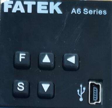
The Panel Operator consists of a panel display and Panel Operator keys.
You can use the Panel Operator to set parameters, display status, execute utility functions, and monitor servo driver operation. The Panel Operator key names and functions are given below.
|
Key |
Key |
Function |
|
Function Key |
Changes the display. Status Display, Assistance Tool、Parameter Setup, Monitering. |
|
|
Setting Key |
Pressing this key displays the setup and setup values of each parameter, enters the parameter setup state, and clears error alarm. |
|
|
UPKey |
Increases the setting. In the assistance tool mode, the JOG operation acts as a forward start key |
|
|
Down Key |
Decreases the setting. In the assistance tool mode, the JOG operation acts as a reverse start key |
|
|
Shift Key |
Moves to the next digit on the left when a digit is flashing. |
8.1.2 Changing Modes
Press the F Key to change between the modes as shown below.
Refer to the reference pages for the operating procedures in each function mode.
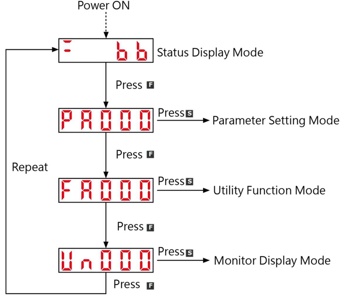
NOTE: You can change the setting of Pn52F (Monitor Display at Startup) to display the Monitor Display Mode instead of the Status Display Mode after the power supply is turned ON.Set Pn52F to the Un number of the monitor display to display after the power supply is turned ON.
|
Pn52F |
|
|||||||
|
Setup Range |
Setup Unit |
default setting |
When Enabled |
Classification |
||||
|
0000 ~ 0FFF |
– |
0FFF |
immediately |
Setup |
||||
If 0FFF is set (default setting), the servo driver will enter the Status Display Mode after the power supply is turned ON.
8.1.3 Status Displays
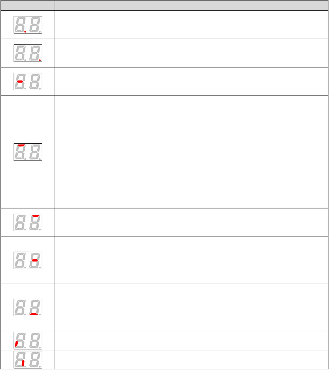
The status is displayed as described below.
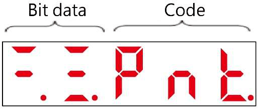
■ Interpreting Bit Data
Display Meaning
Control Power ON Display
Lit while the servo driver control power is ON.
Not lit if the servo driver control power is OFF.
Main Power ON Display
Lit while the servo driver Main power is ON.
Not lit if the servo driver Main power is OFF.
Base Block Display
Lit if the servo is OFF.
Not lit while the servo is ON.
During Speed Control: /V-CMP (Speed Coincidence Detection) Signal Display
Lit if the difference between the Servomotor speed and the reference speed is the same as or less than the setting of Pn503 or Pn582. (The default setting is 10 min-1 or 10 mm/s.) Always lit during torque control.
Additional Information
If there is noise in the reference voltage during speed control, the horizontal segment (-) on the top of the leftmost digit on the Panel Operator display may flash. Refer to the following section and implement countermeasures against noise.
During Position Control: /COIN (Positioning Completion) Signal Display
Lit if the deviation between the position reference and actual motor position is equal to or less than the setting of Pn522. (The default setting is 7 reference units.) Not lit it the deviation exceeds the setting.
/TGON (Rotation Detection) Signal Display
Lit if the Servomotor speed is higher than the setting of Pn502 or Pn581 and not lit if the speed is lower than the setting. (The default setting is 20 min-1 or 20 mm/s.)
During Speed Control: Speed Reference Input Display
Lit if the current input reference is larger than the setting of Pn502 or Pn581 and not lit if the reference is smaller than the setting. (The default setting is 20 min-1 or 20 mm/s.)
During Position Control: Reference Pulse Input Display
Lit while reference pulses are being input. Not lit if reference pulses are not being input.
“During Torque Control: Torque Reference Input Display
Lit if the current input torque reference is larger than the specified value (10% of the rated torque) and not lit if the reference is smaller than the specified value.
During Position Control: Clear Signal Input Display
Lit while the clear signal is being input. Not lit if the clear signal is not being input.
EtherCAT (Input) Connert Display
The Status.of CN3
EtherECAT (Output) Connert Display
The Status.of CN4
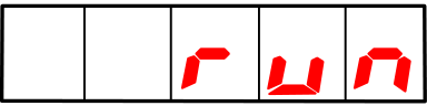
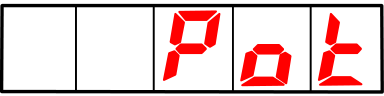
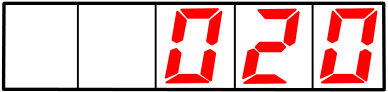
■ Interpreting Codes
|
Display |
Meaning |
|
|
Base Block Active |
|
|
Operation in Progress |
|
|
Forward Drive Prohibited |

|
Display |
Meaning |
|
|
Reverse Drive Prohibited |
|
|
Forward Drive Prohibited and Reverse DriveProhibited |
|
|
Forced Stop Status |
|
|
Test without Motor in Progress |
|
|
Alarm Status |




8.2 Parameter (Pn ▯▯▯) Operations on the Panel Operator
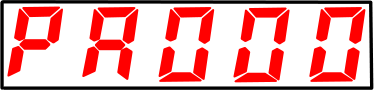
The Panel Operator displays numbers beginning with “Pn.”
NOTE: The SC3 servo driver currently supports only single-axis motors, so PA represents the parameters for the first axis. If dual-axis motors are supported in the future, PB will represent the parameters for the second axis.
This section describes the procedures for setting the parameters that are used in this manual.
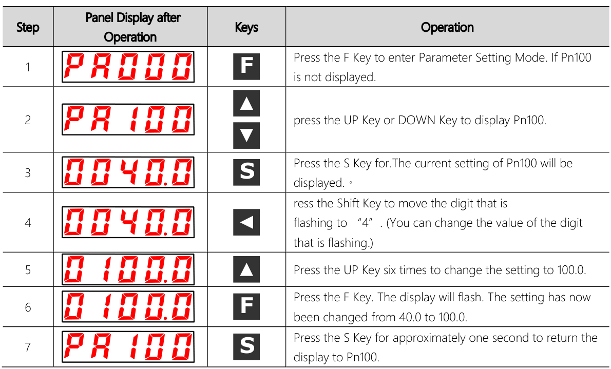
8.2.1 “Setting Parameters That Require Numeric Settings
The following procedure shows how to change the setting of Pn100 (Speed Loop Gain) from 40.0 to 100.0 as an example of a parameter that requires a numeric setting.
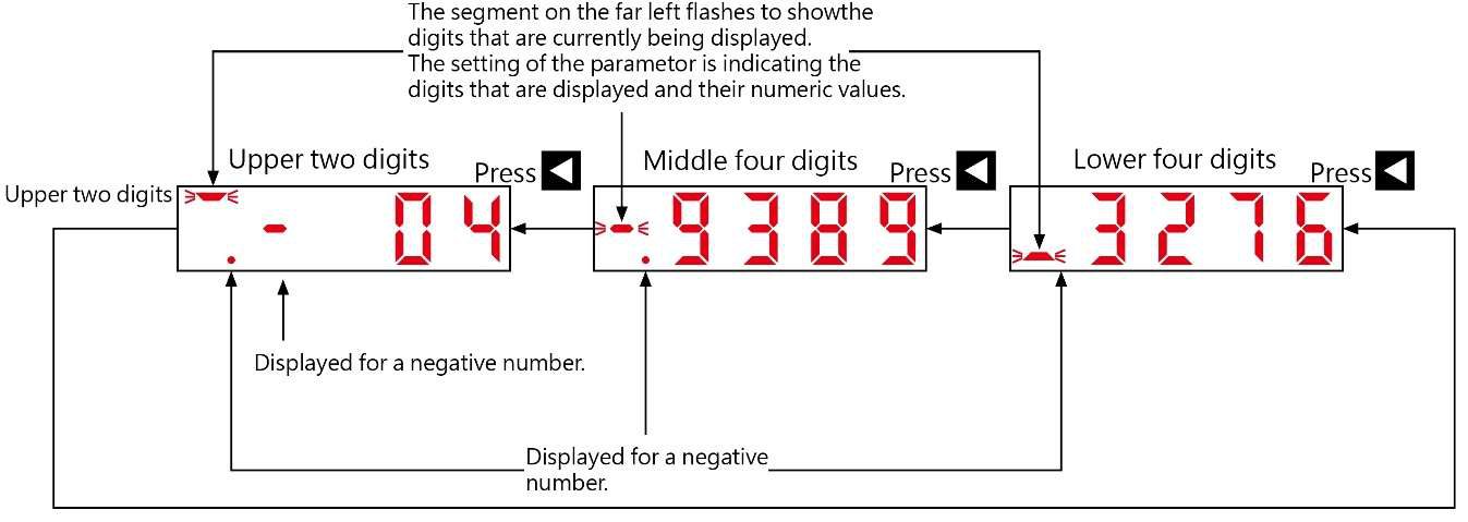
◆ Parameters with Settings of More Than Five Digits
The Panel Operator displays five digits. Settings of more than five digits are displayed as shown in the following figure.


8.2.2 “Setting Parameters That Require Selection of Functions
For parameters that require selection of functions, you can select the individual digits of the numbers displayed on the Panel Operator to set the functions assigned to them.
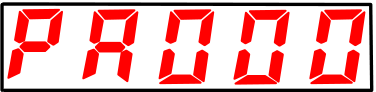
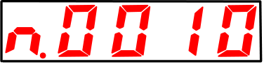
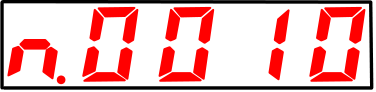
The following example shows how to change the setting of Pn000 = n.▯▯X ▯ (Control Method Selection) in Pn000 (Basic Function Selections 0) from speed control to position control.
|
Step |
Panel Display after Operation |
Keys |
Operation |
|
1 |
|
F |
Press the F Key to enter Parameter Setting Mode. If Pn000 is not displayed, press the UP Key or DOWN Key to display Pn000. |
|
3 |
|
S |
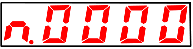
Press the S Key. for approximately one second. The current setting of Pn000 will be displayed. |
|
4 |
|
|
Press the S Key. to move the digit that is flashing. (You can change the value of the digit that is flashing.) |
|
5 |
|
|
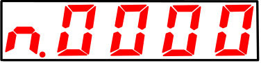
Press the UP Key once to change the display to n.0010. (This changes the control method from speed control to position control.) |
|
6 |
|
F |
Press the F Key. The display will flash. The control method has now been changed from speed control to position control. |
|
7 |
|
S |
Press the S Key. for approximately one second. Pn000 is displayed again. |




8.3 Monitor Display (Un ▯▯▯) Operations on the Panel Operator
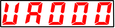
You can monitor the status of the reference values and I/O signals that are set in the servo driver and the internal status of the servo driver with monitor displays. The Panel Operator displays numbers beginning with “Un.”
NOTE: The SC3 servo driver currently supports only single-axis motors, so UA represents the parameters for the first axis. If dual-axis motors are supported in the future, UB will represent the parameters for the second axis.
Display Example for Motor Speed
This section describes the basic operations for monitor displays and how to interpret some special monitor displays. ■ List of Monitor Display
|
Monitor |
Meaning |
Unit |
|
Un000 |
Motor Speed |
1r/min |
|
Un001 |
Speed Refence |
1r/min |
|
Un002 |
Torque Refence |
1% |
|
Un003 |
Rotation Angle 1 |
encoder pulse |
|
Un004 |
Rotation Angle 2 |
deg |
|
Un005 |
Input Signal Monitor |
|
|
Un006 |
Output Signal Monitor |
|
|
Un007 |
Input Speed Command |
1r/min |
|
Un008 |
Position Deviatoin |
command |
|
Un009 |
Cumulative Load Rate |
1% |
|
Un00A |
Re-generative Load Rate |
1% |
|
Un00B |
DB Resistor Power Consumption |
1% |
|
Un00C |
Input Command Counter |
command |
|
Un00D |
Feedback Pulse Counter |
encoder pulse |
|
Un013 |
Feedback Pulse Counter |
command |
|
Un020 |
Rated Speed of Motor |
1r/min |
|
Un021 |
MAX. Speed of Motor |
1r/min |
|
Un040 |
The Number of Rotation of Absulte Encoder |
r |
|
Un041 |
The Position of One Rotation of Absulte Encoder |
encoder pulse |
|
Un140 |
Bus Voltage |
1V |
8.3.1 Basic Monitor Display Operations
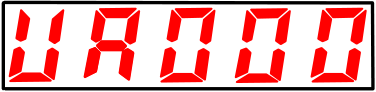
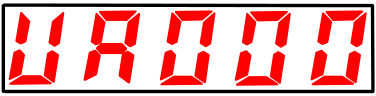
The procedure for Un000 (Motor Speed) is described here as an example.
|
Step |
Panel Display after Operation |
Keys |
Operation |
||
|
1 |
|
F |
Press the F Key to enter Monitor Display Mode. |
||
|
2 |
|
S |
Press the S Key.The contents of the monitor display for the specified Un number will appear. |
||
|
3 |
|
|
— |
||
|
3 |
|
S |
Press the S Key for approximately one second. The display shown for step 1 will appear again. |




8.3.2 Input Signal Monitor (Un005/Un006)
You can use Un005/Un006 to display the status of allocated signals on the LED segments of the Panel Operator.
◆ Interpreting the Display
LED Segments
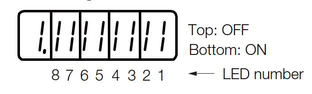
• If the input signal that corresponds to the LED number is OFF, the top LED segment will be lit. • If the input signal that corresponds to the LED number is ON, the bottom LED segment will be lit. The allocations are given in the following table.
|
Monitor Number |
LED number |
Input Pin Number |
|
Un005 |
0 |
IN0(CN1-14) |
|
1 |
IN1(CN1-15) |
|
|
2 |
IN2(CN1-16) |
|
|
3 |
IN3(CN1-17) |
|
|
4 |
IN4(CN1-39) |
|
|
5 |
IN5(CN1-40) |
|
|
6 |
IN6(CN1-41) |
|
|
7 |
IN7(CN1-42) |
|
|
Un006 |
0 |
OUT0(CN1-7,-8) |
|
1 |
OUT1(CN1-9,-10) |
|
|
2 |
OUT2(CN1-11,-12) |
|
|
3 |
OUT3(CN1-32,-33) |
|
|
4 |
OUT4(CN1-34,-35) |
|
|
5 |
OUT5(CN1-36,-37) |
8.4 Utility Function (FA ▯▯▯) Operations on the Panel Operator
Utility functions are used to set up and tune the servo driver.
The Panel Operator displays numbers beginning with “FA.”
NOTE: The SC3 servo driver currently supports only single-axis motors, so FA represents the parameters for the first axis. If dual-axis motors are supported in the future, FB will represent the parameters for the second axis.
Display Example: Origin Search

The operating procedures from the Panel Operator are described here. Refer to the descriptions of individual utility functions for preparations and related parameters.
■ List of Assistance Tool
|
Utility Function Number |
Function |
|
FA000 |
Display Alarm History |
|
FA002 |
Jog |
|
FA003 |
Origin Search |
|
FA004 |
Jog Program |
|
FA005 |
Initialize Parameters |
|
FA006 |
Clear Alarm History |
|
FA008 |
Reset Absolute Encoder |
|
FA009 |
Autotune Analog (Speed/Torque) Reference Offset |
|
FA00A |
Manually Adjust Speed Reference Offset |
|
FA00B |
Manually Adjust Torque Reference Offset |
|
FA00E |
Autotune Motor Current Detection Signal Offset |
|
FA010 |
Write Prohibition Setting |
|
FA011 |
Display Servomotor Model |
|
FA012 |
Display Software Version |
|
FA203 |
One-Parameter Tuning |
|
FA206 |
Easy FFT |
|
FA208 |
Load Inertia Detection |
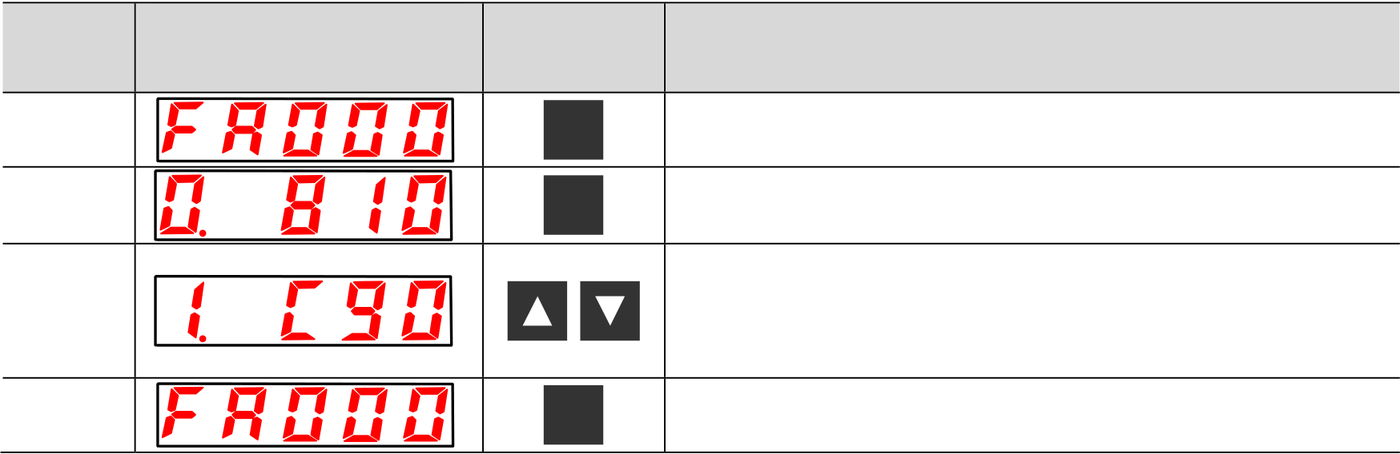
8.4.1 Display Alarm History(FA000)
Refer to the following section for information on this utility function other than the procedure.
|
Step |
Panel Display after |
Keys |
Operation |
|
Operation |
|||
|
1 |
F |
Press the F Key to enter Utility Function Mode. |
|
|
2 |
S |
Press the S Key.The most recent alarm will be displayed. |
Press the DOWN Key to display the next older alarm.
3 Press the UP Key to display the next newer alarm. The higher the far-left segment is, the older the alarm is.
|
4 |
S |
Press the S Key again to return the display to FA000. |
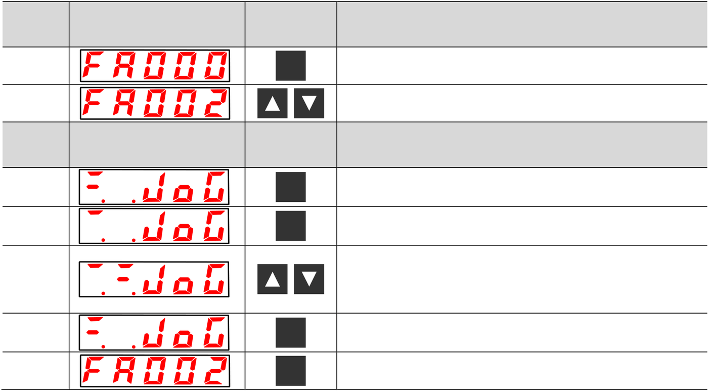
8.4.2 JOG(FA002)
Refer to the following section for information on this utility function other than the procedure.
|
Step |
Panel Display after |
Keys |
Operation |
|
Operation |
|||
|
1 |
Panel Display after |
F |
Press the F Key to enter Utility Function Mode. |
|
2 |
Press the UP Key or DOWN Key to display FA02. |
||
|
Step |
Keys |
Operation |
|
|
Operation |
|||
|
3 |
S |
Press the S Key. The display shown at the left will appear. |
|
|
4 |
F |
Press the F Key to turn ON the servo. |
The Servomotor will operate at the speed set in Pn304 or 5 Pn383 while the UP Key (for forward operation) or DOWN Key (for reverse operation) is pressed.
|
6 |
F |
Press the F Key to turn OFF the servo. |
|
7 |
S |
Press the S Key again to return the display to FA002. |
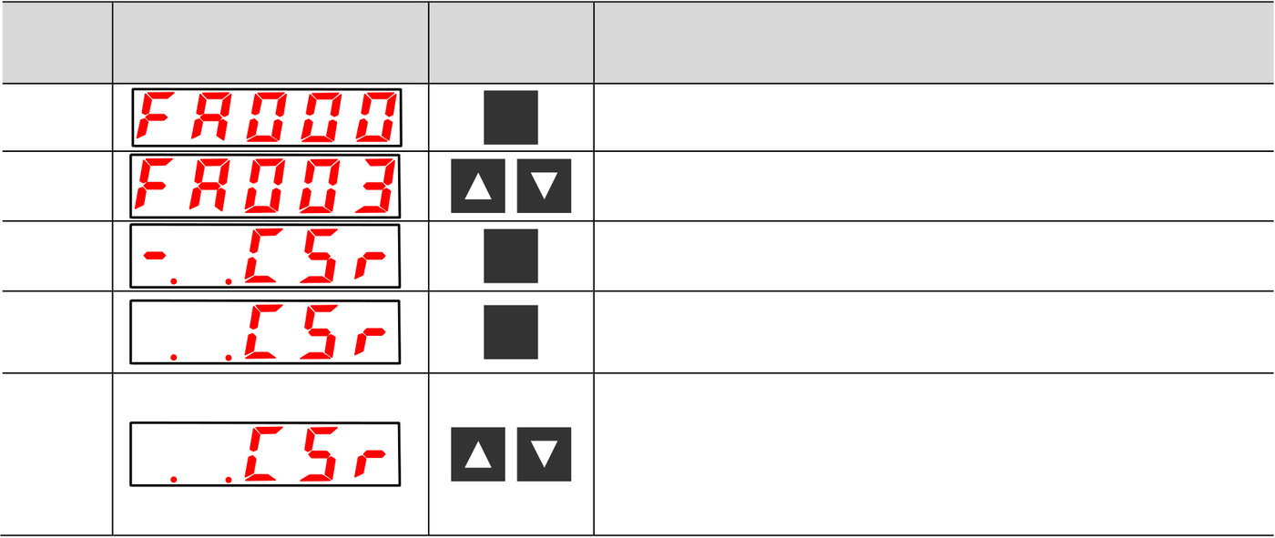
8.4.3 Origin Search(FA003)
Refer to the following section for information on this utility function other than the procedure.
|
Step |
Panel Display after |
Keys |
Operation |
|
Operation |
|||
|
1 |
F |
Press the F Key to enter Utility Function Mode. |
|
|
2 |
S |
Press the UP Key or DOWN Key to display FA003. |
|
|
3 |
Press the S Key The display shown at the left will appear. |
||
|
4 |
F |
Press the F Key to turn ON the servo. |
|
|
Additional Information |
Press the UP Key to operate the Servomotor in the forward
|
5 |
direction. Press the DOWN Key to operate the Servomotor in the |
reverse direction.

|
6 |
F |
When the Servomotor origin search has been completed, the |
|
display will flash. At this time, the Servomotor is servo-locked |
at the origin within one rotation of the encoder.
|
7 |
S |
Press the S Key again to return the display to FA003. |
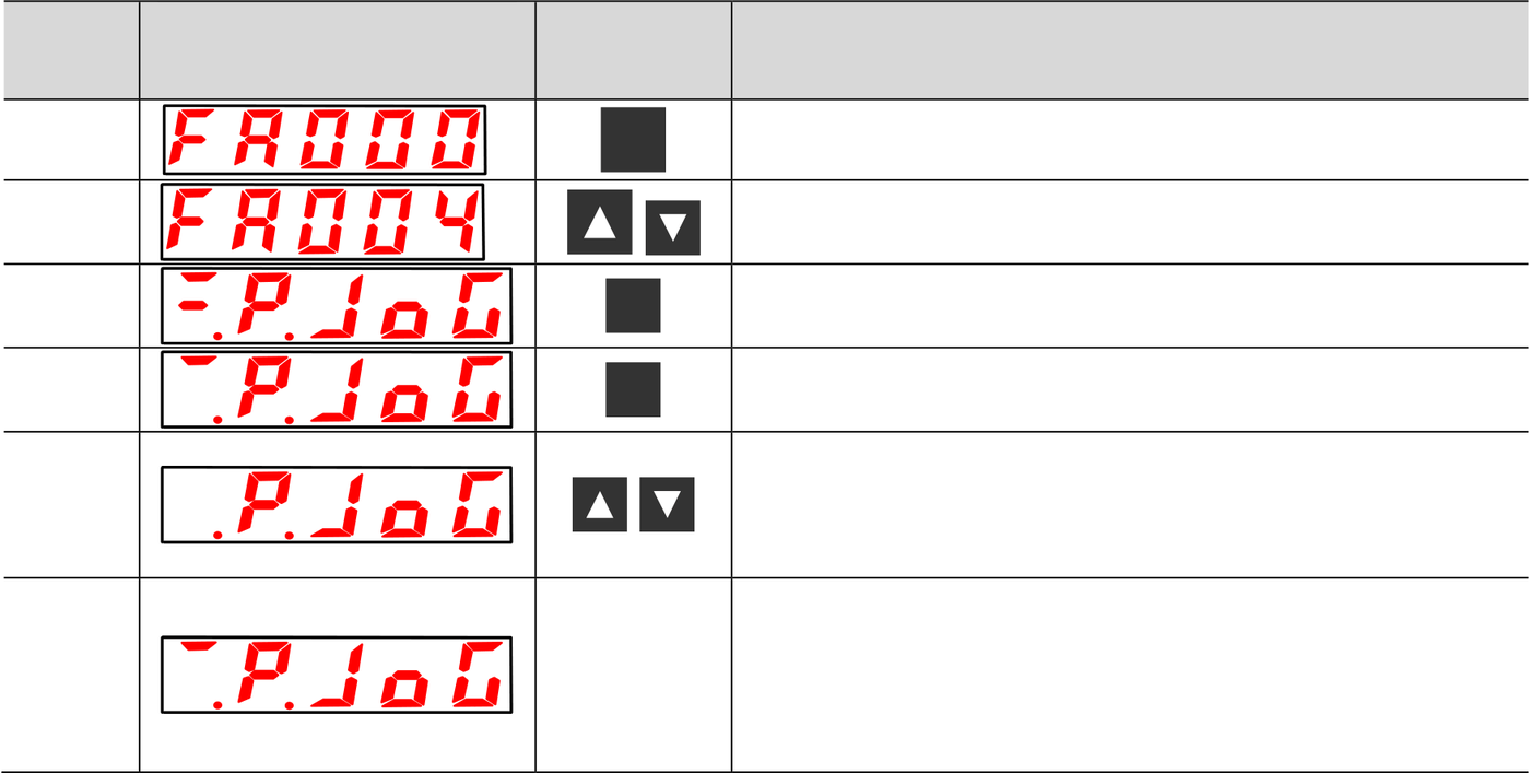
8.4.4 Jog Program(FA004)
Refer to the following section for information on this utility function other than the procedure.
|
Step |
Panel Display after |
Keys |
Operation |
|
Operation |
|||
|
1 |
F |
Press the F Key to enter Utility Function Mode. |
|
|
2 |
S |
Press the UP Key or DOWN Key to display FA004. |
|
|
3 |
Press the S Key. The display shown at the left will appear. |
||
|
4 |
Press the F Key to turn ON the servo. |
||
|
F |
Press the UP Key or DOWN Key according to the initial
5 movement direction of the operation pattern. The operation
will start after the preset waiting time.
When program jogging has been completed, End will flash
|
6 |
– |
on the display, and then the display shown on the left will |
|
appear again. |
Press the S Key again to return the step 2.
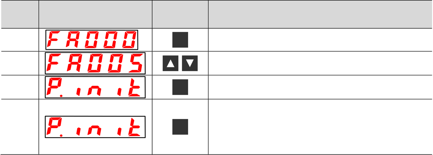
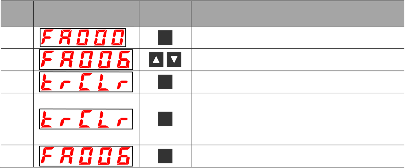
8.4.5 Initialize Parameters(FA005)
Refer to the following section for information on this utility function other than the procedure.
|
Step |
Panel Display after |
Keys |
Operation |
|
Operation |
|||
|
1 |
F |
Press the F Key to enter Utility Function Mode. |
|
|
2 |
S |
Press the UP Key or DOWN Key to display FA005. |
|
|
3 |
Press the S Key. The display shown at the left will appear. |
Press the F Key to initialize the parameters.
|
4 |
F |
When the initialization has been completed, donE will flash |
|
on the display, and then the display shown on the left will |
appear again.
8.4.6 Clear Alarm History(FA006)
Refer to the following section for information on this utility function other than the procedure.
|
Step |
Panel Display after |
Keys |
Operation |
|
Operation |
|||
|
1 |
F |
Press the F Key to enter Utility Function Mode. |
|
|
2 |
Press the UP Key or DOWN Key to display FA006. |
||
|
S |
|||
|
3 |
Press the S Key. The display shown at the left will appear. |
Press the F Key to clear the alarm history.
|
4 |
F |
When deleting the alarms has been completed, donE will |
|
flash on the display, and then the display shown on the left |
will appear again.
|
5 |
S |
Press the S Key again to return the display to FA006. |
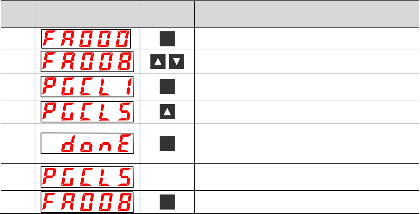
8.4.7 Reset Absolute Encoder(FA008)
Refer to the following section for information on this utility function other than the procedure.
|
Step |
Panel Display after |
Keys |
Operation |
|
Operation |
|||
|
1 |
F |
Press the F Key to enter Utility Function Mode. |
|
|
2 |
Press the UP Key or DOWN Key to display FA008. |
||
|
S |
|||
|
Press the S Key. |
|||
|
3 |
|||
|
PGCL1 will be displayed. |
|||
|
4 |
F |
Continue pressing the UP Key until PGCL5 is displayed. |
|
|
Press the F Key.The absolute encoder will be initialized. |
|||
|
5 |
When initialization has been completed, donE will flash on |
the display for approximately one second.
|
6 |
– |
After displaying donE, the display will return to the PGCL5 |
|
display. |
||
|
7 |
S |
Press the S Key again to return the display to FA008. |
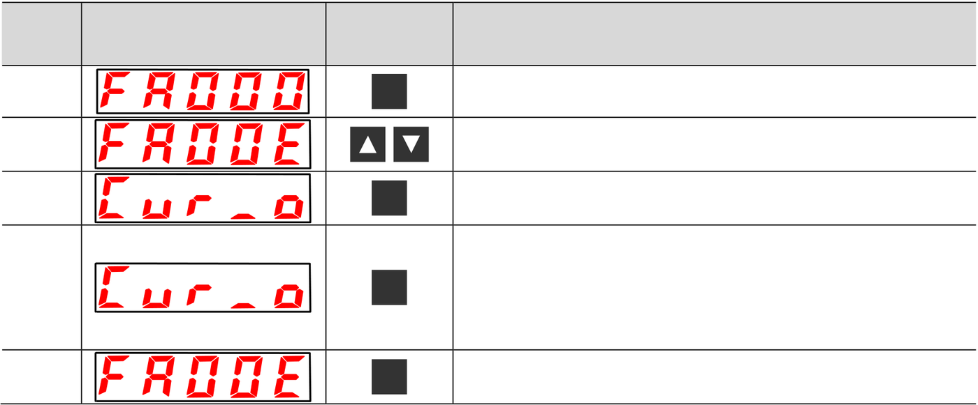
8.4.8 Autotune Motor Current Detection Signal Offset(FA00E)
Refer to the following section for information on this utility function other than the procedure.
|
Step |
Panel Display after |
Keys |
Operation |
|
Operation |
|||
|
1 |
F |
Press the F Key to enter Utility Function Mode. |
|
|
2 |
Press the UP Key or DOWN Key to display FA00E. |
||
|
S |
|||
|
3 |
Press the S Key. The display shown at the left will appear. |
Press the F Key to perform automatic offset-signal
|
4 |
F |
adjustment. When the adjustment has been completed, donE |
|
will flash on the display, and then the display shown on the |
left will appear again.
|
5 |
S |
Press the S Key again to return the display to FA00E. |
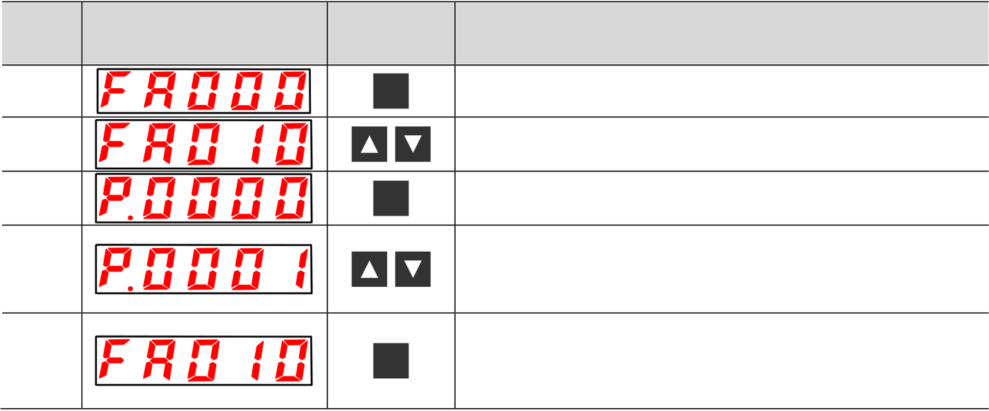
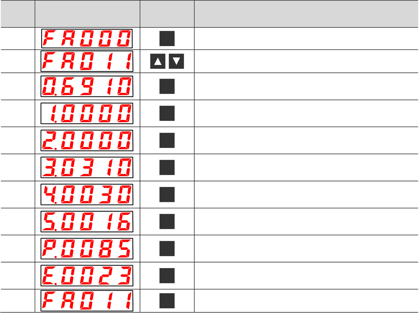
8.4.9 Write Prohibition Setting(FA010)
Refer to the following section for information on this utility function other than the procedure.
|
Step |
Panel Display after |
Keys |
Operation |
|
Operation |
|||
|
1 |
F |
Press the F Key to enter Utility Function Mode. |
|
|
2 |
Press the UP Key or DOWN Key to display FA010 |
||
|
S |
|||
|
3 |
Press the S Key. The display shown at the left will appear. |
||
|
4 |
F |
Press the UP Key or DOWN Key and set one of the following. |
|
|
P.0000: Write permitted (default setting) |
|||
|
P.0001: Write prohibited |
|||
|
Press the F Key to enter the value. When the setting has been |
|||
|
5 |
completed, donE will flash on the display, and then the display |
||
|
shown on the left will appear again. |
8.4.10 Display Servomotor Model(FA011)
Refer to the following section for information on this utility function other than the procedure.
|
Step |
Panel Display after |
Keys |
Operation |
|
Operation |
|||
|
1 |
F |
Press the F Key to enter Utility Function Mode. |
|
|
2 |
S |
Press the UP Key or DOWN Key to display FA011 |
|
|
Press the S Key to display the Servomotor voltage and model |
|||
|
3 |
|||
|
codes. |
|||
|
4 |
F |
Press the F Key. |
|
|
The Servomotor Parameter 1 will be displayed. |
|||
|
5 |
F |
Press the F Key. |
|
|
The Servomotor Parameter 2 will be displayed. |
|||
|
6 |
F |
Press the F Key. |
|
|
The Servomotor Parameter 3 will be displayed. |
|||
|
7 |
F |
Press the F Key. |
|
|
The Servomotor Parameter 4 will be displayed. |
|||
|
8 |
F |
Press the F Key. |
|
|
The Servomotor Parameter 5 will be displayed. |
|||
|
9 |
F |
Press the F Key. |
|
|
The Servomotor capacity will be displayed. |
|||
|
10 |
F |
Press the F Key. |
|
|
The Encoder Resolution will be displayed. |
|||
|
11 |
S |
Press the S Key again to return the display to FA011. |
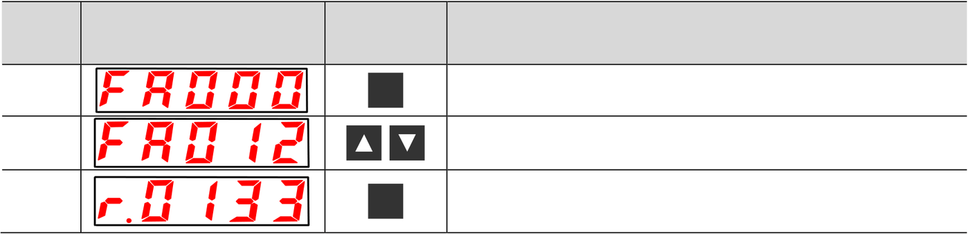
8.4.11 Display Software Version(FA012)
Refer to the following section for information on this utility function other than the procedure.
|
Step |
Panel Display after |
Keys |
Operation |
|
Operation |
|||
|
1 |
F |
Press the F Key to enter Utility Function Mode. |
|
|
2 |
Press the UP Key or DOWN Key to display FA012 |
||
|
S |
|||
|
Press the S Key. |
|||
|
3 |
|||
|
The software version of the servo driver will be displayed. |

|
4 |
F |
Press the F Key. |
|
The FPGA version will be displayed. |
||
|
5 |
S |
Press the S Key again to return the display to FA012. |
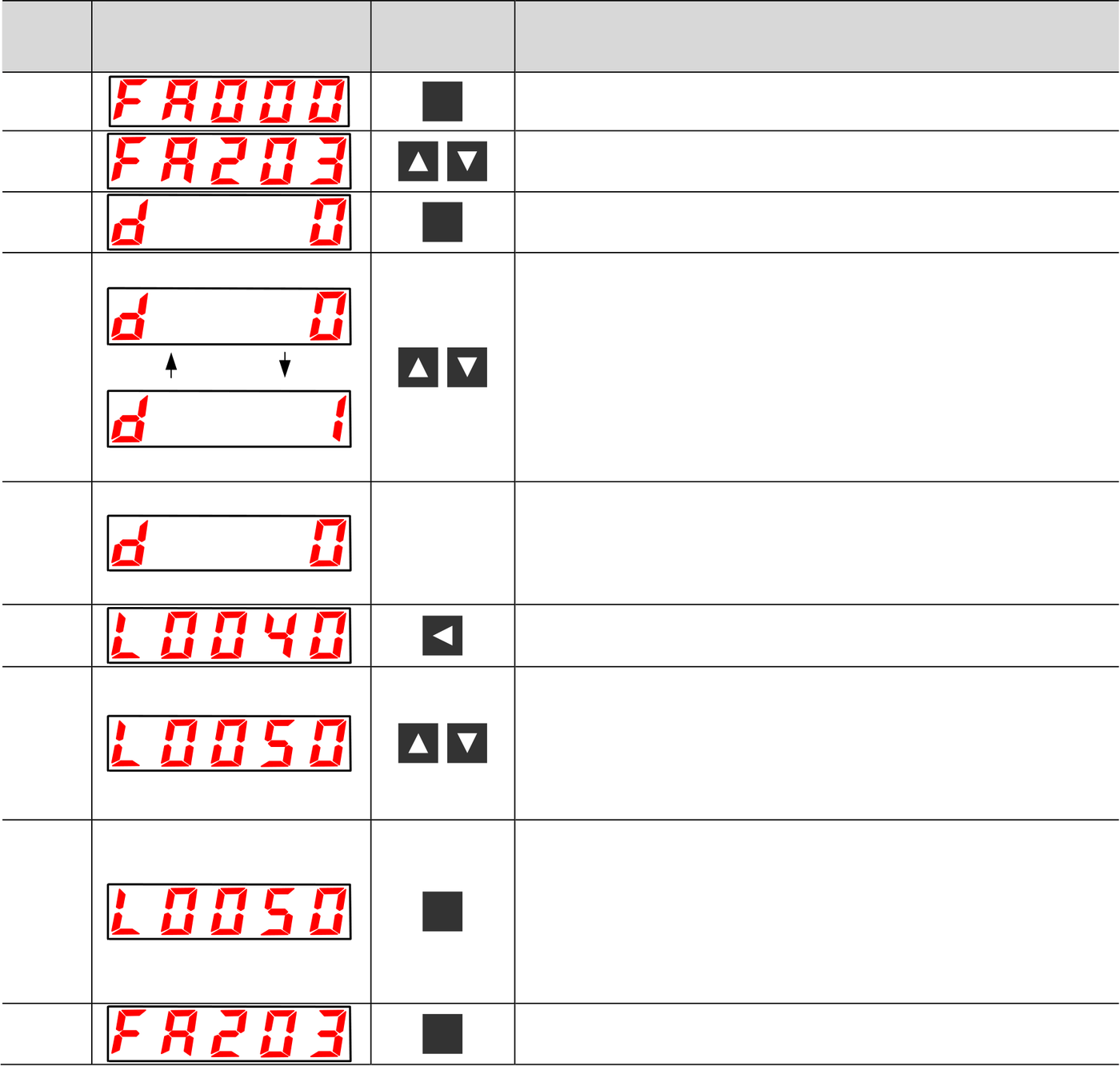
8.4.12 One-Parameter Tuning(FA203)
Refer to the following section for information on this utility function other than the procedure.
|
Step |
Panel Display after |
Keys |
Operation |
|
Operation |
|||
|
1 |
F |
Press the F Key to enter Utility Function Mode. |
|
|
2 |
S |
Press the UP Key or DOWN Key to display FA20 |
|
|
3 |
Press the S Key. The display shown at the left will appear. |
Press the UP Key or DOWN Key to enter Tuning Mode.
Tuning Mode (Strength of Tuning Setting)
4 0: Performs tuning giving priority to stability.
1: Performs tuning giving priority to response.
NOTE: The rigidity type is always 2.
If the servo is OFF (i.e., if power is not supplied to the
|
5 |
– |
Servomotor), input the /S-ON (Servo ON) from the host |
|
controller. |
If the servo is ON, go to step 6.
|
6 |
Press the S Key. The one-parameter gain will be displayed as shown on the left. |
Press the UP Key or DOWN Key to change the oneparameter gain value and change the actual servo gains (Pn100, Pn101, 7 Pn102, and Pn401) at the same time.
You end this tuning function when you decide that the
response is satisfactory.
Press the F Key to save the four calculated gains to the
parameters. When tuning has been completed, donE will flash
|
8 |
F |
on the display, and then the display shown on the left will |
|
appear again. |
NOTE: To end operation without saving the calculated gains,
go to step 9.
|
9 |
S |
Press the S Key again to return the display to FA203. |
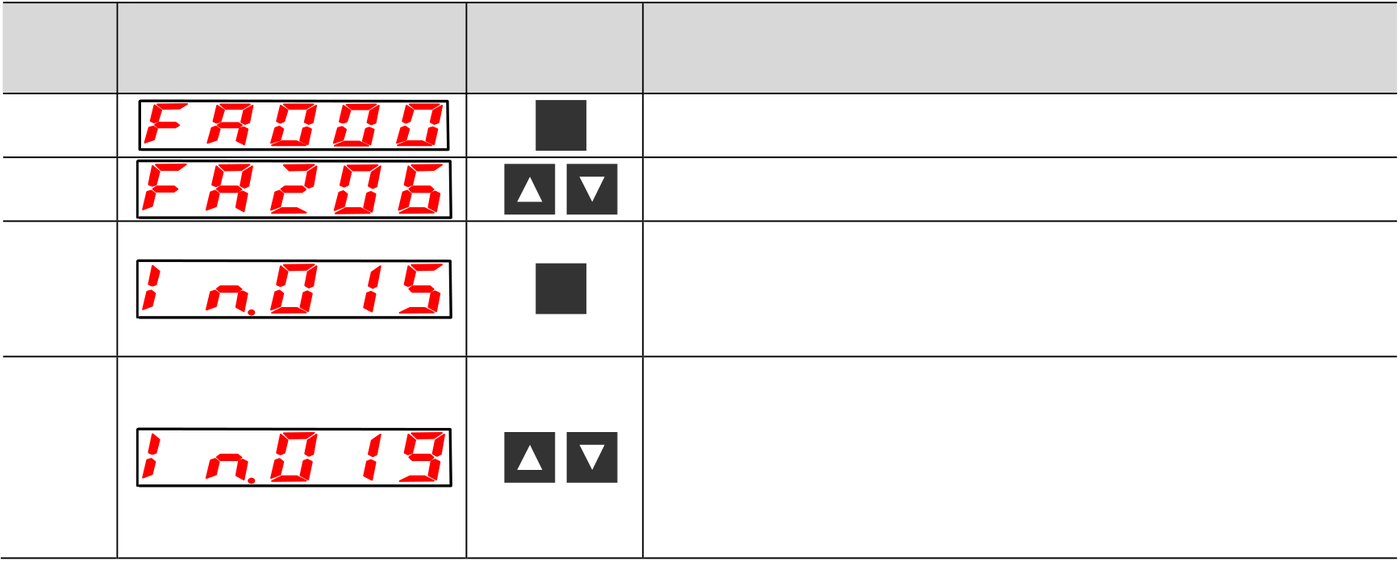
8.4.13 EasyFFT(FA206)
Refer to the following section for information on this utility function other than the procedure.
|
Step |
Panel Display after |
Keys |
Operation |
|
Operation |
|||
|
1 |
F |
Press the F Key to enter Utility Function Mode. |
|
|
2 |
Press the UP Key or DOWN Key to display FA206 |
||
|
S |
|||
|
Press the S Key. |
|||
|
3 |
The display shown on the left will appear and the Panel |
Operator will enter Reference Amplitude Setting Mode.
|
4 |
Press the UP Key or DOWN Key to set the reference amplitude. Reference amplitude setting range: 1 to 800 NOTE: 1. If you are setting Easy FFT for the first time, do not change the reference amplitude setting, but rather start from the default value of 15. Although |


|
increasing the reference amplitude will increase the detection accuracy, the vibration and noise in the machine will increase momentarily. Increase the reference amplitude a little at a time and observe the results. 2. The set reference amplitude will be stored in Pn456. |
|||
|
5 |
|
S |
Press the S Key. The ready to operate status will be entered. |
|
6 |
|
F |
Press the F Key to turn ON the servo. Additional Information |
|
7 |
|
|
While the servo is ON, press the UP Key (forward) or the DOWN Key (reverse). The Servomotor will automatically perform round-trip operation, moving in forward and reverse several times for 1/4th of a rotation NOTE: 1. Press the F Key to cancel the operation. Return to step 5. 2. The Servomotor will move slightly. Also at the same time, the Servomotor will emit noise. To ensure safety, do not approach or enter the range of machine motion. |
|
|
— |
If detection is completed normally, E_FFt will stop flashing and the detected resonance frequency will be displayed. If To check the results, go to step 9. To monitor the resonance frequency without setting the detection result, press the S Key to return to step 2. ● IMPORTANT If the operation ended normally but it took two seconds or longer, the detection accuracy may not be sufficient. Increase the reference amplitude to a value higher than 15 to increase the detection accuracy. Although increasing the reference amplitude will increase the detection accuracy, the vibration and noise in the machine will increase momentarily. Increase the reference amplitude a little at a time and observe the results. |
|
|
9 |
|
F |
Press the F Key. The optimum notch filter for the detected resonance frequency will automatically be set. If the notch filter is set correctly, donE will flash on the display, and then the display shown on the left will appear. If the 1st notch filter frequency is already set (Pn408 = n.▯▯▯1), the 2nd notch filter frequency will be automatically set (Pn40C). Press the F Key to return to step 5. NOTE: 1. If both the 1st and 2nd notch filter frequencies are already set (Pn408 = n.▯1 ▯1), no more notch filter frequencies can be set. 2. If the frequency detected by this function is not to be used, set Pn408 to n.▯▯▯0 (Disable notch filter). |
|
10 |
|
S |
Press the S Key again to return the display to FA206. |








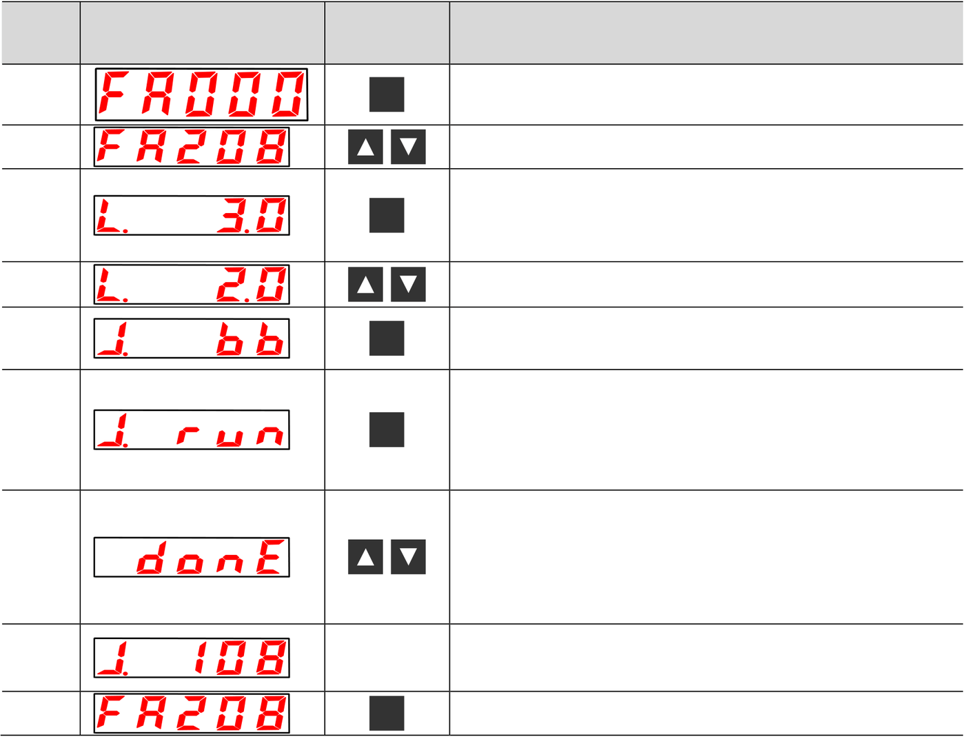
8.4.17 Load Inertia Detection (FA208)
Refer to the following section for information on this utility function other than the procedure.
|
Step |
Panel Display after |
Keys |
Operation |
|
Operation |
|||
|
1 |
F |
Press the F Key to enter Utility Function Mode. |
|
|
2 |
Press the UP Key or DOWN Key to display FA208 |
||
|
S |
|||
|
Press the S key to display the content as shown in the left |
|||
|
3 |
image, entering the movement distance settings of load |
inertia detection.
|
4 |
S |
Press the UP or DOWN key to set the movement distance |
|
5 |
Press the S Key. |
|
|
The ready to operate status will be entered. |
Press the F Key to turn ON the servo.
|
6 |
S |
Additional Information |
|
Press the F Key again to turn OFF the servo. |
Return to step 5.
|
7 |
— |
In the servo ON state, pressing the UP (forward) or DOWN |
|
(reverse) key will cause the servo motor to repeatedly rotate |
||
|
forward and backward within the setup movement distance a |
||
|
few times. The execution time is approximately 8 seconds. |
||
|
8 |
During the operation, the display shown in the left image will |
|
|
flash. |
||
|
After the detection process concludes successfully, the |
||
|
flashing will stop, and the detected load inertia percentage |
||
|
will be displayed. If the detection fails, "J.—-" will be shown. |
||
|
9 |
S |
|
|
Press the S Key again to return the display to FA208. |
Tip: press ← → to switch chapters, Ctrl+K to search