12.1 Overview and Flow of Tuning
Tuning is performed to optimize response by adjusting the servo gains in the servo driver.
The servo gains are set using a combination of parameters, such as parameters for the speed loop gain, position loop gain, filters, friction compensation, and moment of inertia ratio. These parameters influence each other, so you must consider the balance between them.
The servo gains are set to stable settings by default. Use the various tuning functions to increase the response even further for the conditions of your machine.
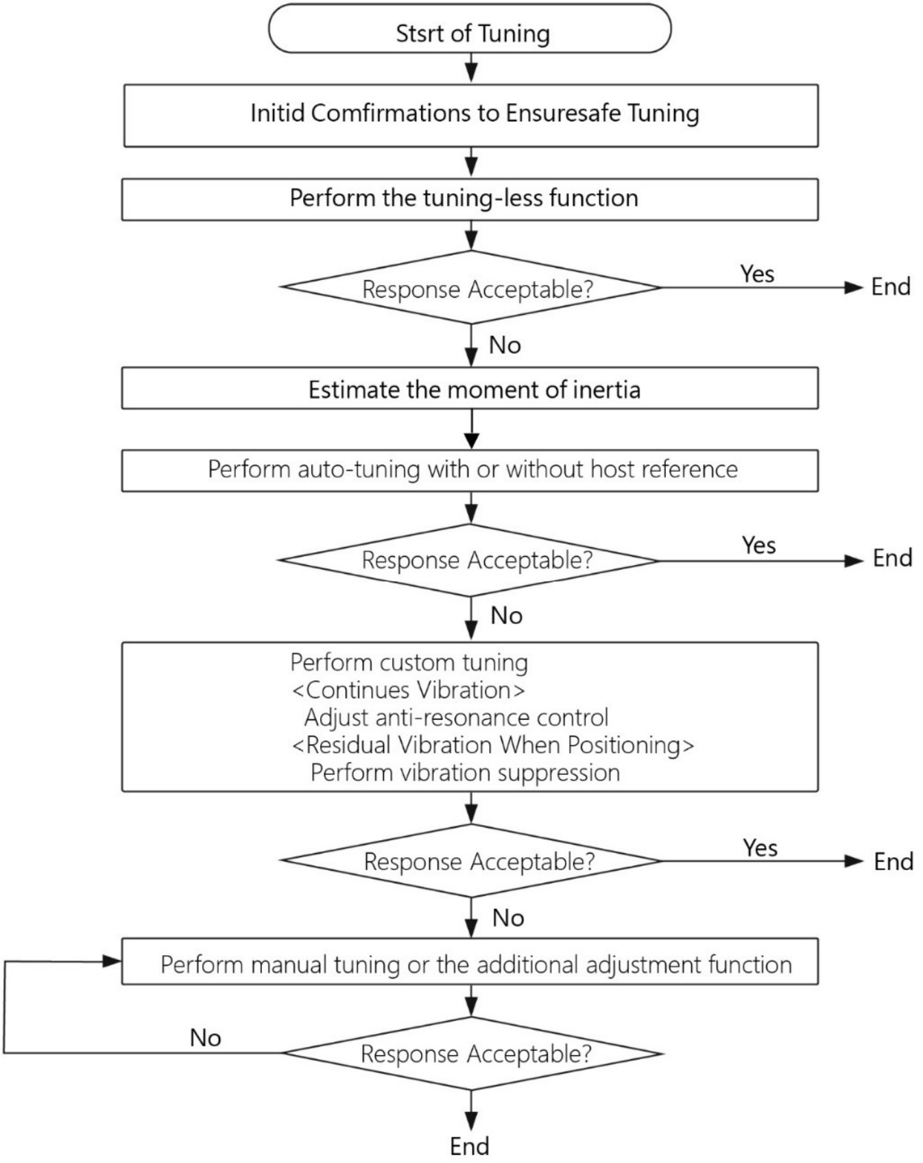
The basic tuning procedure is shown in the following flowchart. Make suitable adjustments considering the conditions and operating requirements of your machine.
12.1.1 Tuning Functions
The following table provides an overview of the tuning functions.
|
Tuning Function |
Outline |
Applicable Con trol Methods |
Reference |
|
Tuning-less Function |
This automatic adjustment function is designed to enable stable operation without servo tuning. This function can be used to obtain a stable response regardless of the type of machine or changes in the load. You can use it with the default settings. |
Speed control or position control |
Page 12-10 |
|
Moment of Inertia Estimation |
The moment of inertia ratio is calculated by operat-ing the Servomotor a few times. The moment of inertia ratio that is calculated here is used in other tuning functions. |
Speed control, |
Page 12-13 |
|
Autotuning without Host Reference |
The following parameters are automatically adjusted in the internal references in the servo driver during automatic operation. •Gains (e.g., position loop gain and speed loop gain) •Filters (torque reference filter and notch filters) |
Speed control or position control |
Page 12-20 |
|
Autotuning with Host Reference |
The following parameters are automatically adjusted with the position reference input from the host controller while the machine is in operation. You can use this function for fine-tuning after you perform autotuning without a host reference. •Gains (e.g., position loop gain and speed loop gain) •Filters (torque reference filter and notch filters) |
Position control |
Page 12-29 |
|
Custom Tuning |
The following parameters are adjusted with the position reference or speed reference input from the host controller while the •Gains (e.g., position loop gain and speed loop gain) •Filters (torque reference filter and notch filters) •Friction compensation |
Speed control or position control |
Page 12-36 |
|
Anti-resonance |
This function effectively suppresses continuous vibration. |
Speed control or position control |
Page 12-44 |
|
Vibration Suppression |
This function effectively suppresses residual vibra-tion if it occurs when positioning. |
Position control |
Page 12-47 |
|
Additional |
This function combines autotuning with custom tuning. You can use it to improve adjustment results. |
Depends on the functions that you use. |
Page 12-51 |
|
Manual Tuning |
You can manually adjust the servo gains to adjust the response. |
Speed control, |
Page 12-58 |
12.1.2 Diagnostic Tool
You can use the following tools to measure the frequency characteristics of the machine and set notch filters.
|
Diagnostic Tool |
Outline |
Applicable Control Methods |
Reference |
|
Easy FFT |
The machine is subjected to vibration to detect resonance frequencies. The measurement results are displayed only as numeric data. |
Speed control, |
Page 12-74 |
12.2 Monitoring Methods
You can use the data tracing function of the ProTuner or the analog monitor signals of the servo driver for monitoring. If you perform custom tuning or manual tuning, always use the above functions to monitor the machine operating status and servo driver signal waveform while you adjust the servo gains.
Check the adjustment results with the following response waveforms.
• Position Control
|
Item |
Unit |
|
|
Rotary Servomotor |
Linear Servomotor |
|
|
Torque reference |
% |
|
|
Feedback speed |
min-1 |
mm/s |
|
Position reference speed |
min-1 |
mm/s |
|
Position deviation |
Reference units |
|
• Speed Control
|
Item |
Unit |
|
|
Rotary Servomotor |
Linear Servomotor |
|
|
Torque reference |
% |
|
|
Feedback speed |
min-1 |
mm/s |
|
Reference speed |
min-1 |
mm/s |
• Torque Control
|
Item |
Unit |
|
|
Rotary Servomotor |
Linear Servomotor |
|
|
Torque reference |
% |
|
|
Feedback speed |
min-1 |
mm/s |


12.3 Precautions to Ensure Safe Tuning
CAUTION
Observe the following precautions when you perform tuning.
• Do not touch the rotating parts of the motor when the servo is ON.
• Before starting the Servomotor, make sure that an emergency stop can be performed at any time. • Make sure that trial operation has been successfully performed without any problems.
• Provide an appropriate stopping device on the machine to ensure safety.
Perform the following settings in a way that is suitable for tuning.
12.3.1 Overtravel Settings
Overtravel settings are made to force the Servomotor to stop for a signal input from a limit switch when a moving part of the machine exceeds the safe movement range.
12.3.2 Torque Limit Settings
You can limit the torque that is output by the Servomotor based on calculations of the torque required for machine operation. You can use torque limits to reduce the amount of shock applied to the machine when problems occur, such as collisions or interference. If the torque limit is lower than the torque that is required for operation, overshooting or vibration may occur.
12.3.3 Setting the Position Deviation Overflow Alarm Level
The position deviation overflow alarm is a protective function that is enabled when the servo driver is used in position control. If the alarm level is set to a suitable value, the servo driver will detect excessive position deviation and will stop the Servomotor if the Servomotor operation does not agree with the refer
ence.
The position deviation is the difference between the position reference value and the actual position.
You can calculate the position deviation from the position loop gain (Pn102) and the motor speed with the following formula.
• Rotary Servomotors

• Linear Servomotors

Position Deviation Overflow Alarm Level (Pn520) [setting unit: reference units]
• Rotary Servomotors

*1. Refer to the following section for details.
*2. When model following control (Pn140 = n.▯▯▯1) is enabled, use the setting of Pn141 (Model Following Control Gain) instead of the setting of Pn102 (Position Loop Gain).
*3. To check the setting of Pn102 on the Digital Operator, change the parameter display setting to display all parameters (Pn00B = n.▯▯▯1).
*4. The underlined coefficient “× (1.2 to 2)” adds a margin to prevent an A.d00 alarm (Position Deviation Overflow) from occurring too frequently.
If you set a value that satisfies the formula, an A.d00 alarm (Position Deviation Overflow) should not occur during normal operation.
If the Servomotor operation does not agree with the reference, position deviation will occur, an error will be detected
, and the Servomotor will stop.
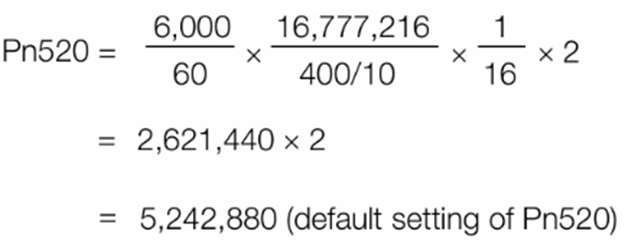
The following calculation example uses a Rotary Servomotor with a maximum motor speed of 6,000 and an encoder resolution of
16,777,216 (24 bits).Pn102 is set to 400.
If the acceleration/deceleration rate required for the position reference exceeds the tracking capacity of the Servomotor, the tracking delay will increase and the position deviation will no longer satisfy the above formulas. If this occurs, lower the acceleration/deceleration rate so that the Servomotor can follow the position reference or increase the position deviation over-flow alarm level.
Related Parameters
|
Pn520 |
Position Deviation Overflow Alarm Level |
Position |
|||||
|
Setting Range |
Setting Unit |
Default Setting |
When Enabled |
Classification |
|||
|
1 ~ 1073741823 |
1 reference unit |
5242880 |
Immediately |
Setup |
|||
Related Alarms
|
Alarm Number |
Alarm Name |
Alarm Meaning |
|
A.d00 |
Position Deviation Overflow |
This alarm is displayed when the position deviation exceeds the set-ting of Pn520 (Position Deviation Overflow Alarm Level). |
12.3.4 Vibration Detection Level Setting
You can set the vibration detection level (Pn312) to more accurately detect A.520 alarms (Vibration Alarm) and A.911 warnings (Vibration)
when vibration is detected during machine operation.
Set the initial vibration detection level to an appropriate value. Refer to the following section for details.
12.3.5 Setting the Position Deviation Overflow Alarm Level at Servo ON
If the servo is turned ON when there is a large position deviation, the Servomotor will attempt to return to the original position to bring the position deviation to 0, which may create a hazardous situation. To prevent this, you can set a position deviation overflow alarm level at servo ON to restrict operation.
The related parameters and alarms are given in the following tables.
Related Parameters
|
Pn526 |
Position Deviation Overflow Alarm Level at Servo ON |
Position |
|||||
|
Setting Range |
Setting Range |
Default Setting |
When Enabled |
Classification |
|||
|
1 ~ 1073741823 |
1 reference unit |
5242880 |
Immediately |
Setup |
|||
|
Pn528 |
Position Deviation Overflow Warning Level at Servo ON |
Position |
|||||
|
Setting Range |
Setting Range |
Default Setting |
When Enabled |
Classification |
|||
|
10 ~ 100 |
1% |
100 |
Immediately |
Setup |
|||
|
Pn529 |
Speed Limit Level at Servo ON |
Position |
|||||
|
Setting Range |
Setting Range |
Default Setting |
When Enabled |
Classification |
|||
|
0 ~ 10000 |
1min-1 |
10000 |
Immediately |
Setup |
|||
Related Alarms
|
Alarm Number |
Alarm Name |
Alarm Meaning |
|
A.d01 |
Position Deviation |
This alarm occurs if the servo is turned ON after the position deviation exceeded the setting of Pn526 (Position Deviation Overflow Alarm Level at Servo ON) while the servo was OFF. |
|
A.d02 |
Position Deviation |
If position deviation remains in the deviation counter, the setting of Pn529 or Pn584 (Speed Limit Level at Servo ON) will limit the speed when the servo is turned ON. This alarm occurs if reference pulses are input and the setting of Pn520 (Position Deviation Overflow Alarm Level) is exceeded. |
Refer to the following section for information on troubleshooting alarms.



12.4 Tuning-less Function
The tuning-less function performs autotuning to obtain a stable response regardless of the type of machine or changes in the load. Autotuning is started when the servo is turned ON.
CAUTION
The tuning-less function is disabled during torque control.
The Servomotor may momentarily emit a sound the first time the servo is turned ON after the Servomotor is connected to the machine. This sound is caused by setting the automatic notch filter. It does not indicate a problem. The sound will not be emitted from the next time the servo is turned ON.
The Servomotor may vibrate if it exceeds the allowable load moment of inertia.
If that occurs, set the tuning-less load level to 2 (Pn170 = n.2 ▯▯▯) or reduce the tuningless rigidity level (Pn170 = n.▯X ▯▯). To ensure safety, make sure that you can perform an emergency stop at any time when you execute the tuning-less function.
12.4.1 Application Restrictions
The following application restrictions apply to the tuning-less function.
|
Function |
Executable * |
Remarks |
|
Vibration Detection Level Initialization |
0 |
− |
|
Moment of Inertia Estimation |
× |
Disable the tuning-less function (Pn170 = n.▯▯▯0) before you execute moment of inertia estimation. |
|
Autotuning without Host Reference |
× |
Disable the tuning-less function (Pn170 = n.▯▯▯0) before you execute autotuning without a host reference. |
|
Autotuning with Host Reference |
× |
− |
|
Custom Tuning |
× |
− |
|
Anti-Resonance Control Adjustment |
× |
− |
|
Vibration Suppression |
× |
− |
|
EasyFFT |
0 |
The tuning-less function is disabled while you execute Easy FFT and then it is enabled when Easy FFT has been completed. |
*0: Yes ×: No
12.4.2 Operating Procedure
The tuning-less function is enabled in the default settings. No specific procedure is required. You can use the following parameter to enable or disable the tuning-less function.
|
Parameter |
Meaning |
When Enabled |
Classification |
|
|
Pn170 |
n.▯▯▯0 |
Disable tuning-less function. |
After restart |
Setup |
|
n.▯▯▯1 |
Enable tuning-less function. |
|||
|
n.▯▯0▯ |
Use for speed control. |
|||
|
n.▯▯1▯ |
Use for speed control and use host controller for position control. |
|||
When you enable the tuning-less function, you can select the tuning-less type. Normally, set Pn14F to n.▯▯2 ▯ (Use tuning-less type 3) (default setting).
If compatibility with previous models is required, set Pn14F to n.▯▯0 ▯ (Use tuning-less type 1) or n.▯▯1 ▯ (Use tuning-less type 2).
|
Parameter |
Meaning |
When Enabled |
Classification |
|
|
Pn14F |
n.▯▯0▯ |
Use tuning-less type 1. |
After restart |
Tuning |
|
n.▯▯1▯ |
Use tuning-less type 2. (The noise level is improved more than with tuning-less type 1.) |
|||

Tuning-less Level Settings
If vibration or other problems occur, change the tuning-less levels. To change the tuning-less
levels, use the Protuner.
◆ Preparations
Always check the following before you set the tuning-less levels.
• The tuning-less function must be enabled (Pn170 = n.▯▯▯1).
◆ Procedure
Use the following procedure to set the tuning-less levels.
In addition to the following procedure, you can also set the parameters directly. Refer to Related Parameters, below,
for the parameters to set.
1. Select from the menu bar on the Protuner main screen [Setup] - [Response Level Setting]。
Setting [Response Level Setting] in the Menu Dialog Box.
2. Click the [ ▲ ] or [ ▼ ] Button to adjust the tuning-less level setting. Increase the tuning-less level setting to increase
the response. Decrease the tuning-less level setting to suppress vibration. The default response level setting is 4.
Tuning-less Level Description
“7” Responselevel:High
“6”
“5”
“4”[default setting ]
“3”
“2”
“1” Response level: Low
3. Click the Completed Button.
The adjustment results will be saved in the servo driver.
◆ Related Parameters
■Tuning-less Rigidity Level
|
Pn170 |
Parameter |
Description |
When Enabled |
Classification |
|
|
n.▯0▯▯ |
Tuning-less rigidity level 0 (low rigidity) |
Immediately |
Setup |
||
|
n.▯1▯▯ |
Tuning-less rigidity level 1 |
||||
|
n.▯2▯▯ |
Tuning-less rigidity level 2 |
||||
|
n.▯3▯▯ |
Tuning-less rigidity level 3 |
||||
|
n.▯4▯▯ |
|||||
|
n.▯5▯▯ |
Tuning-less rigidity level 5 |
||||
|
n.▯6▯▯ |
Tuning-less rigidity level 6 |
||||
|
n.▯7▯▯ |
Tuning-less rigidity level 7 (high rigidity) |
||||
■Tuning-less Load Level
|
Parameter |
Description |
When Enabled |
Classification |
|
|
Pn170 |
n.0▯▯▯ |
Tuning-less load level 0 |
Immediately |
Setup |
|
n.1▯▯▯ |
Tuning-less load level 1 |
|||
|
n.2▯▯▯ |
Tuning-less load level 2 |
|||
12.4.3 Troubleshooting Alarms
An A.521 alarm (Autotuning Alarm) will occur if a resonant sound occurs or if excessive vibration occurs during position control. If an alarm occurs, implement the following measures.
• Resonant Sound
Decrease the setting of Pn170 = n.X ▯▯▯ or the setting of Pn170 = n.▯X ▯▯.
• Excessive Vibration during Position Control
Increase the setting of Pn170 = n.X ▯▯▯ or decrease the setting of Pn170 = n.▯X ▯▯.
12.4.4 Parameters Disabled by Tuning-less Function
|
Item |
Parameter Name |
Parameter Number |
|
Gain-Related Parameters |
Speed Loop Gain |
Pn100 Pn104 |
|
Speed Loop Integral Time Constant |
Pn101 Pn105 |
|
|
Position Loop Gain |
Pn102 Pn106 |
|
|
Moment of Inertia Ratio |
Pn103 |
|
|
Advanced Control-Related arameters |
Anti-Resonance Control Selection |
Pn160= n.▯▯▯X |
The tuning-less function is disabled during torque control, Easy FFT, and mechanical analysis for a vertical axis. The gain-related parameters in the above table are enabled for torque control, Easy FFT, and mechanical analysis. Of these, Pn100, Pn103, and Pn104 are enabled for torque control.
12.4.5 Automatically Adjusted Function Setting
You can also automatically adjust notch filters.
Normally, set Pn460 to n.▯1 ▯▯ (Adjust automatically) (default setting). Vibration is automatically detected and a notch filter is set. Set Pn460 to n.▯0 ▯▯ (Do not adjust automatically) only if you do not change the setting of the notch filter before you execute the tuning-less function.
|
Parameter |
Meaning |
When Enabled |
Classification |
|
|
Pn460 |
n.▯0▯▯ |
Do not adjust the second stage notch filter |
Immediately |
Tuning |
|
n.▯1▯▯ |
Adjust the second stage notch filter automati cally when the tuning-less function is enabled or during execution of autotuning without a host reference, autotuning with a host reference, and custom tuning. |
|||
12.4.6 Related Parameters
The following parameters are automatically adjusted when you execute the tuning-less function. Do not manually change the settings of these parameters after you have enabled the tuning-less function.
|
Parameter |
Name |
|
Pn401 |
First Stage First Torque Reference Filter Time Constant |
|
Pn40C |
Second Stage Notch Filter Frequency |
|
Pn40D |
Second Stage Notch Filter Q Value |
12.5 Estimating the Moment of Inertia
This section describes how the moment of inertia is calculated.
The moment of inertia ratio that is calculated here is used in other tuning functions. You can also estimate the moment of inertia during autotuning without a host reference. Refer to the following section for the procedure.
12.5.1 Outline
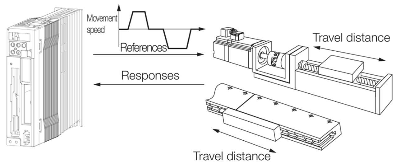
The moment of inertia during operation is automatically calculated by the servo driver for round-trip forward and reverse) operation. A reference from the host controller is not used.
The moment of inertia ratio (i.e., the ratio of the load moment of inertia to the motor moment of inertia) is a basic parameter for adjusting gains. It must be set as accurately as possible.Although the load moment of inertia can be calculated from the weight and structure of the mechanisms, doing so is very troublesome and calculating it accurately can be very difficult with the complex mechanical structures that are used these days. With moment of inertia estimation, you can get an accurate load moment of inertia simply by operating the Servomotor in the actual system in forward and reverse a few times.
The Servomotor is operated with the following specifications.
• Maximum speed: ±1,000 min-1 (can be changed)
• Acceleration rate: ±20,000 min-1/s (can be changed)
• Travel distance: ±2.5 rotations max. (can be changed)
NOTE: Execute moment of inertia estimation
after jogging to a position that ensures a
suitable range of motion.
12.5.2 Restrictions
The following restrictions apply to estimating the moment of inertia.
Systems for which Execution Cannot Be Performed
• When the machine system can move only in one direction
• When the range of motion is 0.5 rotations or less
Systems for Which Adjustments Cannot Be Made Accurately
• When a suitable range of motion is not possible
• When the moment of inertia changes within the set operating range
• When the machine has high dynamic friction
• When the rigidity of the machine is low and vibration occurs when positioning is performed
• When the position integration function is used
• When proportional control is used
NOTE:If you specify calculating the moment of inertia, an error will occur if the /P-CON (Proportional Control) signal changes to specify the
proportional action during moment of inertia estimation





• When mode switching is used
NOTE:If you specify moment of inertia estimation, mode switching will be disabled and PI control will be used while the moment of inertia is being calculated. Mode switching will be enabled after moment of inertia estimation has been completed.
• When speed feedforward or torque feedforward is input
Preparations
Always check the following before you execute moment of inertia estimation.
• The main circuit power supply must be ON.
• There must be no overtravel.
• The servo must be OFF.
• The control method must not be set to torque control.
• The gain selection switch must be set to manual gain selection (Pn139 = n.▯▯▯0). • The first gains must be selected.
• There must be no alarms or warnings.
• There must be no hard wire base block (HWBB).
• The parameters must not be write prohibited.
• The tuning-less function must be disabled (Pn170 = n.▯▯▯0).
12.5.3 Applicable Tools
The following table lists the tools that you can use to estimate the moment of inertia.
|
Tool |
Fn No./Function Name |
Operating Procedure Reference |
|
Panel Operator |
You cannot estimate the moment of inertia from the Panel Operator. |
|
|
Protuner |
[Tuning] -[Tuning] |
Operating Procedure |
12.5.4 Operating Procedure
Use the following procedure to estimate the moment of inertia ratio.
WARNING
Estimating the moment of inertia requires operating the Servomotor and therefore presents hazards. Observe the
following precautions.
•Confirm safety around moving parts.
This function involves automatic operation with vibration. Make sure that you can perform an emergency stop (to turn OFF the power supply) at any time. There will be movement in both directions within the set range of movement. Check the range of movement and the directions and implement protective controls for safety, such as the overtravel functions.。
CAUTION
Be aware of the following points if you cancel the moment of inertia estimation while the Servomotor is operating. •If you cancel operation with the Servo OFF Button, the Servomotor will stop according to setting of the Servo OFF stopping method (Pn001 = n.▯▯▯X).
•If you cancel operation with the Cancel Button, the Servomotor will decelerate to a stop and then enter a zero-clamped state.
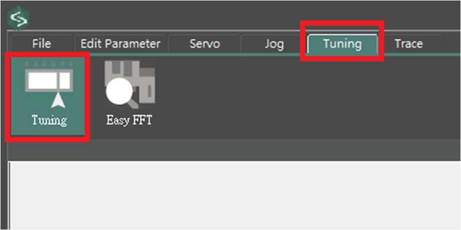
1. Select Tuning in the Menu Dialog Box.
The Tuning Dialog Box will be displayed.
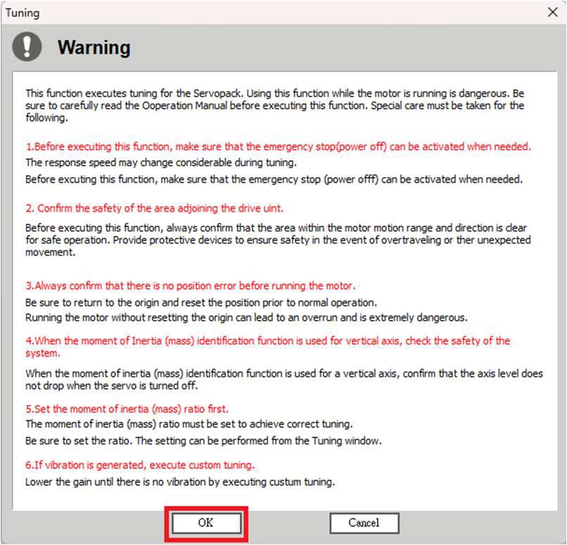
2. Click the OK Button.
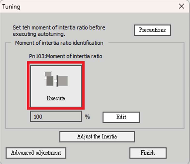
3. Click the Execute Button.
4. Set the conditions as required.
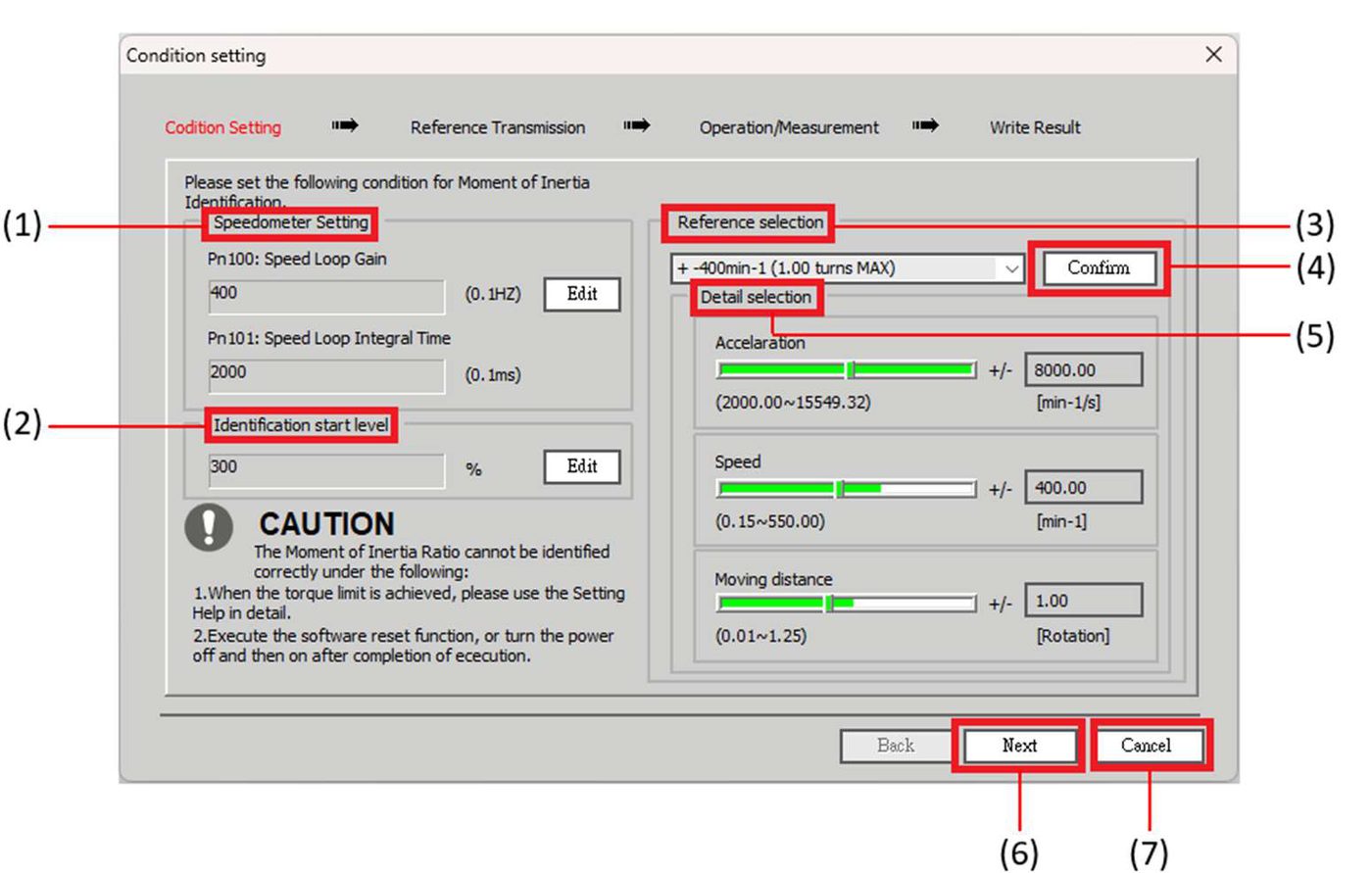



(1) [Speed Loop Setting]
Make the speed loop settings in this area.
If the speed loop response is too bad, it will not be possible to measure the moment of inertia ratio accurately.
The values for the speed loop response that are required for moment of inertia estimation are set for the default settings. It is normally not necessary to change these settings. If the default speed loop gain is too high for the machine (i.e., if vibration occurs), lower the setting. It is not necessary to increase the setting any farther.
(2) [Identification Start Level]
This is the setting of the moment of inertia calculation starting level.
If the load is large or the machine has low rigidity, the torque limit may be applied, caus-ing moment of inertia estimation to fail. If that occurs, estimation may be possible if you double the setting of the start level.
(3) [Reference Selection]
Either select the reference pattern for estimation processing from the box, or set the val-ues in the Detailed Setting Group. Generally speaking, the larger the maximum acceler-ation rate is, the more accurate the moment of inertia estimation will be.
Set the maximum acceleration range within the possible range of movement considering the gear ratio, e.g., the pulley diameters or ball screw pitch.
(4) [Confirm]
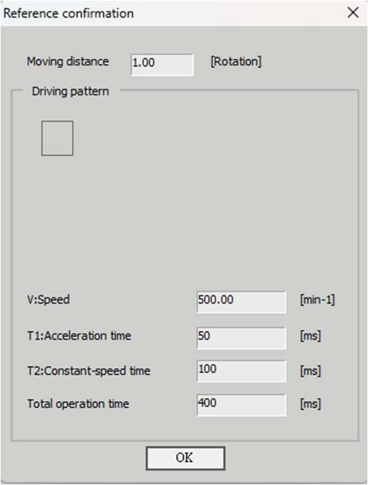
Click this button to display the Reference Confirmation Dialog Box.
(5) [Detailed Setting]
You can change the settings by moving the bars or directly inputting the settings to cre-ate the required reference pattern.
(6) [Next]
(7) [Cancel]
Click this button to return to the Tuning Dialog Box.
CAUTION
The travel distance is the distance for one operation in the forward or reverse direction. During multiple operations, the operation starting position may move in one direction or the other. Confirm the possible operating range for each measurement or operation.
Depending on the parameter settings and the moment of inertia of the machine, overshooting and undershooting may occur and may cause the maximum speed setting to be exceeded temporarily. Allow sufficient leeway in the settings.
NOTE: Estimating the moment of inertia ratio cannot be performed correctly if the torque limit is activated. Adjust the limits or reduce the acceleration rate in the reference selection so that the torque limit is not activated.。
5. Click the Next Button.
The Reference Transmission Dialog Box will be displayed.
6. Click the Start Button
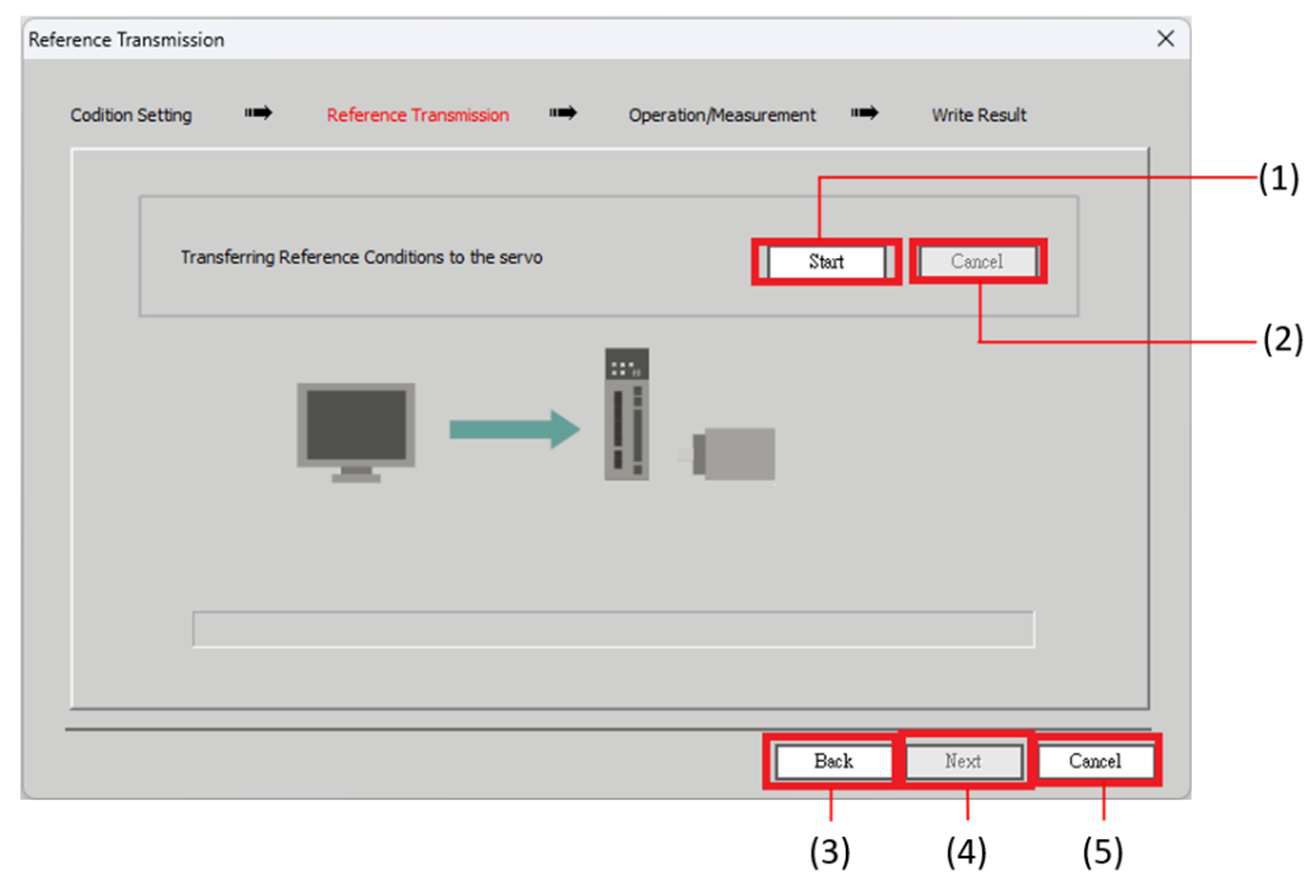
(1) [Start]
The reference conditions will be transferred to the servo driver. A progress bar will show the progress of the transfer.
(2) [Cancel]
The Cancel Button is enabled only while data is being transferred to the servo driver. You cannot use it after the transfer has been completed.
(3) [Back]
This button returns you to the Condition Setting Dialog Box. It is disabled while data is being transferred.
(4) [Next]
This button is enabled only when the data has been transferred correctly. You cannot use it if an error occurs or if you cancel the transfer before it is completed.
Click the Next Button to display the Operation/Measurement Dialog Box.。
(5) [Cancel]
This button cancels processing and returns you to the Tuning Dialog Box.
7. Click the Next Button.
The Operation/Measurement Dialog Box will be displayed.
8. Click the Servo On Button.
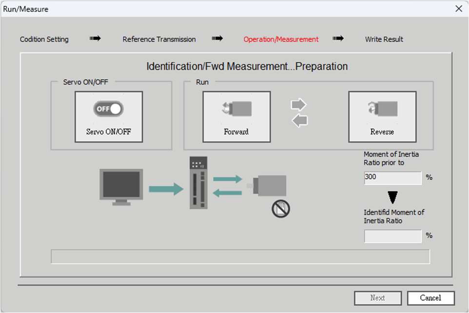
9. Click the Forward Button.
The Servomotor shaft will rotate in the forward direction and the measurement will start.
10. Click the Reverse Button.
The Servomotor shaft will rotate in the reverse direction and the measurement will start. After the measurement and data
transfer have been completed, the Forward Button will be displayed in color.
11. Repeat steps 8 to 9 until the Next Button is enabled.
Measurements are performed from 2 to 7 times and then verified. The number of measurements is displayed in upper left
corner of the dialog box.
12. When the measurements have been completed, click the Servo On Button to turn OFFthe servo.
13. Click the Next Button.
The Write Results Dialog Box will be displayed.
14. Click the Writing Results Button.
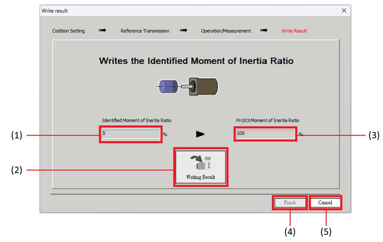
(1)[Identified Moment of Inertia Ratio]
The moment of inertia ratio that was found with operation and measurements is dis-played here.
(2) [Writing Results]
If you click this button, Pn103 (Moment of Inertia Ratio) in the servo driver is set to the value that is displayed for the identified moment of inertia ratio.
(3) [Pn103: Moment of Inertia Ratio Box]
The value that is set for the parameter is displayed here.
After you click the Writing Results Button, the value that was found with operation andmeasurements will be displayed as the new setting.。
(4)[Finish]
(5) [Cancel]
This button will return you to the Tuning Dialog Box.
15. Confirm that the Identified Moment of Inertia Ratio Box and the Pn103: Moment of Inertia Ratio Box show the same value and then click the Finish Button.
16. Click the Execute Button.
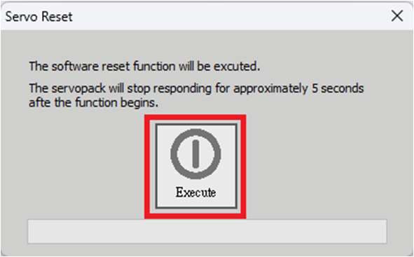
If the setting of the moment of inertia ratio (Pn103) was changed, the new value will be saved and the Tuning Dialog
Box will be displayed again.。
12.6 Autotuning without Host Reference
This section describes autotuning without a host reference.
Pn140 = n.▯▯▯0 (Do not use model following control.) |

12.6.1 Outline
The following items are adjusted automatically.
• Moment of inertia ratio
• Gains (e.g., speed loop gain and position loop gain)
• Filters (torque reference filter and notch filters)
• Friction compensation
• Anti-resonance control
• Vibration suppression (only for mode 2 or 3)
The Servomotor is operated with the following specifications.
|
Maximum speed |
Rated motor speed × 2/3 |
|
|
Acceleration Torque |
Rated motor torque: Approx. 100% |
|
|
Travel Distance |
Rotary Servomotors |
You can set the desired travel distance. The default setting is for a value equivalent to 3 Servomotor shaft rotations. |
|
Direct Drive Servomotors |
You can set the desired travel distance. The default setting is for a value equivalent to 0.3 rotations. |
|
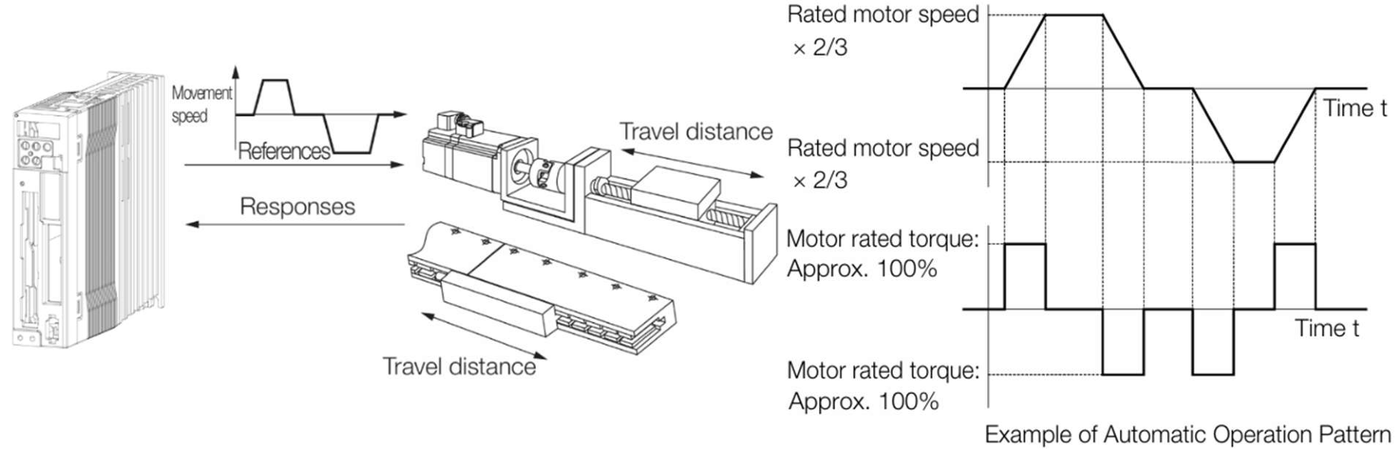
NOTE: Execute autotuning without a host reference after jogging to
a position that ensures a suitable range of motion.。


WARNING
Autotuning without a host reference requires operating the Servomotor and therefore presents hazards.
Observe the following precaution.
•Confirm safety around moving parts.
This function involves automatic operation with vibration. Make sure that you can perform an emergency stop (to turn OFF the power supply) at any time. There will be movement in both directions within the set range of movement. Check the range of movement and the directions and implement protective controls for safety, such as the overtravel functions.
12.6.2 Restrictions
The following restrictions apply to autotuning without a host reference.
Systems for Which Execution Cannot Be Performed
• When the machine system can move only in one direction
• When the range of motion is 0.5 rotations or less
Systems for Which Adjustments Cannot Be Made Accurately
• When a suitable range of motion is not possible
• When the moment of inertia changes within the set operating range
• When the machine has high friction
• When the rigidity of the machine is low and vibration occurs when positioning is performed • When the position integration function is used
• When proportional control is used
NOTE: If you specify calculating the moment of inertia, an error will occur if the /P-CON (Proportional Control) signal changes to specify the proportional action during moment of inertia estimation.
• When mode switching is used
NOTE:If you specify moment of inertia estimation, mode switching will be disabled and PI control will be used while the moment of inertia is being calculated. Mode switching will be enabled after moment of inertia estimation has been completed.。
• When speed feedforward or torque feedforward is input
• When the positioning completed width (Pn522) is too narrow
Preparations
Always check the following before you execute autotuning without a host reference.
• The main circuit power supply must be ON.
• There must be no overtravel.
• The servo must be OFF
• The control method must not be set to torque control.
• The gain selection switch must be set to manual gain selection (Pn139 = n.▯▯▯0).
• The first gains must be selected.
• There must be no alarms or warnings.
• There must be no hard wire base block (HWBB).
• The parameters must not be write prohibited.”
• The tuning-less function must be disabled (Pn170 = n.▯▯▯0), or the tuning-less function must be enabled (Pn170 = n.▯▯▯1) (default setting) and moment of inertia estimation must be specified. ”
• If you execute autotuning without a host reference during speed control, set the mode to 1.
NOTE: If you start autotuning without a host reference while the servo driver is in speed control for mode 2 or 3, the servo driver will change to position control automatically to perform autotuning without a host reference. The servo driver will return to speed control after autotuning has been completed.。
Reference pulse input multiplication switching is disabled during autotuning without a host reference.



12.6.3 Applicable Tools
|
Tool |
Fn No./Function Name |
Operating Procedure Reference |
|
Panel Operator |
− |
You cannot perform autotuning without a host reference from the Panel Operator. |
|
Digital Operator |
Fn201 |
Operator Operating Manual |
|
Protuner |
[Tuning] - [Tuning] |
Operating Procedure |
12.6.4 Operating Procedure
Use the following procedure to perform autotuning without a host reference.
CAUTION
If you specify not estimating the moment of inertia, set the moment of inertia ratio (Pn103) correctly. If the setting greatly differs from the actual moment of inertia ratio, normal control of the machine may not be possible, and vibration may result.。
If you are using a SC3 If you are using a,set the mode selection to 1. If 2 or 3 is selected for the mode, correct phase control may not be possible.
1. Confirm that the moment of inertia ratio (Pn103) is set correctly.
2. Select Tuning in the Menu Dialog Box.
The Tuning Dialog Box will be displayed.
Click the Cancel Button to cancel tuning.
3. Click the OK Button.
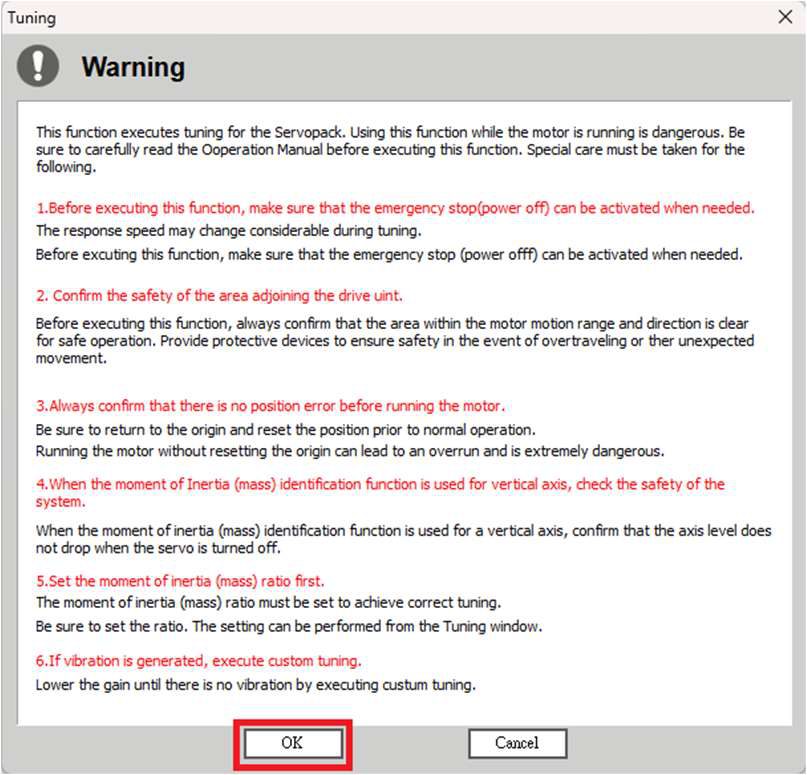
4. Select the No Reference Input Option in the Autotuning Area and then click the Auto-tuning Button.。
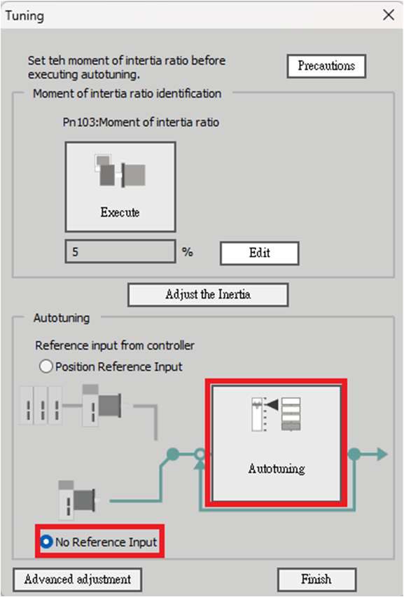
5. Set the conditions in the Switching the load moment of inertia (load mass) identifica-tion Box, the Mode selection Box,the Mechanism selection Box, and the Distance Box, and then click the Next Button.
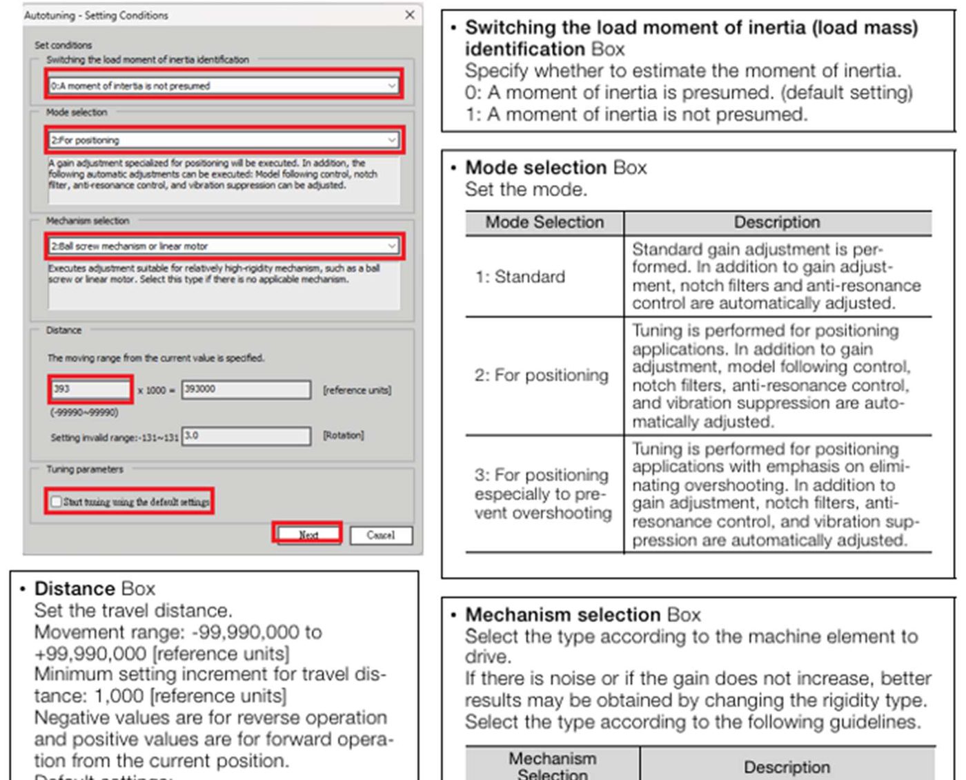
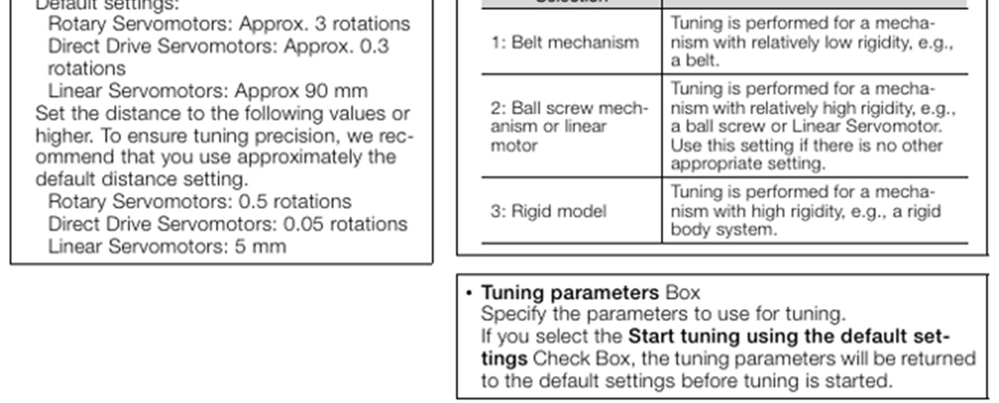
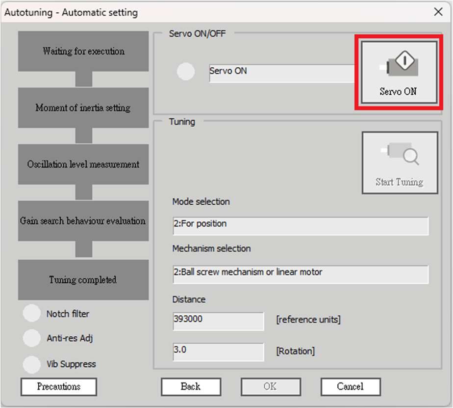
6. Click the Servo ON Button.
7. Click the Start tuning Button.
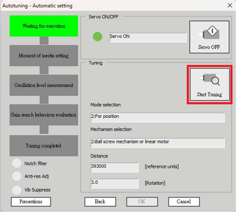
The Servomotor will start operating and tuning will be executed.
When the settings have been completed, the indicators for the functions that were used will light at the lower left of the dialog box.
8. When tuning has been completed, click the Finish Button.
The results of tuning will be set in the parameters and you will return to the Tuning Dialog Box.
This concludes the procedure to perform autotuning without a host reference.
12.6.5 Troubleshooting Problems in Autotuning without a Host Reference
The following tables give the causes of and corrections for problems that may occur in autotuning without a host reference. Autotuning without a Host Reference Was Not Performed
|
Possible Cause |
Corrective Action |
|
Main circuit power supply is OFF. |
Turn ON the main circuit power supply. |
|
An alarm or warning occurred. |
Remove the cause of the alarm or warning. |
|
Overtraveling occurred. |
Remove the cause of overtraveling. |
|
The second gains were selected with the gain selection. |
Disable automatic gain switching. |
|
The HWBB was activated. |
Release the HWBB. |
|
The setting of the travel distance is too small. |
Set the travel distance again in step 6 of the procedure. |
|
The settings for the tuning-less function are not correct. |
• Disable the tuning-less function (Pn170 = n.▯▯▯0). • Enable the tuning-less function (Pn170 = n.▯▯▯1) and specify moment of inertia estimation. |
When an Error Occurs during Execution of Autotuning without a Host Reference
|
Error |
Possible Cause |
Corrective Action |
|
The gain adjustments were not successfully completed. |
Machine vibration occurs or the positioning |
• Increase the setting of the positioning completed width (Pn522). • Change the mode from 2 to 3. • If machine vibration occurs, suppress the vibration with the anti-resonance control adjustment and the vibration suppression function. |
|
An error occurred during calculation of the moment of inertia. |
Refer to the following section for troubleshooting information. When an Error Occurs during Calculation of Moment of Inertia |
|
|
Positioning was not completed within approximately 10 seconds after position adjustment was completed. |
The positioning completed width is too narrow or |
• Increase the setting of the positioning completed width (Pn522). • Turn OFF the /P-CON (Proportional Control) signal. |
When an Error Occurs during Calculation of Moment of Inertia
|
Possible Cause |
Corrective Action |
|
The servo driver started calculating the moment of inertia but the calculation was not completed. |
• Increase the setting of the speed loop gain (Pn100). • Increase the stroke (travel distance). |
|
The moment of inertia fluctuated greatly and did not converge within 10 tries. |
Set Pn103 (Moment of Inertia Ratio) from the machine specifications and specify not estimating the moment of inertia. |
|
Low-frequency vibration was detected. |
Double the setting of moment of inertia calculation starting level (Pn324). |
|
The torque limit was reached. |
• If you are using the torque limit, increase the torque limit. • Double the setting of moment of inertia calculation starting level (Pn324). |
|
The speed control section changed to |
Use PI control when calculating the moment of inertia. |
Adjustment Results Are Not Satisfactory for Position Control
You may be able to improve the adjustment results by changing the settings of the positioning completed width (Pn522) and the electronic gear ratio (Pn20E/Pn210).
• Pn561 = 100% (default setting)
• This will allow tuning with overshooting that is equivalent to the positioning completed width.
• Pn561 = 0%
This will allow tuning to be performed without overshooting within the positioning completed width.
|
Pn561 |
Overshoot Detection Level
|
Speed |
ab |
Pos |
ition |
ss |
Torque |
||||||
|
led |
Classification |
||||||||||||
|
0 ~ 100 |
1% |
100 |
Classification |
Setup |
|||||||||
12.6.6 Automatically Adjusted Function Settings
You can specify whether to automatically adjust the following functions during autotuning. ◆Automatic Notch Filters
Normally, set Pn460 to n.▯1 ▯▯ (Adjust automatically) (default setting).
Vibration will be detected during autotuning without a host reference and a notch filter will be adjusted. Set Pn460 to n.▯0 ▯▯ (Do not adjust automatically) only if you do not change the setting of the notch filter before you execute this function.
|
Parameter |
Function |
When Enabled |
Classification |
|
|
Pn460 |
n.▯▯▯0 |
Do not adjust the first stage notch filter auto matically during execution of autotuning with out a host reference, autotuning with a host reference, and custom tuning. |
Immediately |
Tuning |
|
n.▯▯▯1 |
Adjust the first stage notch filter |
|||
|
n.▯0▯▯ |
Do not adjust the second stage notch filter automatically when the tuning-less function is enabled or during execution of autotuning without a host reference, autotuning with a host reference, and custom tuning. |
|||
|
n.▯1▯▯ |
Adjust the second stage notch filter |
|||
|
◆ |
Anti-Resonance Control Adjustment |
|
This function reduces low vibration frequencies, for which the notch filters cannot be used. |
|
Normally, set Pn160 to n.▯▯1 ▯ (Adjust automatically) (default setting).
Vibration will be detected during autotuning without a host reference and anti-resonance control will be automatically adjusted.。
|
Parameter |
Function |
When Enabled |
Classification |
|
|
Pn160 |
n.▯▯0▯ |
Do not adjust anti-resonance control |
Immediately |
Tuning |
|
n.▯▯1▯ |
Adjust anti-resonance control automatically during execution of autotuning without a host reference, autotuning with a host reference, and custom tuning. |
|||
|
◆ |
Vibration Suppression |
You can use vibration suppression to suppress transitional vibration at a low frequency from 1 Hz to 100 Hz, which is generated mainly when the machine vibrates during positioning.
Normally, set Pn140 to n.▯1 ▯▯ (Adjust automatically) (default setting). Vibration will be detected during autotuning without a host reference and vibration suppression control will be automatically set.
Set Pn140 = n.▯0 ▯▯ (Do not adjust automatically) only if you do not change the settings for vibration suppression before you execute autotuning without a host reference.
NOTE: Autotuning without a host reference uses model following control. Therefore, it can be executed only if the mode is set to 2 or 3.。
|
Parameter |
Function |
When Enabled |
Classification |
|
|
Pn140 |
n.▯0▯▯ |
Do not adjust vibration suppression |
Immediately |
Tuning |
|
n.▯1▯▯ |
Adjust vibration suppression automatically during execution of autotuning without a host reference, autotuning with a host reference, and custom tuning. |
|||



◆ Friction Compensation
Friction compensation compensates for changes in the following conditions.
• Changes in the viscous resistance of the lubricant, such as grease, on the sliding parts of the machine
• Changes in the friction resistance resulting from variations in the machine assembly
• Changes in the friction resistance due to aging
The conditions for applying friction compensation depend on the mode selection.
|
Mode Selection Settings |
Friction Compensation |
|
1:Standard |
Based on the setting of Pn408 = n.X▯▯▯ (Friction Compensation Function Selection)* |
|
2:For position control |
Adjusted with friction compensation. |
|
3:For position control (emphasis on overshooting) |
|
Parameter |
Function |
When Enabled |
Classification |
|
|
Pn408 |
n.0▯▯▯ |
Disable friction compensation. |
Immediately |
Setup |
|
n.1▯▯▯ |
Enable friction compensation. |
|||
* Refer to the following section for details.
◆ Feedforward
If Pn140 is set to n.0 ▯▯▯ (Do not use model following control and speed/torque feedforward together
(default setting)) and tuning is performed with the mode selection set to 2 or 3, feedforward (Pn109), the speed feedforward
input (V-REF), and the torque feedforward input (TREF) will be disabled.
To use the speed feedforward input (V-REF), the torque feedforward input (T-REF), and model following control from the host
controller in the system, set Pn140 to n.1 ▯▯▯ (Use model following control and speed/torque feedforward together).
|
Parameter |
Function |
When Enabled |
Classification |
|
|
Pn140 |
n.0▯▯▯ |
Do not use model following control and speed/torque feedforward together. |
Immediately |
Setup |
|
n.1▯▯▯ |
Use model following control and speed/torque feedforward together. |
|||
Refer to the following section for information on the torque feedforward input (T-REF) and the speed feedforward input (V-REF).
When model following control is used with the feedforward function, it is used to make optimum feedforward settings in the
ServoDriver. Therefore, model following control is not normally used together with either the speed feedforward input (V-REF)
or torque feedforward input (T-REF) from the host controller. However, model following control can be used with the speed
feedforward input (V-REF) or torque feedforward input (T-REF) if required. An unsuitable feedforward input may result in
overshooting.。
12.6.7Related Parameters
The following parameters are automatically adjusted or used as reference when you execute autotuning without a host reference.
Do not change the settings while autotuning without a host reference is being executed.
|
Parameter Pn100 |
Name |
Automatic Changes |
|
Speed Loop Gain |
Yes |
|
|
Pn101 |
Speed Loop Integral Time Constant |
Yes |
|
Pn102 |
Position Loop Gain |
Yes |
|
Pn103 |
Moment of Inertia Ratio |
Yes |
|
Pn121 |
Friction Compensation Gain |
Yes |
|
Pn123 Pn124 Pn125 |
Friction Compensation Coefficient |
Yes |
|
Friction Compensation Frequency Correction |
No |
|
|
Friction Compensation Gain Correction |
Yes |
|
|
Pn401 |
First Stage First Torque Reference Filter Time Constant |
Yes |
|
Pn408 |
Torque-Related Function Selections |
Yes |
|
Pn409 |
First Stage Notch Filter Frequency |
Yes |
|
Pn40A |
First Stage Notch Filter Q Value |
Yes |
|
Pn40C |
Second Stage Notch Filter Frequency |
Yes |
|
Pn40D |
Second Stage Notch Filter Q Value |
Yes |
|
Pn140 |
Model Following Control-Related Selections |
Yes |
|
Pn141 |
Model Following Control Gain |
Yes |
|
Pn142 |
Model Following Control Gain Correction |
Yes |
|
Pn143 |
Model Following Control Bias in the Forward Direction |
Yes |
|
Pn144 |
Model Following Control Bias in the Reverse Direction |
Yes |
|
Pn145 |
Vibration Suppression 1 Frequency A |
Yes |
|
Pn146 |
Vibration Suppression 1 Frequency B |
Yes |
|
Pn147 |
Model Following Control Speed Feedforward Compensation |
Yes |
|
Pn160 |
Anti-Resonance Control-Related Selections |
Yes |
|
Pn161 |
Anti-Resonance Frequency |
Yes |
|
Pn163 |
Anti-Resonance Damping Gain |
Yes |
|
Program Jogging Travel Distance |
No |
|
|
Pn533 |
Program Jogging Movement Speed for Rotary Servomotor |
No |
|
Pn585 |
Program Jogging Movement Speed for Linear Servomotor |
No |
|
Pn534 |
Program Jogging Acceleration/Deceleration Time |
No |
|
Pn535 |
Program Jogging Waiting Time |
No |
|
Pn536 |
Program Jogging Number of Movements |
No |
Yes: The parameter is automatically set.
No: The parameter is not automatically set, but the setting is read during execution.




12.7 Autotuning with a Host Reference
This section describes autotuning with a host reference.
|
Autotuning with a host reference makes adjustments based on the set speed loop gain (Pn100). Therefore, precise adjustments cannot be made if there is vibration when adjustments are started. Make adjustments after lowering the speed loop gain (Pn100) until vibration is eliminated.。 |
12.7.1 Outline
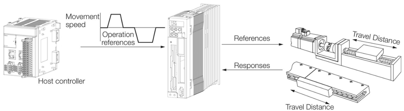
Autotuning with a host reference automatically makes optimum adjustments for operation
references from the host controller.。
The following items are adjusted automatically.
• Gains (e.g., speed loop gain and position loop gain)
• Filters (torque reference filter and notch filters)
• Friction compensation
• Anti-resonance control
• Vibration suppression
Refer to the following section for details on the parameters that are adjusted.
CAUTION
Because autotuning with a host reference adjusts the SERVOPACK during automatic operation, vibration or overshooting may occur. To ensure safety, make sure that you can perform an emergency stop at any time.。
12.7.2Restrictions
Systems for Which Adjustments Cannot Be Made Accurately
Adjustments will not be made correctly for autotuning with a host reference in the following cases.
Use custom tuning.
• When the travel distance for the reference from the host controller is equal to or lower than the setting of the positioning completed width (Pn522)
• Rotary Servomotors: When the movement speed for the reference from the host controller is equal to or lower than the setting of the rotation detection level (Pn502)
• Linear Servomotors: When the movement speed for the reference from the host controller is equal to or lower than the setting of the zero speed level (Pn581)
• When the time required to stop is 10 ms or less
• When the rigidity of the machine is low and vibration occurs when positioning is performed
• When the position integration function is used
• When proportional control is used
• When mode switching is used
• When the positioning completed width (Pn522) is too narrow



Preparations
Always check the following before you execute autotuning with a host reference.
• The servo must be in ready status.
• There must be no overtravel.。
• The servo must be OFF.
• Position control must be selected if power is supplied to the motor (i.e., when the servo is ON). • The gain selection switch must be set to manual gain selection (Pn139 = n.▯▯▯0).
• The first gains must be selected.
• There must be no warnings.
• The tuning-less function must be disabled (Pn170 = n.▯▯▯0).
• The parameters must not be write prohibited.
12.7.3Applicable Tools
The following table lists the tools that you can use to perform autotuning with a host reference.
|
Tool |
Fn No./Function Name |
Operating Procedure Reference |
|
Panel Operator |
− |
You cannot perform autotuning without a host reference from the Panel Operator. |
|
Digital Operator |
Fn202 |
Digital Operator Operating Manual |
|
Protuner |
[Tuning] - [Tuning] |
Operating Procedure |
12.7.4 Operating Procedure
Use the following procedure to perform autotuning with a host reference.
CAUTION
If you are using an MP3000-Series Controller for phase control, set the mode selection to 1. If 2 or 3 is selected for the mode, correct phase control may not be possible.
1. Confirm that the moment of inertia ratio (Pn103) is set correctly.
2. Select Tuning in the Menu Dialog Bot
The Tuning Dialog Box will be displayed.
Click the Cancel Button to cancel tuning.
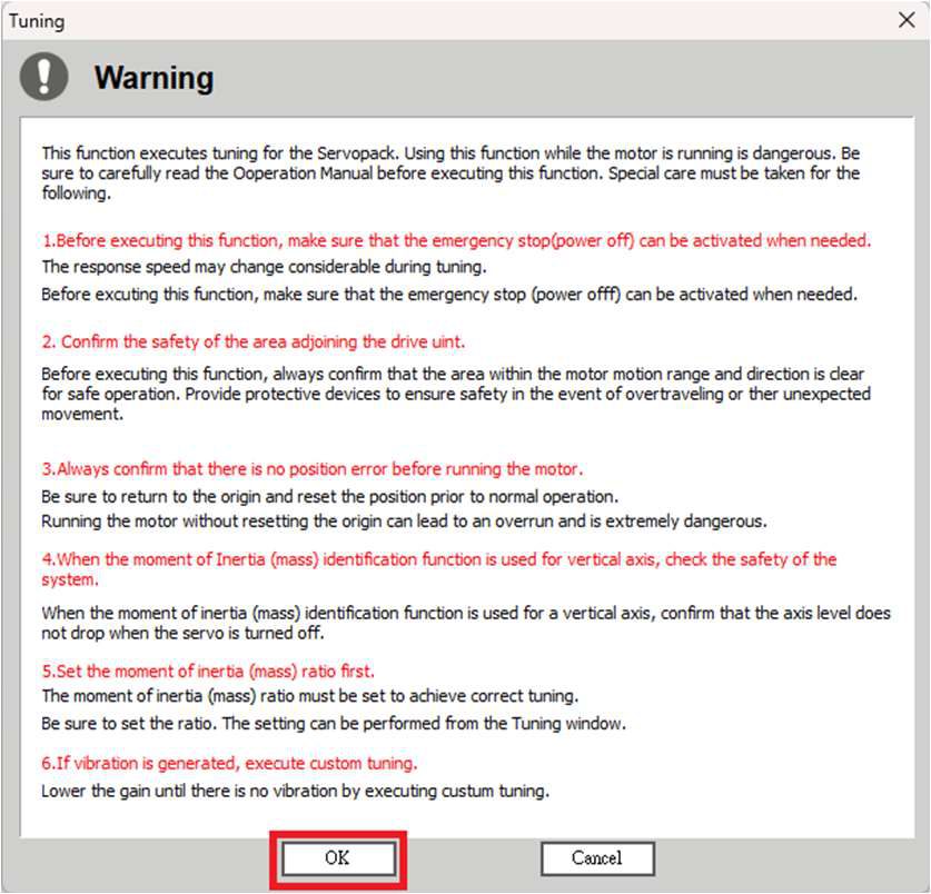
3. Click the OK Button.
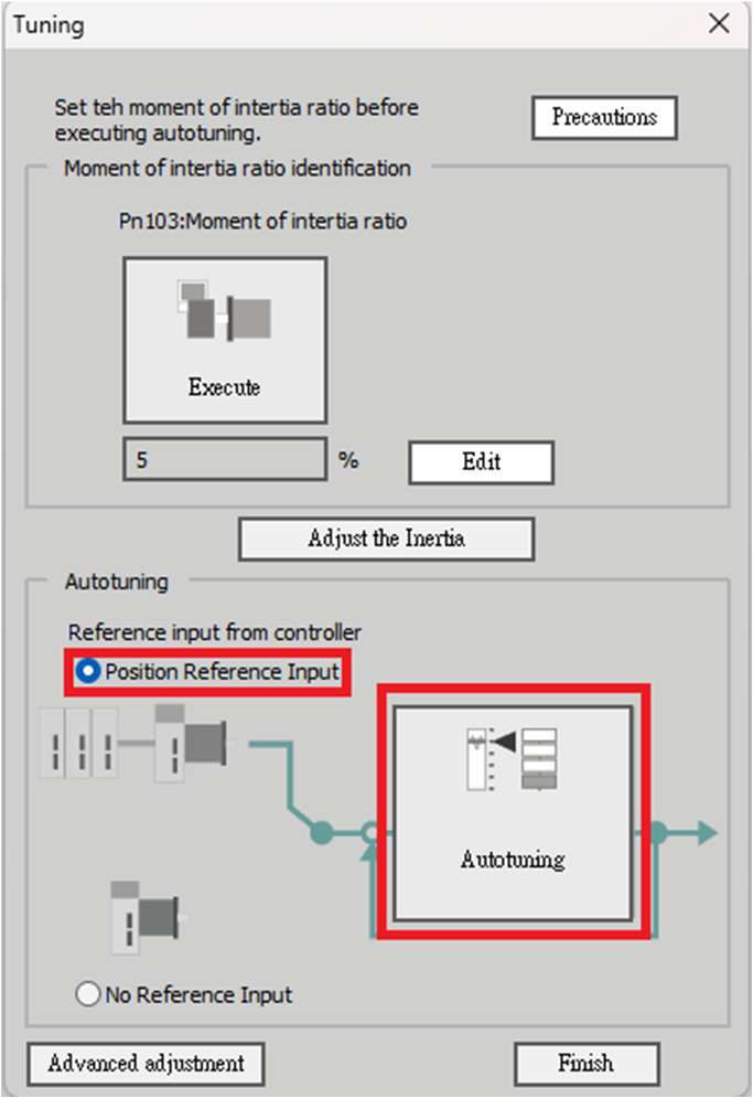
4. Select the Position reference input Option in the Autotuning Area and then click the Autotuning Button.
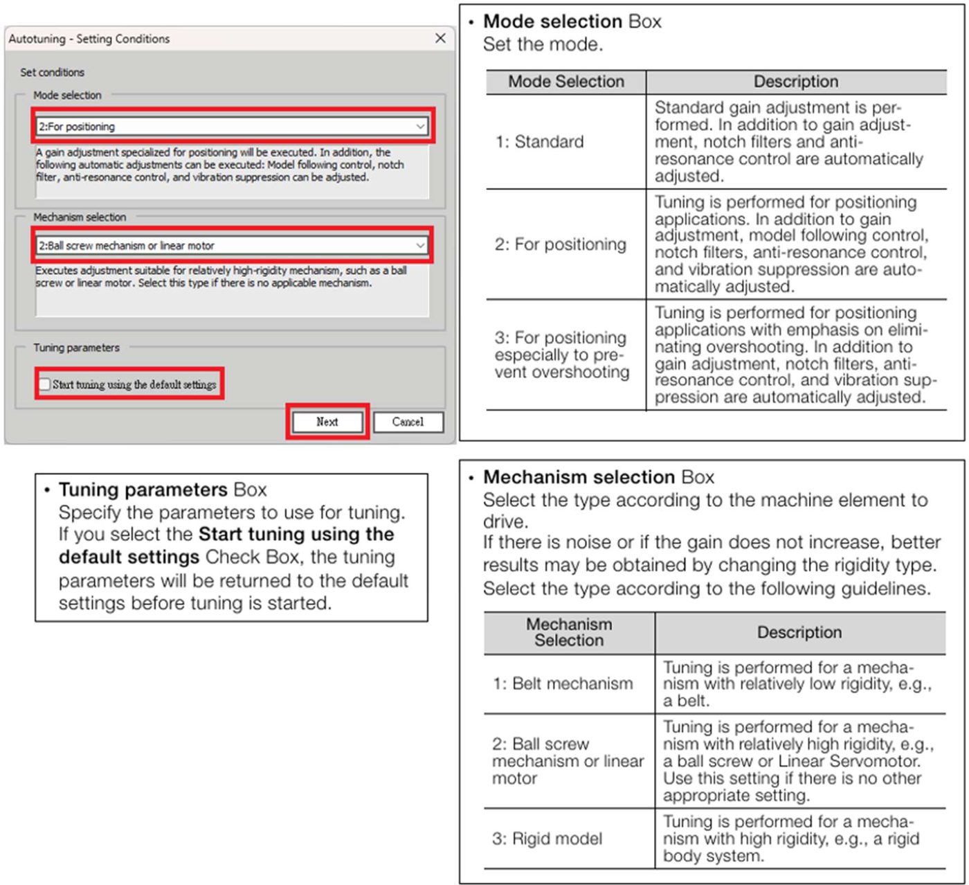
Set the conditions in the Mode selection Box and the Mechanism selection Box, and then click the Next Button.
If you select the Start tuning using the default settings Check Box in the Tuning parameters Area, the tuning parameters will be returned to the default settings before tuning is started.
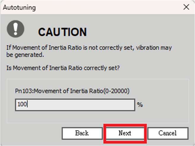
5. Input the correct moment of inertia ratio and click the Next Button.
6. First confirm safety around moving parts. Then turn ON the servo, enter a reference from the host controller
, and click the Start tuning Button.
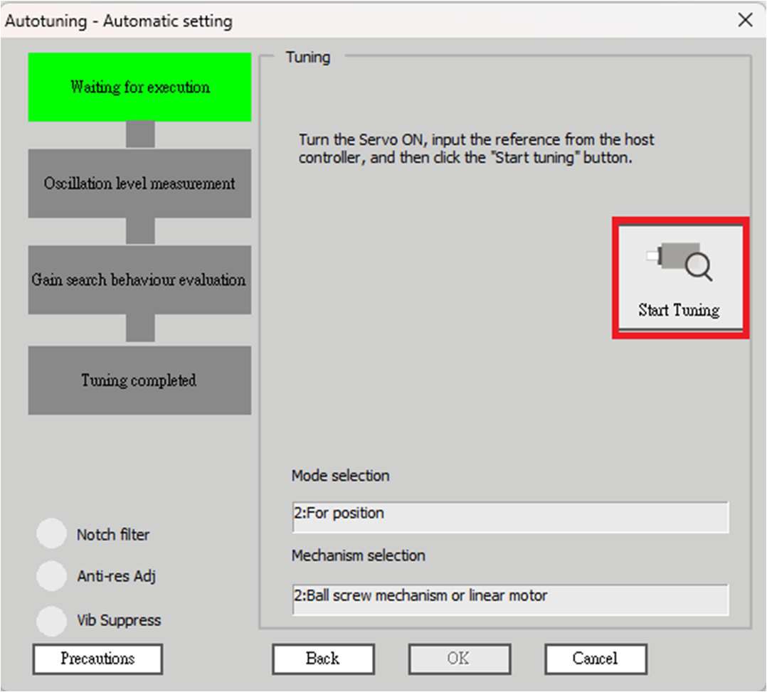
Tuning will be executed.
Vibration that occurs during tuning will be detected automatically and suitable settings will be made for that vibration. When the settings have been completed, the indicators for the functions that were used will light at the lower left of the dialog box.。
7. When tuning has been completed, click the Finish Button.
The results of tuning will be set in the parameters and you will return to the Tuning Dialog Box.
This concludes the procedure to perform autotuning with a host reference.
12.7.5 Troubleshooting Problems in Autotuning with a Host Reference
The following tables give the causes of and corrections for problems that may occur in autotuning with a host reference.
|
◆ |
Autotuning with a Host Reference Was Not Performed |
|
Possible Cause |
Corrective Action |
|
Main circuit power supply is OFF. |
Turn ON the main circuit power supply. |
|
An alarm or warning occurred. |
Remove the cause of the alarm or warning. |
|
Overtraveling occurred. |
Remove the cause of overtraveling. |
|
The second gains were selected with the gain selection. |
Disable automatic gain switching. |
|
The HWBB was activated. |
Release the HWBB. |
|
◆ |
Troubleshooting Errors |
|
Error |
Possible Cause |
Corrective Action |
|
The gain adjustments were not successfully completed. |
Machine vibration occurs or positioning completion is not stable |
• Increase the setting of the positioning completed width (Pn522). • Change the mode from 2 to 3. • If machine vibration occurs, suppress the vibration with the anti-resonance control adjustment and the vibration suppression function. |
|
Positioning was not |
The positioning completed width is too narrow or |
• Increase the setting of the positioning completed width (Pn522). • Turn OFF the /P-CON (Proportional Control) signal. |
|
◆ |
Adjustment Results Are Not Satisfactory for Position Control |
You may be able to improve the adjustment results by changing the settings of the positioning completed width (Pn522) and the electronic gear ratio (Pn20E/Pn210).
If satisfactory results are still not possible, adjust the overshoot detection level (Pn561). That may improve the adjustment results.
• Pn561 = 100% [ default setting ]
This will allow tuning with overshooting that is equivalent to the positioning completed width.
• Pn561 = 0%
This will allow tuning to be performed without overshooting within the positioning completed width, but the
positioning completed width may be extended.
|
Pn561 |
Overshoot Detection Level
|
Speed |
e |
Pos |
ition |
s |
Torque |
|||||||
|
d |
Classification |
|||||||||||||
|
0 ~ 100 |
1% |
100 |
Immediately |
Setup |
||||||||||
12.7.6 Automatically Adjusted Function Settings
These function settings are the same as for autotuning without a host reference. Refer to the following section.
12.6.6 Automatically Adjusted Function Settings
12.7.7 Related Parameters
The following parameters are automatically adjusted or used as reference when you execute autotuning with a host reference.
Do not change the settings while autotuning with a host reference is being
executed.
|
Parameter Pn100 |
Name |
Automatic Changes |
|
Speed Loop Gain |
Yes |
|
|
Pn101 |
Speed Loop Integral Time Constant |
Yes |
|
Pn102 |
Position Loop Gain |
Yes |
|
Moment of Inertia Ratio |
No |
|
|
Friction Compensation Gain |
Yes |
|
|
Pn123 |
Friction Compensation Coefficient |
Yes |
|
Friction Compensation Frequency Correction |
No |
|
|
Friction Compensation Gain Correction |
Yes |
|
|
Pn401 |
First Stage First Torque Reference Filter Time Constant |
Yes |
|
Pn408 |
Torque-Related Function Selections |
Yes |
|
Pn409 |
First Stage Notch Filter Frequency |
Yes |
|
Pn40A |
First Stage Notch Filter Q Value |
Yes |
|
Pn40C |
Second Stage Notch Filter Frequency |
Yes |
|
Pn40D |
Second Stage Notch Filter Q Value |
Yes |
|
Pn140 |
Model Following Control-Related Selections |
Yes |
|
Pn141 |
Model Following Control Gain |
Yes |
|
Pn142 |
Model Following Control Gain Correction |
Yes |
|
Pn143 |
Model Following Control Bias in the Forward Direction |
Yes |
|
Pn144 |
Model Following Control Bias in the Reverse Direction |
Yes |
|
Pn145 |
Vibration Suppression 1 Frequency A |
Yes |
|
Pn146 |
Vibration Suppression 1 Frequency B |
Yes |
|
Pn147 |
Model Following Control Speed Feedforward Compensation |
Yes |
|
Pn160 |
Anti-Resonance Control-Related Selections |
Yes |
|
Pn161 |
Anti-Resonance Frequency |
Yes |
|
Pn163 |
Anti-Resonance Damping Gain |
Yes |
Yes: The parameter is automatically set.
No: The parameter is not automatically set, but the setting is read during execution.



12.8Custom Tuning
This section describes custom tuning.
12.8.1 Outline
You can use custom tuning to manually adjust the servo during operation using a speed or position reference input from the host controller. You can use it to fine-tune adjustments that were made with autotuning.
The following items are adjusted automatically.
• Gains (e.g., speed loop gain and position loop gain)
• Filters (torque reference filter and notch filters)
• Friction compensation
• Anti-resonance control
Refer to the following section for details on the parameters that are adjusted.
There are two adjustment methods that you can use for custom tuning.
|
◆ ◆ |
Tuning Mode 0 (Setting Servo Gains Giving Priority to Stability) or 1 (Setting Servo Gains Giving Priority to Good Response) Tuning Mode 2 (Setting Servo Gains Giving Priority to Position Control Applications) or 3 (Setting Servo Gains Giving Priority to Preventing Overshooting in Position Control Applications) Two tuning levels are manipulated to reduce positioning time even further and set multiple servo gains. Model following control is used to reduce the positioning time. If vibration is detected, notch filters and anti-resonance control are automatically adjusted, and friction compensation is automatically set. Manual anti-resonance control adjustment and vibration suppression are also possible during custom tuning. |
CAUTION
Vibration or overshooting may occur during custom tuning. To ensure safety, make sure that you can perform an emergency stop at any time.
12.8.2 Preparations
Always check the following before you execute custom tuning.
• The tuning-less function must be disabled (Pn170 = n.▯▯▯0).
• If speed control is used, tuning mode 0 or 1 must be set.
• The parameters must not be write prohibited.
12.8.3Applicable Tools
The following table lists the tools that you can use to perform custom tuning.
|
Tool |
Fn No./Function Name |
Operating Procedure Reference |
|
Panel Operator |
− |
You cannot perform custom tuning from the Panel Operator. |
|
Digital Operator |
Fn203 |
Digital Operator Operating Manual |
|
Protuner |
[Tuning] - [Tuning] |
Operating Procedure |





12.8.4Operating Procedure
Use the following procedure to perform custom tuning.
WARNING
Before you execute custom tuning, check the
information provided in the ProTuner operating
manual.
Observe the following precautions.
Make sure that you can perform an emergency stop at any time.
When custom tuning is started, several parameters will be overwritten with the recommended settings, which may greatly
affect the response before and after execution. Make sure that you can perform an emergency stop at any time.
Set the moment of inertia correctly before you execute custom tuning. If the setting greatly differs from the actual
moment of inertia, vibration may occur.
If you change the feedforward level, the new setting will not be used immediately. It will be used after positioning is completed.。
CAUTION
If you are using an MP3000-series Controller for phase control, set the tuning mode to 0 or 1. If 2 or 3 is selected for the tuning mode, correct phase control may not be possible.
1. Confirm that the moment of inertia ratio (Pn103) is set correctly.
2. Select Tuning in the Menu Dialog Box.
The Tuning Dialog Box will be displayed.
Click the Cancel Button to cancel tuning.
3. Click the OK Button.
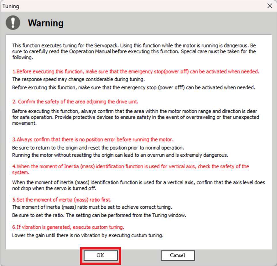
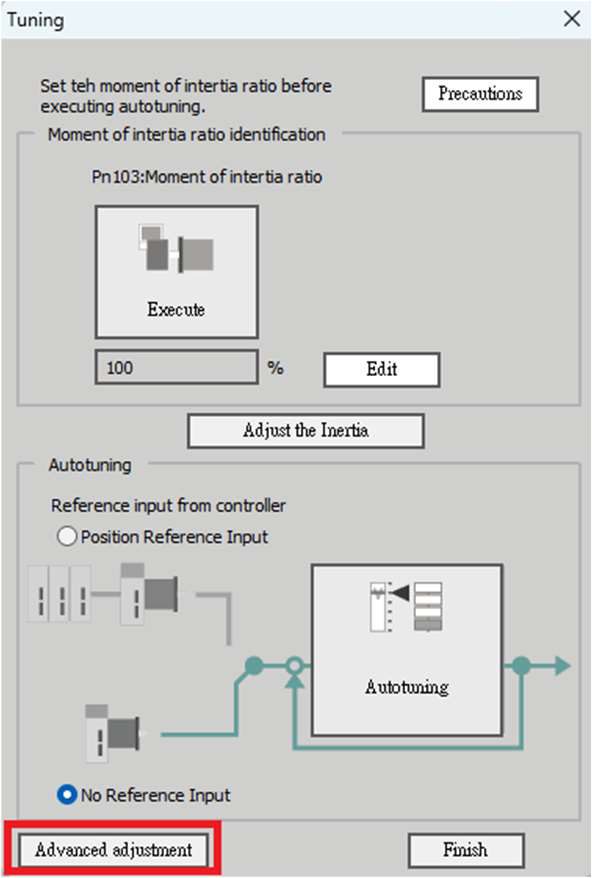
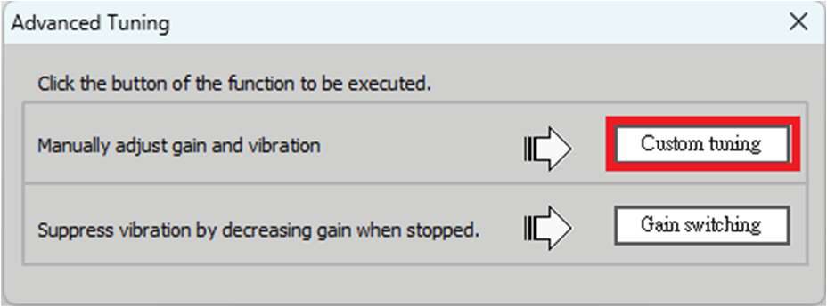
4. Click the Advanced adjustment Button.
5. Click the Custom tuning Button.
6. Set the Tuning mode Box and Mechanism selection Box, and then click the Next Button.
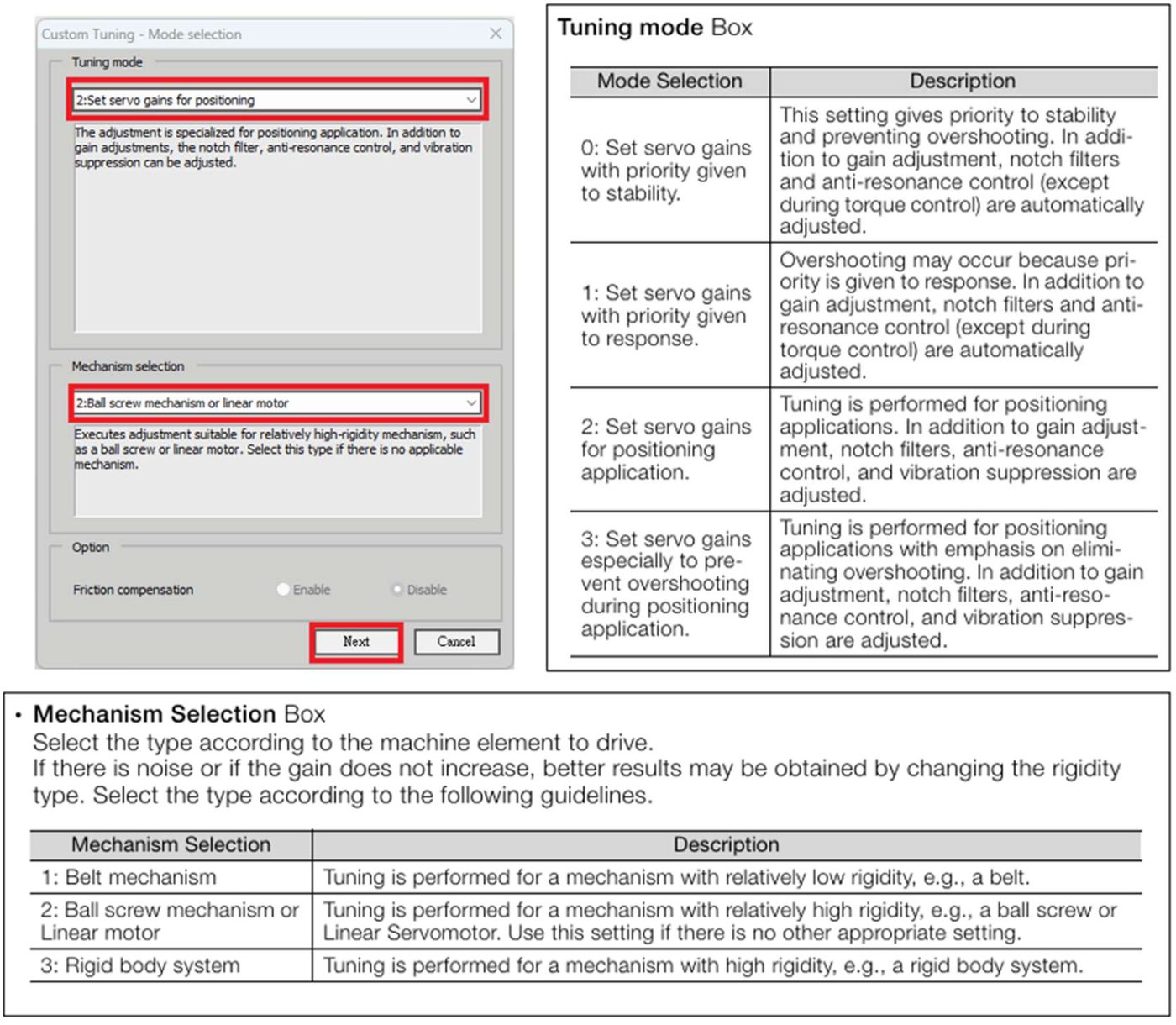
NOTE: The tuning modes that you can select depend on the servo driver setting.
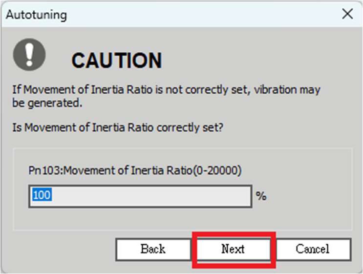
7. If the moment of inertia ratio is not set correctly, correct the setting and then click the Next Button.
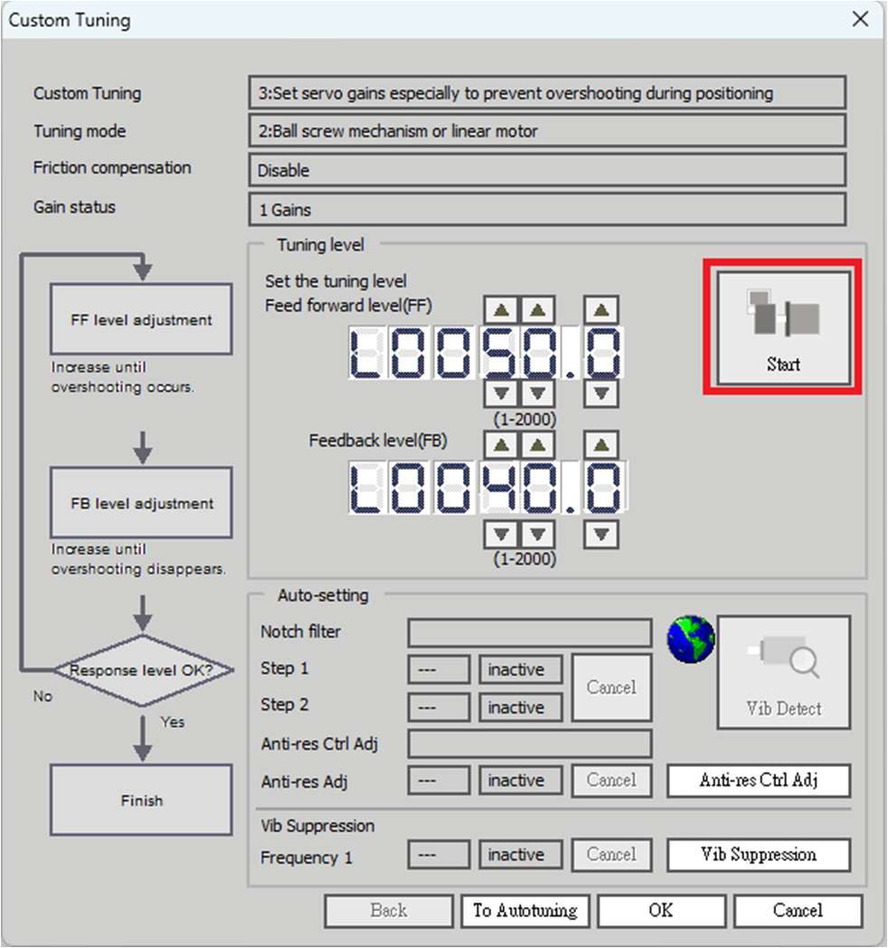
8. Turn ON the servo, enter a reference from the host controller, and then click the Start tuning Button. <Tuning Mode 0 or 1> <Tuning Mode 2 or 3>
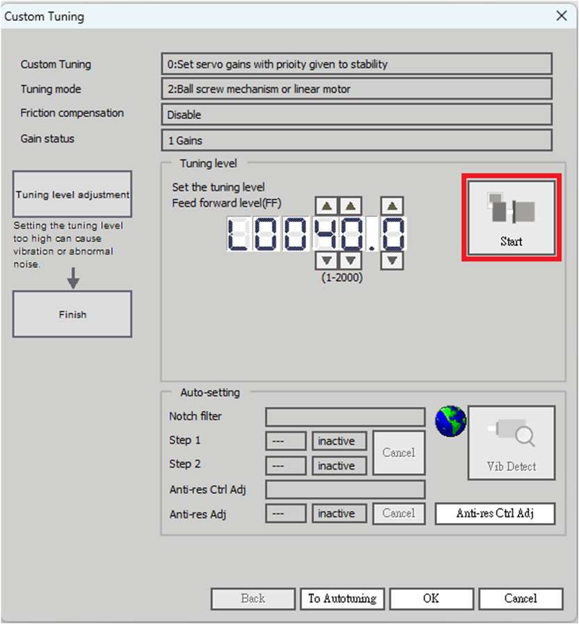
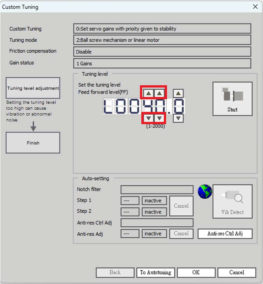
9. Use the [ ▲ ] and [ ▼ ] Buttons to change the tuning level.
Click the Back Button during tuning to restore the setting to its original value. The tuning level will return to the value from before when custom tuning was started.
<Tuning Mode 0 or 1> <Tuning Mode 2 or 3>
Increase the tuning level until
overshooting occurs.。
Increase the feedforward level until overshooting occurs and then increase the feedback level until overshooting is
eliminated. Repeat these changes to make the adjustment.。
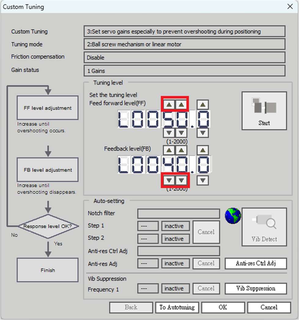
NOTE: The new feedforward level will not be used until the positioning completed signal is output.
10. You can set the functions to suppress vibration (notch filters, automatic anti-resonance control setting, anti-resonance control adjustment, and autotuning with a host reference) as required. 11. When tuning has been completed, click the OK Button.
The values that were changed will be saved in the servo driver and you will return to the Tuning Dialog Box.
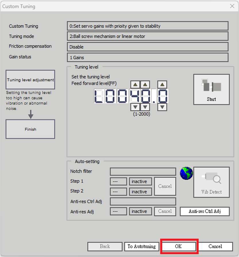
This concludes the procedure to set up custom tuning.
Vibration Suppression Functions
◆ Notch Filters and Automatic Anti-resonance Control Setting
If the vibration frequency that occurs when you increase the servo gains is at 1,000 Hz or higher, notch filters are
effective to suppress vibration. If the vibration is between 100 Hz and 1,000 Hz, anti-resonance control is effective.
◆ Automatic Setting
To set vibration suppression automatically, use the parameters to enable notch filters and automatic anti-resonance control setting.
The notch filter frequency (stage 1 or 2) or anti-resonance control frequency that is effective for the vibration that was detected
during tuning will be automatically set.
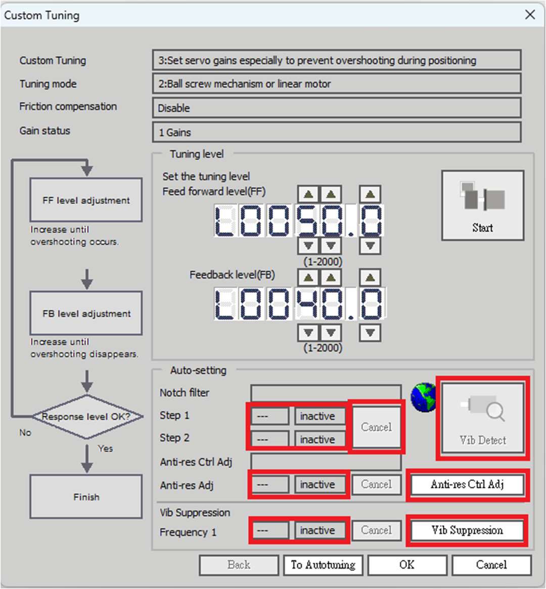
Auto-setting Cancel Buttons
The automatically set notch filter frequencies or the anti-resonance control frequencies may not always suppress vibration. Click the Cancel Button to reset the notch filter frequencies or the anti-resonance control frequencies to the values from just before these frequencies were set automatically. When they are reset, vibration detection will start again.
Vib Detect Button
While the notch filter or automatic anti-resonance control setting function is enabled, you can click the Vib Detect Button to manually detect vibration. When you click the Vib Detect Button, the servo driver will detect vibration at that time, and set the notch filter frequency (stage 1 or 2) or anti-resonance control frequency that is effective for the detected vibration. You can also perform manual vibration detection even when the servo driver does not detect vibration.
Anti-res Ctrl Adj Button
You can use the Anti-res Ctrl Adj Button to execute the anti-resonance control adjust ment if fine-tuning is required. Refer to the following section.
Vib Suppress Button
Click the Vib Suppress Button to suppress low and transient vibration (oscillation) of approximately 1 Hz to 100 Hz that occurs during positioning. Refer to the following section.
◆ Autotuning with a Host Reference
You can perform autotuning with a host reference. Refer to the following section for details.
12.8.5Automatically Adjusted Function Settings
You cannot use vibration suppression functions at the same time. Other automatic function settings are the same as for autotuning without a host reference. Refer to the following section.
12.8.6Tuning Example for Tuning Mode 2 or 3
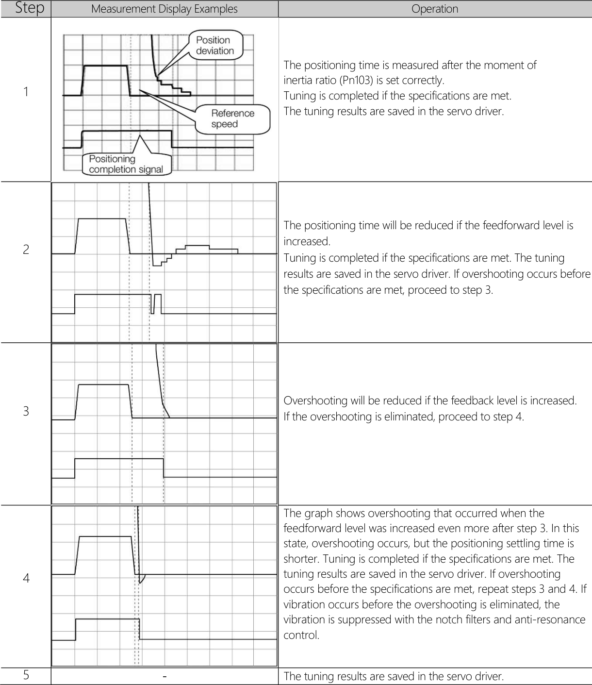
12.8.7 Related Parameters
The following parameters are automatically adjusted or used as
reference when you execute custom tuning.
Do not change the settings while custom tuning is being
executed.。
|
Parameter Pn100 |
Name |
Automatic Changes |
|
Speed Loop Gain |
Yes |
|
|
Pn101 |
Speed Loop Integral Time Constant |
Yes |
|
Pn102 Pn103 Pn121 |
Position Loop Gain |
Yes |
|
Moment of Inertia Ratio |
No |
|
|
Friction Compensation Gain |
Yes |
|
|
Pn123 Pn124 Pn125 |
Friction Compensation Coefficient |
Yes |
|
Friction Compensation Frequency Correction |
No |
|
|
Friction Compensation Gain Correction |
Yes |
|
|
Pn401 |
First Stage First Torque Reference Filter Time Constant |
Yes |
|
Pn408 |
Torque-Related Function Selections |
Yes |
|
Pn409 |
First Stage Notch Filter Frequency |
Yes |
|
Pn40A |
First Stage Notch Filter Q Value |
Yes |
|
Pn40C |
Second Stage Notch Filter Frequency |
Yes |
|
Pn40D |
Second Stage Notch Filter Q Value |
Yes |
|
Pn140 |
Model Following Control-Related Selections |
Yes |
|
Pn141 |
Model Following Control Gain |
Yes |
|
Pn142 |
Model Following Control Gain Correction |
Yes |
|
Pn143 |
Model Following Control Bias in the Forward Direction |
Yes |
|
Pn144 |
Model Following Control Bias in the Reverse Direction |
Yes |
|
Vibration Suppression 1 Frequency A |
No |
|
|
Pn146 Pn147 |
Vibration Suppression 1 Frequency B |
No |
|
Model Following Control Speed Feedforward Compensation |
Yes |
|
|
Pn160 |
Anti-Resonance Control-Related Selections |
Yes |
|
Pn161 |
Anti-Resonance Frequency |
Yes |
|
Pn163 |
Anti-Resonance Damping Gain |
Yes |
Yes: The parameter is automatically set.
No: The parameter is not automatically set, but the setting is read during execution.





12.9 Anti-Resonance Control Adjustment
This section describes anti-resonance control.
12.9.1 Outline
Anti-resonance control increases the effectiveness of vibration suppression after custom tuning.
Anti-resonance control is effective for suppression of continuous vibration frequencies from 100 to 1,000 Hz that occur when the control gain is increased. Vibration can be eliminated by setting vibration frequencies through automatic detection or by manually setting them to adjust the damping gain. Input an operation reference and execute this anti-resonance control adjust ment when there is vibration.
Anti-resonance control is automatically set by autotuning without a host reference or autotuning with a host reference. Use anti-resonance control adjustment only if fine-tuning is required or readjustment is required as a result of a failure to detect vibration.
Perform custom tuning if required to increase the response after performing anti-resonance control adjustment. If the control gain is increased, e.g., when custom tuning is performed, vibration may occur again. If that occurs, perform anti-resonance control adjustment again to fine-tune the parameters.
CAUTION
Related parameters will be set automatically when anti-resonance control adjustment is executed. This may greatly affect the response before and after execution. Make sure that you can perform an emergency stop at any time.
Before you execute anti-resonance control adjustment, set the correct moment of inertia ratio (Pn103). If the setting greatly differs from the actual moment of inertia ratio, normal control of the machine may not be possible, and vibration may occur.
|
•Anti-resonance control adjustment detects vibration frequencies between 100 Hz and 1,000 Hz. If the vibration frequency is not within this range, use custom tuning with tuning mode 2 selected to automatically set a notch filter or use vibration suppression. •Vibration reduction can be made more effective by increasing the anti-resonance damping gain (Pn163), but the vibration may become larger if the damping gain is too high. Increase the damping gain by approximately 0% to 200% in 10% increments while checking the effect on vibration. If vibration reduction is still insufficient at a gain of 200%, cancel the setting, and lower the control gain by using a different method, such as custom tuning. |
12.9.2 Preparations
Always check the following before you execute anti-resonance control adjustment.
|
• • |
The tuning-less function must be disabled (Pn170 = n.▯▯▯0). The parameters must not be write prohibited. |
12.9.3 Applicable Tools
The following table lists the tools that you can use to perform anti-resonance control adjustment.
|
Tool |
Fn No./Function Name |
Operating Procedure Reference |
|
Panel Operator |
You cannot execute anti-resonance control adjustment from the Panel Operator. |
|
|
Digital Operator |
Fn204 |
Digital Operator Operating Manual |
|
Protuner |
[Tuning] - [Tuning] |
Operating Procedure |




12.9.4 Operating Procedure
To execute anti-resonance control adjustment, an operation reference is input, and the adjust ment is executed while vibration is occurring.
● To automatically detect the vibration frequency
● To manually set the vibration frequency
Use the following procedure to perform anti-resonance control.
CAUTION
Before you execute anti-resonance control
adjustment, check the information provided in the
Protuner operating manual.
Observe the following precautions.
Make sure that you can perform an emergency stop at any time. Parameters will be set automatically when anti-resonance
control adjustment is executed. This may greatly affect the response before and after execution. Make sure that you can
perform an emergency stop (to turn OFF the power supply) at any time.
Set the moment of inertia correctly before you execute anti-resonance control adjustment. If the setting greatly differs
from the actual moment of inertia, effective vibration reduction may not be possible.
If you have already performed anti-resonance control adjustment and then you change the frequency, the current anti-resonance control effect may be lost. Caution is particularly required when automatically detecting the vibration frequency.。
If effective vibration reduction is not achieved even after you execute anti-resonance control adjustment, cancel the function
and lower the control gain by using a different method, such as custom tuning.Perform custom tuning separately if required to
increase the response after performing anti-resonance control adjustment.
If the servo gain is increased, e.g., when custom tuning is performed, vibration may occur again.
If that occurs, perform anti-resonance control adjustment again to fine-tune the parameters.
1. Perform steps 1 to 8 of the procedure for custom tuning. Refer to the following section for details.。
2. Click the Anti-res Ctrl Adj Button.
The rest of the procedure depends on whether you know the vibration frequency.
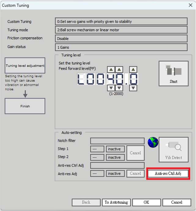
3. If you do not know the vibration frequency, click the Auto Detect Button. If you know the vibration frequency,
click the Manual Set Button.
To Automatically Detect the Vibration Frequency
The frequency will be set.
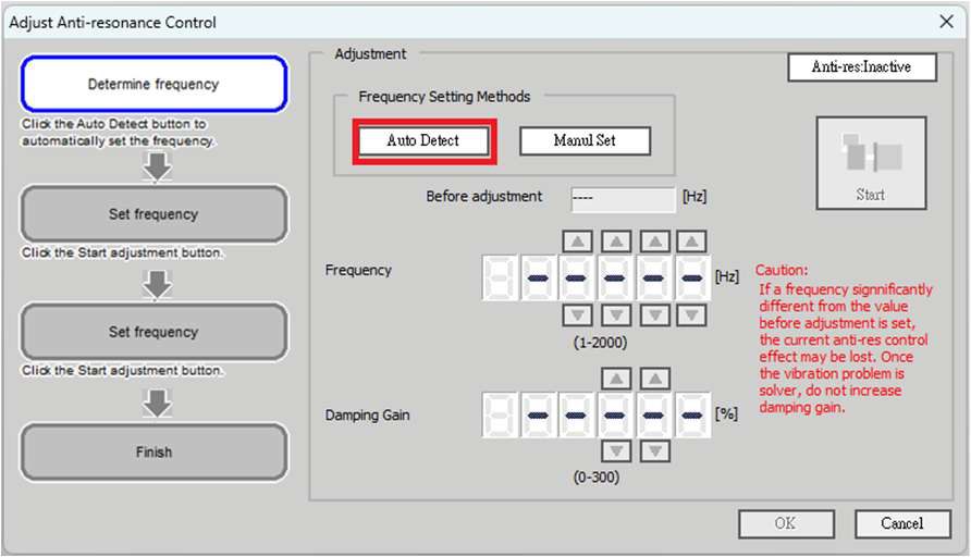
4. Click the Start adjustment Button.
To Manually Set the Vibration Frequency
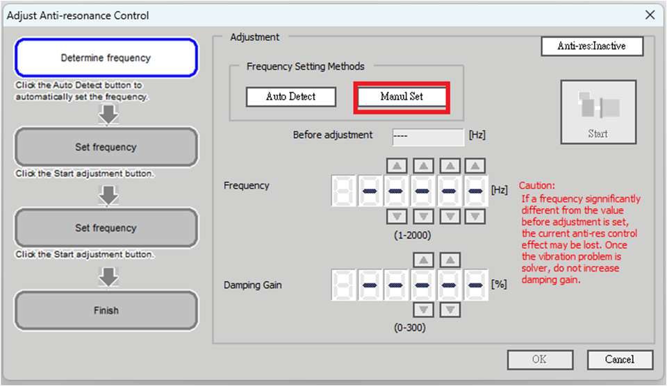
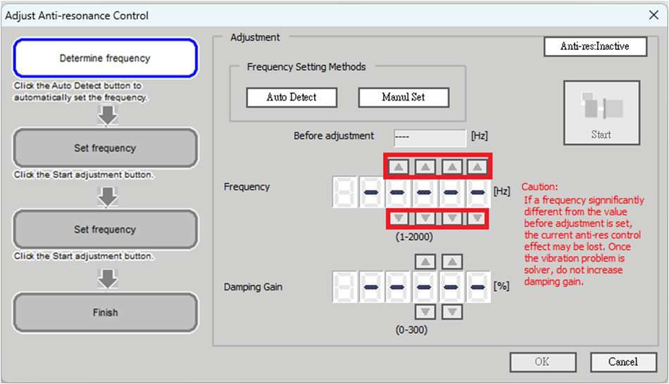
5. Use the [ ▲ ]and [ ▼ ] Buttons in the Adjustment Area to change the settings.
Click the Reset Button during tuning to restore the setting to its original value. The tuning level will return to the value from before when custom tuning was started.
To Automatically Detect the Vibration Frequency To Manually Set the Vibration Frequency
Change the setting of the damping gain. Change the settings of the frequency and damping gain.
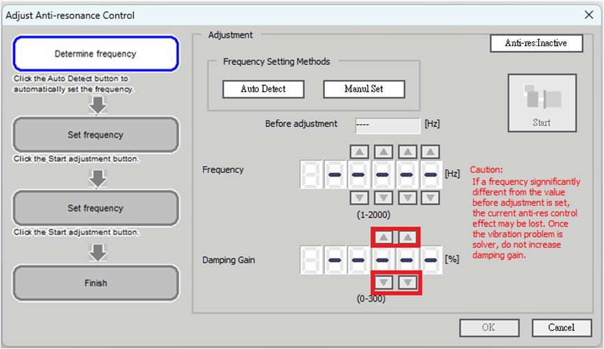
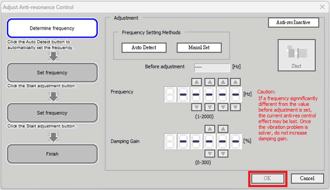
6. When the adjustment has been completed, click the OK Button.
The values that were changed will be saved in the servo driver and you will return to the Tuning Dialog Box.
This concludes the procedure to set up anti-resonance control.
12.9.5 Related Parameters
The following parameters are automatically adjusted or used as reference when you execute anti-resonance control adjustment. Do not change the settings while anti-resonance control adjustment is being executed.
|
Parameter Pn160 |
Name |
Automatic Changes |
|
Anti-Resonance Control-Related Selections |
Yes |
|
|
Pn161 Pn162 |
Anti-Resonance Frequency |
Yes |
|
Anti-Resonance Gain Correction |
No |
|
|
Anti-Resonance Damping Gain |
Yes |
|
|
Anti-Resonance Filter Time Constant 1 Correction |
No |
|
|
Pn165 |
Anti-Resonance Filter Time Constant 2 Correction |
No |
Yes: The parameter is automatically set.
No: The parameter is not automatically set, but the setting is read during execution.





12.10Vibration Suppression
This section describes vibration suppression.
12.10.1 Outline
You can use vibration suppression to suppress transient vibration at a low frequency from 1 Hz to 100 Hz, which is generated mainly when the machine vibrates during positioning. This is effective for vibration frequencies for which notch filters and anti-resonance control adjustment are not effective.
Vibration suppression is automatically set by autotuning without a host reference or autotuning with a host reference. Use vibration suppression only if fine-tuning is required or readjustment is required as a result of a failure to detect vibration.
To execute vibration suppression, input an operation reference and execute the function when there is vibration.
Perform custom tuning if required to increase the response after performing vibration suppression.
CAUTION
Related parameters will be set automatically when vibration suppression is executed. This may greatly affect the response before and after execution. Make sure that you can perform an emergency stop at any time.
Before you execute vibration suppression, set the correct moment of inertia ratio (Pn103) with autotuning without a host reference or another method. If the setting greatly differs from the actual moment of inertia ratio, normal control of the machine may not be possible, and vibration may occur.
|
•Vibration suppression detects vibration frequencies between 1 Hz and 100 Hz. •Frequency detection will not be performed if there is no vibration in the position deviation or if the vibration frequency is outside the range of detectable frequencies. If that is a problem, use a device such as a displacement meter or vibration sensor to measure the vibration frequency. •If an automatically detected vibration frequency is not suppressed, the actual frequency and the detected frequency may be different. Fine-tune the detected frequency if necessary. |
Items That Influence Performance
If continuous vibration occurs while the Servomotor is stopping, vibration suppression cannot be used to suppress the vibration effectively. In this case, use anti-resonance control adjustment or custom tuning.
Detection of Vibration Frequencies
Frequency detection may not be possible if vibration does not appear in the position deviation or the vibration that results from the position deviation is too small. You can adjust the detection sensitivity by changing the setting of the residual vibration detection width (Pn560), which is set as a percentage of the positioning completed width (Pn522). Perform the detection of vibration frequencies again after adjusting the setting of Pn560.
|
Pn560 |
Residual Vibration Detection Width |
Position |
|||||
|
Setting Range |
Setting Unit |
Default Setting |
When Enabled |
Classification |
|||
|
1 ~ 3000 |
0.1% |
400 |
Immediately |
Setup |
|||
NOTE: As a guideline, change the setting 10% at a time. If the setting of this parameter is lowered, the detection sensitivity will be increased.
Vibration may not be detected accurately if the setting is too small.
NOTE:The vibration frequencies that are automatically detected may vary somewhat with each positioning operation. Perform positioning several times and make adjustments while checking the effect of vibration suppression.

12.10.2 Preparations
Always check the following before you execute vibration suppression.
|
• • |
Position control must be used. The tuning-less function must be disabled (Pn170 = n.▯▯▯0). The parameters must not be write prohibited.” |
12.10.3 Applicable Tools
The following table lists the tools that you can use to perform vibration suppression.
|
Tool |
Fn No./Function Name |
Operating Procedure Reference |
|
Panel Operator |
You cannot execute vibration suppression from the Panel Operator. |
|
|
Digital Operator |
Fn205 |
Digital Operator Operating Manual |
|
Protuner |
[Tuning] - [Tuning] |
Operating Procedure |
12.10.4 Operating Procedure
Use the following procedure to perform vibration suppression.
1. Perform steps 1 to 8 of the procedure for custom tuning. Refer to the following section for details. 2. Click the Vib Suppress Button.
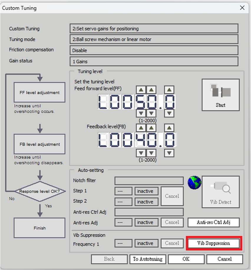
3. Click the Import Button or click [ ▲ ]and [ ▼ ]Button to manually adjust the set frequency.
When you click the Import Button, the residual vibration frequency in the Servomotor is read as the set frequency. (The frequency can be read only when the residual vibration frequency is between 1.0 and 100.0.)
|
Frequency detection will not be performed if there is no vibration or if the vibration frequency is outside the range of detectable frequencies. If a vibration frequency is not detected, provide a means of measuring the vibration frequency. |

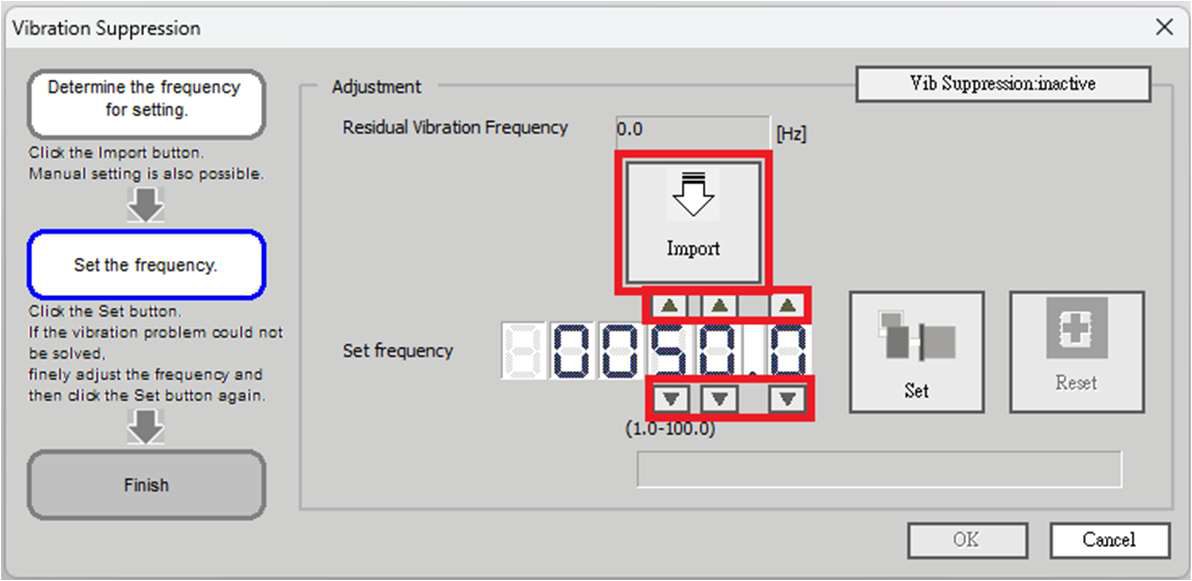
4. Click the Set Button.
|
No settings related to vibration suppression are changed during operation. If the Servomotor does not stop within approximately 10 seconds after changing the setting, an update timeout will occur. The setting will be automatically returned to the previous value. |
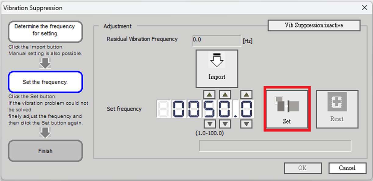
If the vibration is not eliminated, use the [ ▲ ]and [ ▼ ] Buttons for the set frequency to fine-tune thevalue and click
the Set Button again.
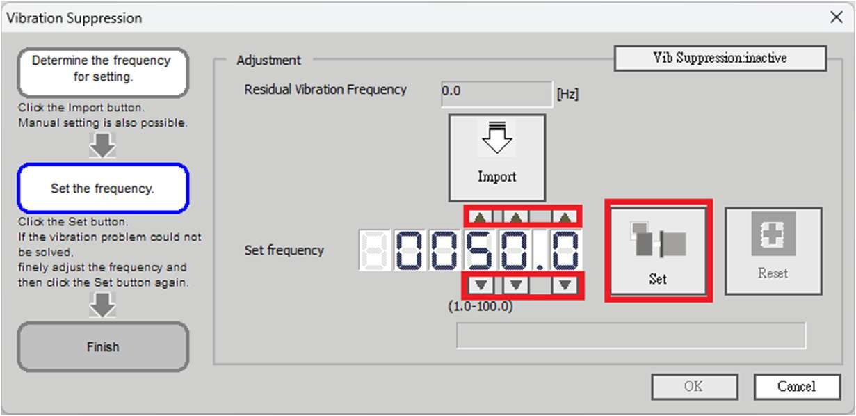
Click the Reset Button during adjustment to restore the setting to its original value. The status from before when
adjustment was started will be restored.
5. When the vibration has been eliminated, click the Finish Button.
The updated value will be saved in the servo driver.

This concludes the procedure to set up vibration suppression.



12.10.5 Setting Combined Functions
You can also use the feedforward function when you execute vibration suppression.
In the default settings, feedforward (Pn109), the speed feedforward input (V-REF), and the torque feedforward input (T-REF) are disabled.
To use the speed feedforward input (V-REF), the torque feedforward input (T-REF), and model following control from the host controller in the system, set Pn140 to n.1 ▯▯▯ (Use model following control and speed/torque feedforward together).
|
Parameter |
Function |
When Enabled |
Classification |
|
|
Pn140 |
n.0▯▯▯ |
Do not use model following control and speed/torque feedforward together. |
Immediately |
Tuning |
|
n.1▯▯▯ |
Use model following control and speed/ torque feedforward together. |
|||
Refer to the following section for information on the torque feedforward input (T-REF) and the speed feedforward input (V-REF).
•
12.10.6 Related Parameters
The following parameters are automatically adjusted or used as reference when you execute vibration suppression.
Do not change the settings while vibration suppression is being executed.
|
Parameter Pn140 |
Name |
Automatic Changes |
|
Model Following Control-Related Selections |
Yes |
|
|
Pn141 Pn142 |
Model Following Control Gain |
Yes |
|
Model Following Control Correction |
No |
|
|
Pn143 |
Model Following Control Bias in the Forward Direction |
No |
|
Pn144 Pn145 |
Model Following Control Bias in the Reverse Direction |
No |
|
Vibration Suppression 1 Frequency A |
Yes |
|
|
Pn146 Pn147 |
Vibration Suppression 1 Frequency B |
Yes |
|
Model Following Control Speed Feedforward Compensation |
No |
|
|
Pn14A |
Vibration Suppression 2 Frequency |
No |
|
Pn14B |
Vibration Suppression 2 Correction |
No |
Yes: The parameter is automatically set.
No: The parameter is not automatically set, but the setting is read during execution.。
12.11Additional Adjustment Functions
This section describes the functions that you can use to make adjustments after you perform autotuning without a host reference, autotuning with a host reference, and custom tuning.
|
Function |
Applicable Control Methods |
|
Gain Switching |
Position control, speed control, or torque control* |
|
Friction Compensation |
Position control or speed control |
|
Current Control Mode Selection |
Position control, speed control, or torque control |
|
Current Gain Level Setting |
Position control or speed control |
|
Speed Detection Method Selection |
Position control, speed control, or torque control |
|
Proportional Control |
Position control or speed control |
* Automatic gain switching is enabled only for position control.
12.11.1 Gain Switching
Two gain switching functions are available, manual selection and automatic switching. The manual switching function uses an external input signal to select the gains, and the automatic.
switching function changes the gains automatically. You can use gain switching to shorten the positioning time by increasing the gains during positioning and suppressing vibration by decreasing the gains while stopping.
|
Parameter |
Function |
When Enabled |
Classification |
|
|
Pn139 |
n.▯▯▯0 |
Use manual gain switching. |
Immediately |
Tuning |
|
n.▯▯▯2 |
Use automatic gain switching pattern 1. |
|||
NOTE: Pn139 = n.▯▯▯1 is a reserved setting. Do not use this setting.
Gain Switching Combinations
|
Selected Gains |
Speed Loop Gain |
Speed Loop Integral Time Constant |
Position Loop Gain |
Torque Reference Filter |
Model |
Model Following Control |
Friction |
|
Gain |
Speed |
Speed Loop Integral Time Constant |
Position Loop Gain (Pn102) |
First Stage First |
Model |
Model |
Friction |
|
Gain |
Second Speed |
Second Speed Loop Integral Time Constant (Pn105) |
Second Position Loop |
First Stage |
Second Model Following |
Second Model Following |
Second |
* Gain switching for the model following control gain and the model following control gain correction is applicable only to manual gain switching. To enable gain switching with these parameters, a gain switching input signal must be used and the following con ditions must be met. If the conditions are not met, these parameters will not be changed even if the other param eters in the above table are changed.
• There must be no reference.
• The motor must be stopped.
Manual Gain Switching
With manual gain switching, you use the /G-SEL (Gain Selection) signal to change between gain settings 1 and gain settings 2.
|
Type |
Signal |
Connector Pin No. |
Setting |
Meaning |
|
Input |
/G-SEL |
Must be allocated. |
OFF |
Changes the gain settings to gain settings 1. |
|
ON |
Changes the gain settings to gain settings 2. |
Automatic Gain Switching
Automatic gain switching is enabled only for position control. The switching conditions are specified by using the following settings.
|
Parameter |
Switching Condition |
Selected Gains |
Switching Waiting Time |
Switching Time |
|
|
Pn139 |
n.▯▯▯2 |
Condition A satisfied |
Gain settings 1 to gain settings 2 |
Gain Switching Waiting Time 1 Pn135 |
Gain |
|
Condition A not satisfied |
Gain settings 2 to gain settings 1 |
Gain Switching Waiting Time 2 Pn136 |
Gain |
||
Select one of the following settings for switching condition A.
|
Parameter |
Position Control Gain Switching Condition A |
For Control Methods Other Than Position Control (No Switching) |
When Enabled |
Classification |
|
|
Pn139 |
n.▯▯0▯ |
/COIN (Positioning |
Gain settings 1 used. |
Immediately |
Tuning |
|
n.▯▯1▯ |
/COIN (Positioning |
Gain settings 2 used. |
|||
|
n.▯▯2▯ |
/NEAR (Near) signal ON |
Gain settings 1 used. |
|||
|
n.▯▯3▯ |
/NEAR (Near) signal OFF |
Gain settings 2 used. |
|||
|
n.▯▯4▯ |
Position reference filter output is 0 and reference pulse input is OFF. |
Gain settings 1 used. |
|||
|
n.▯▯5▯ |
Position reference pulse input is ON. |
Gain settings 2 used. |
|||
Automatic Switching Pattern 1 (Pn139 = n.▯▯▯2)
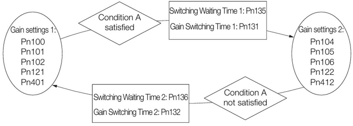
◆Relationship between the Waiting Times and Switching Times for Gain Switching In this example, an ON /COIN (Positioning Completion) signal is set as condition A for automatic gain switching. The position loop gain is changed from the value in Pn102 (Position Loop Gain) to the value in Pn106 (Second Position Loop Gain). When the /COIN signal turns ON, the switching operation begins after the waiting time (Pn135). The switching operation changes the position loop gain linearly from the gain set in Pn102 to the gain set in Pn106 over the switching time (Pn131).
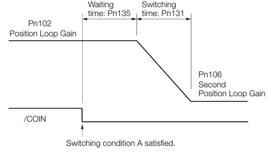
NOTE:You can use gain switching for either PI control or I-P control (Pn10B = n.▯▯0 ▯ or ▯▯1 ▯).
Related Parameters
|
Pn100 |
Speed Loop Gain |
Speed |
Position |
|||||||||
|
Setting Range |
Setting Unit |
Default Setting |
When Enabled |
Classification |
||||||||
|
10 ~ 20000 |
0.1Hz |
400 |
Immediately |
Tuning |
||||||||
|
Pn101 |
Speed Loop Integral Time Constant |
Speed |
Position |
|||||||||
|
Setting Range |
Setting Unit |
Default Setting |
When Enabled |
Classification |
||||||||
|
15 ~ 51200 |
0.01ms |
2000 |
Immediately |
Tuning |
||||||||
|
Pn102 Pn401 |
Position Loop Gain |
Position |
||||||||||
|
Setting Range |
Setting Unit |
Default Setting |
When Enabled |
Classification |
||||||||
|
10 ~ 20000 |
0.1/s |
400 |
Immediately |
Tuning |
||||||||
|
First Stage First Torque Reference Filter Time Constant
|
Speed |
led |
Position |
|||||||||
|
Classification |
||||||||||||
|
0 ~ 65535 |
0.01ms |
100 |
Immediately |
Tuning |
||||||||
|
Pn141 |
Model Following Control Gain |
Position |
||||||||||
|
Setting Range |
Setting Unit |
Default Setting |
When Enabled |
Classification |
||||||||
|
10 ~ 20000 |
0.1/s |
500 |
Immediately |
Tuning |
||||||||
|
Pn142 |
Model Following Control Gain Correction |
Position |
||||||||||
|
Setting Range |
Setting Unit |
Default Setting |
When Enabled |
Classification |
||||||||
|
500 ~ 2000 |
0.1% |
1000 |
Immediately |
Tuning |
||||||||
|
Pn121 |
Friction Compensation Gain |
Speed |
Position |
|||||||||
|
Setting Range |
Setting Unit |
Default Setting |
When Enabled |
Classification |
||||||||
|
10 ~ 1000 |
1% |
100 |
Immediately |
Tuning |
||||||||
|
Pn104 |
Second Speed Loop Gain |
Speed |
Position |
|||||||||
|
Setting Range |
Setting Unit |
Default Setting |
When Enabled |
Classification |
||||||||
|
10 ~ 20000 |
0.1Hz |
400 |
Immediately |
Tuning |
||||||||
|
Pn105 |
Second Speed Loop Integral Time Constant |
Speed |
Position |
|||||||||
|
Setting Range |
Setting Unit |
Default Setting |
When Enabled |
Classification |
||||||||
|
15 ~ 51200 |
0.01ms |
2000 |
Immediately |
Tuning |
||||||||
|
Pn106 Pn412 |
Second Position Loop Gain |
Position |
||||||||||
|
Default Setting |
When Enabled |
Classification |
|||||||||
|
400 |
Immediately |
Tuning |
|||||||||
|
First Stage Second Torque Reference Filter Time Constant
|
Speed |
led |
Position |
|||||||||
|
Classification |
||||||||||||
|
0 ~ 65535 |
0.01ms |
100 |
Immediately |
Tuning |
||||||||
|
Pn148 |
Second Model Following Control Gain |
Position |
||||||||||
|
Setting Range |
Setting Unit |
Default Setting |
When Enabled |
Classification |
||||||||
|
10 ~ 20000 |
0.1/s |
500 |
Immediately |
Tuning |
||||||||
|
Pn149 |
Second Model Following Control Gain Correction |
Position |
||||||||||
|
Setting Range |
Setting Unit |
Default Setting |
When Enabled |
Classification |
||||||||
|
500 ~ 2000 |
0.1% |
1000 |
Immediately |
Tuning |
||||||||
|
Pn122 |
Second Friction Compensation Gain |
Speed |
Position |
|||||||||
|
Setting Range |
Setting Unit |
Default Setting |
When Enabled |
Classification |
||||||||
|
10 ~ 1000 |
1% |
100 |
Immediately |
Tuning |
||||||||
Parameters Related to Automatic Gain Switching
|
Pn131 |
Gain Switching Time 1 |
Position |
|||||
|
Setting Range |
Setting Unit |
Default Setting |
When Enabled |
Classification |
|||
|
0 ~ 65535 |
1ms |
0 |
Immediately |
Tuning |
|||
|
Pn132 |
Gain Switching Time 2 |
Position |
|||||
|
Setting Range |
Setting Unit |
Default Setting |
When Enabled |
Classification |
|||
|
0 ~ 65535 |
1ms |
0 |
Immediately |
Tuning |
|||
|
Pn135 |
Gain Switching Waiting Time 1 |
Position |
|||||
|
Setting Range |
Setting Unit |
Default Setting |
When Enabled |
Classification |
|||
|
0 ~ 65535 |
1ms |
0 |
Immediately |
Tuning |
|||
|
Pn136 |
Gain Switching Waiting Time 2 |
Position |
|||||
|
Setting Range |
Setting Unit |
Default Setting |
When Enabled |
Classification |
|||
|
0 ~ 65535 |
1ms |
0 |
Immediately |
Tuning |
|||
Related Monitoring
• Protuner
You can monitor gain switching with the status monitor or with tracing.
• Analog Monitors
|
Parameter |
Analog Monitor |
Monitor Name |
Output Value |
Description |
|
Pn006 |
n.▯▯0B |
Active Gain Monitor |
1V |
Gain settings 1 are enabled. |
|
2V |
Gain settings 2 are enabled. |
12.11.2 Friction Compensation
Friction compensation is used to compensate for viscous friction fluctuations and regular load fluctuations.
You can automatically adjust friction compensation with autotuning without a host reference, autotuning with a host
reference, or custom tuning, or you can manually adjust it with the following procedure.。
Required Parameter Settings
The following parameter settings are required to use friction compensation.
|
Parameter |
Function |
When Enabled |
Classification |
|
|
Pn408 |
n.0▯▯▯ |
Disable friction compensation. |
Immediately |
Setup |
|
n.1▯▯▯ |
Enable friction compensation. |
|||
|
Pn121 |
Friction Compensation Gain |
Speed |
Position |
||||||
|
Setting Range |
Setting Unit |
Default Setting |
When Enabled |
Classification |
|||||
|
10 ~ 1000 |
1% |
100 |
Immediately |
Tuning |
|||||
|
Pn122 |
Second Friction Compensation Gain |
Speed |
Position |
||||||
|
Setting Range |
Setting Unit |
Default Setting |
When Enabled |
Classification |
|||||
|
10 ~ 1000 |
1% |
100 |
Immediately |
Tuning |
|||||
|
Pn123 |
Friction Compensation Coefficient |
Speed |
Position |
||||||
|
Setting Range |
Setting Unit |
Default Setting |
When Enabled |
Classification |
|||||
|
0 ~ 100 |
1% |
0 |
Immediately |
Tuning |
|||||
|
Pn124 |
Friction Compensation Frequency Correction |
Speed |
Position |
||||||
|
Setting Range |
Setting Unit |
Default Setting |
When Enabled |
Classification |
|||||
|
-10000 ~ 10000 |
0.1Hz |
0 |
Immediately |
Tuning |
|||||
|
Pn125 |
Friction Compensation Gain Correction |
Speed |
Position |
||||||
|
Setting Range |
Setting Unit |
Default Setting |
When Enabled |
Classification |
|||||
|
1 ~ 1000 |
1% |
100 |
Immediately |
Tuning |
|||||




Operating Procedure for Friction Compensation
CAUTION
Before you execute friction compensation, set the moment of inertia ratio (Pn103) as accurately as possible. If the setting greatly differs from the actual moment of inertia, vibration may occur.
|
Step |
Operation |
|
1 |
Set the following parameters related to friction compensation to their default settings. Friction compensation gain (Pn121): 100 |
|
2 |
Gradually increase the friction compensation coefficient (Pn123) to check the effect of friction compensation. NOTE:Usually, set the friction compensation coefficient (Pn123) to 95% or less. If the effect is insufficient, increase the friction compensation gain (Pn121) by 10% increments until vibration stops. Effect of Adjusted Parameters Pn123: Friction Compensation Coefficient This parameter sets the effect of friction compensation. The higher the setting is, the more effective friction compensation will be. If the setting is too high, however, vibration will occur more easily. Usually, set the value to 95% or less. |
|
3 |
Effect of Adjustments
|
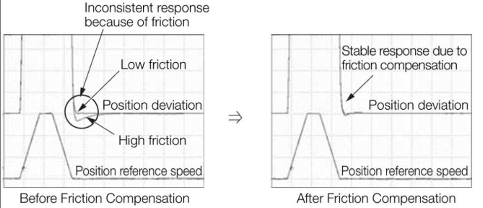
12.11.3 Current Gain Level Setting
You can set the current gain level to reduce noise by adjusting the parameter for current control inside the servo driver according to the speed loop gain (Pn100). The noise level can be reduced by decreasing the current gain level (Pn13D) from its default setting of 2,000% (disabled). However, if the setting is decreased, the level of noise will be lowered, but the response characteristic of the servo driver will also be reduced. Adjust the current gain level within the range that maintains the servo driver response characteristic. This function is always disabled during torque control (Pn000 = n.▯▯2 ▯).
|
Pn13D |
Current Gain Level |
Speed |
Position |
|||||
|
Setting Range |
Setting Unit |
Default Setting |
When Enabled |
Classification |
||||
|
100 ~ 2000 |
1% |
2000 |
Immediately |
Tuning |
||||
|
If the current gain level is changed, the response characteristic of the speed loop will also change. Servo tuning must therefore be performed again. |

12.11.4 Speed Detection Method Selection
You can use the speed detection method selection to ensure smooth Servomotor speed changes during operation. To ensure smooth motor speed changes during operation, set Pn009 to n.▯1 ▯▯ (Use speed detection 2).
With a Linear Servomotor, you can reduce the noise level of the running motor when the linear encoder scale pitch is large.。
|
Parameter |
Meaning |
When Enabled |
Classification |
|
|
Pn009 |
n.▯0▯▯ |
Use speed detection 1. |
After restart |
Tuning |
|
n.▯1▯▯ |
Use speed detection 2. |
|||
|
If the speed detection method is changed, the response characteristic of the speed loop will also change. Servo tuning must therefore be performed again. |
12.11.5 Speed Feedback Filter
You can set a first order lag filter for the speed feedback in the speed loop. This ensures smooth changes in the feedback speed to reduce vibration. If a large value is set, it will increase the delay and make response slower.
|
Pn308 |
Speed Feedback Filter Time Constant |
Speed |
Position |
|||||
|
Setting Range |
Setting Unit |
Default Setting |
When Enabled |
Classification |
||||
|
0 ~ 65535 |
0.01ms |
0 |
Immediately |
Setup |
||||
12.11.6 Proportional Control (P Control)
You can input the /P-CON (Proportional Control) signal from the host controller to select P control.
The speed control section uses proportional-integral control (PI control) if the reference remains at zero during speed control. The integral effect may cause the Servomotor to move. To prevent that, you can change from PI control to P control.
P control is set using Pn000 = n.▯▯X ▯ and the /P-CON signal.
However, if Pn000 is set to n.▯▯A ▯ (Switching between speed control with analog references and speed control with zero clamping), a position loop will be formed. Therefore, there is no need to use this function.
P control is used while the /P-CON signal is ON.
/P-CON (Proportional Control) Signal
The /P-CON signal is used to switch between P control and PI control.
|
Type |
Signal |
Connector Pin No. |
Setting |
Meaning |
|
Input |
/P-CON |
CN1-41 |
ON (closed) |
Changes to P control |
|
OFF (open) |
Changes to PI control |
When Using the Default Input Signal Allocations
servo driver
CN1
/P-CON 41
Changing between P and PI control
NOTE:This example uses the default input signal allocations.
Control Methods and P Control Input Signals
Changing to P control is enabled when the control method is set to speed control or position control.
|
Parameter |
Control Method Selection |
Description |
Changing to |
|
Pn000 |
n.▯▯0▯ |
Speed control with analog references |
You can change to You can also allocate the /P-CON signal to another connector |
|
n.▯▯1▯ |
Position control with pulse train references |
||
|
n.▯▯2▯ |
Torque control with analog references |
You cannot change to P control. |
|
|
n.▯▯3▯ |
Internal set speed control with contact commands |
You must allocate the /P-CON signal to |
|
|
n.▯▯4▯ |
Switching between internal set speed control with contact commands and speed control with analog references |
||
|
n.▯▯5▯ |
Switching between internal set speed control with contact commands and position control with pulse train references |
||
|
n.▯▯6▯ |
Switching between internal set speed control with contact commands and torque control with analog references |
||
|
n.▯▯7▯ |
Switching between position control with pulse train references and speed control with analog references |
||
|
n.▯▯8▯ |
Switching between position control with pulse train references and torque control with analog references |
||
|
n.▯▯9▯ |
Switching between torque control with analog references and speed control with analog references |
||
|
n.▯▯A▯ |
Switching between speed control with analog references and speed control with zero clamping |
||
|
n.▯▯B▯ |
Switching between position control with pulse train references and position control with reference pulse inhibition |
NOTE: Refer to the following section for information on changing the control method.
12.12 Manual Tuning
This section describes manual tuning.
12.12.1 Tuning the Servo Gains
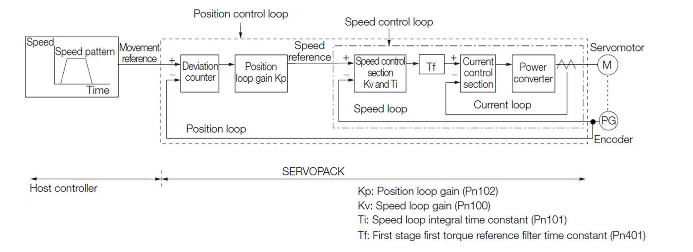
In order to manually tune the servo gains, you must understand the configuration and characteristic of the servo driver and adjust the servo gains individually. In most cases, if you greatly change any one parameter, you must adjust the other parameters again. To check the response characteristic, you must prepare a measuring instrument to monitor the output waveforms from the analog monitor.
The Servo Driver has three feedback systems (the position loop, speed loop, and current loop), and the response characteristic must be increased more with the inner loops. If this relationship is not maintained, the response characteristic will suffer and vibration will occur more easily.
A sufficient response characteristic is ensured for the current loop. There is never a need for it to be adjusted by the user.
Outline
You can use manual tuning to set the servo gains in the servo driver to increase the response characteristic of the servo driver. For example, you can reduce the positioning time for position control.
Use manual tuning in the following cases.
• When tuning with autotuning without a host reference or autotuning with a host reference does not achieve the • desired results
• When you want to increase the servo gains higher than the gains that resulted from autotuning without a host • reference or autotuning with a host reference
• When you want to determine the servo gains and moment of inertia ratio yourself
You start manual tuning either from the default parameter settings or from the gain settings that resulted from autotuning without a host reference or autotuning with a host reference.
Applicable Tools
You can monitor the servo gains with the Protuner or with the analog monitor.
Precautions
Vibration may occur while you are tuning the servo gains. We recommend that you enable vibration alarms (Pn310 = n.▯▯▯2) to detect vibration. Refer to the following section for information on vibration detection.
Tuning Procedure Example (for Position Control or Speed Control)
|
Step |
Description |
|
1 |
Adjust the first stage first torque reference filter time constant (Pn401) so that vibration does not occur. |
|
2 |
Increase the Speed loop gain (Pn100) and reduce the speed loop integral time constant (Pn101) as far as possible within the range that does not cause machine vibration. |
|
3 |
Repeat steps 1 and 2 and return the settings about 10% to 20% from the values that you set. |
|
4 |
For position control, increase the position loop gain (Pn102) within the range that does not cause vibration. |
NOTE: If you greatly change any one servo gain parameter, you must adjust the other parameters again. Do not increase the setting of just one parameter. As a guideline, adjust the settings of the servo gains by approximately 5% each. As a rule, change the servo parameters in the following order.。
• To Increase the Response Speed
1. Reduce the torque reference filter time constant.
2. Increase the speed loop gain.
3. Decrease the speed loop integral time constant.
4. Increase the position loop gain.
• To Reduce Response Speed and to Stop Vibration and Overshooting
1. Reduce the position loop gain.
2. Increase the speed loop integral time constant.
3. Decrease the speed loop gain.
4. Increase the torque filter time constant.
Adjusted Servo Gains
You can set the following gains to adjust the response characteristic of the Servo Driver.
• Pn100:Speed Loop Gain
• Pn101:Speed Loop Integral Time Constant
• Pn102:Position Loop Gain
• Pn401:First Stage First Torque Reference Filter Time Constant
◆ Position Loop Gain
The position loop gain determines the response characteristic of the position loop in the Servo Driver. If you can increase the setting of the position loop gain, the response characteristic will improve and the positioning time will be shortened. However, you normally cannot increase the position loop gain higher than the inherit vibration frequency of the machine system. Therefore, to increase the setting of the position loop gain, you must increase the rigidity of the machine to increase the inherit vibration frequency of the machine.
|
Pn102 |
Position Loop Gain |
Position |
|||||
|
Setting Range |
Setting Unit |
Default Setting |
When Enabled |
Classification |
|||
|
10 ~ 20000 |
0.1/s |
400 |
Immediately |
Tuning |
|||
NOTE:For machines for which a high position loop gain (Pn102) cannot be set, overflow alarms can occur during high-speed operation. If that is the case, you can increase the setting of the following parameter to increase the level for alarm detection.
Use the following condition as a guideline for determining the setting.
Pn520 ≧ Maximum feed speed [reference units/s] × 2.0
Pn102÷10(1/s)
If you use a position reference filter, transient deviation will increase due to the filter time constant. When you
make the setting, consider deviation accumulation that may result from the filter.。
|
Pn520 |
Position Deviation Overflow Alarm Level |
Position |
|||||
|
Setting Range |
Setting Unit |
Default Setting |
When Enabled |
Classification |
|||
|
1 ~ 1073741823 |
1 reference unit |
5242880 |
Immediately |
Setup |
|||
◆ Speed Loop Gain
This parameter determines the response characteristic of the speed loop. If the response characteristic of the speed loop is low, it becomes a delay factor for the position loop located outside of the speed loop. This will result in overshooting and vibration in the speed reference.
Therefore, setting the speed loop gain as high as possible within the range that will not cause the machine system to vibrate will produce a stable servo system with a good response characteristic.
|
Pn100 |
Speed Loop Gain
|
Speed n Enable |
d |
P |
osition |
s |
Torque |
|||||||
|
Classification |
||||||||||||||
|
10 ~ 20000 |
0.1Hz |
400 |
Immediately |
Tuning |
||||||||||

The default setting of Pn103 (Moment of Inertia Ratio) is 100. Before you tune the servo, calculate the moment of inertia ratio with the above formula and set Pn103 to the calculation result.
|
Pn103 |
Moment of Inertia Ratio
|
Speed n Enable |
d |
P |
osition |
s |
Torque |
|||||||
|
Classification |
||||||||||||||
|
0 ~ 20000 |
1% |
100 |
Immediately |
Tuning |
||||||||||
|
◆ |
Speed Loop Integral Time Constant |
To enable response to even small inputs, the speed loop has an integral element. The integral element becomes a delay factor in the servo system. If the time constant is set too high, overshooting will occur, positioning settling time will increase, and the response characteristic will suffer.
|
Pn101 |
Speed Loop Integral Time Constant |
Speed |
Position |
||||||
|
Setting Range |
Setting Unit |
Default Setting |
When Enabled |
Classification |
|||||
|
15 ~ 51200 |
0.01ms |
2000 |
Immediately |
Tuning |
|||||
|
◆ |
Torque Reference Filter |
As shown in the following diagram, the torque reference filter contains a first order lag filter and notch filters
arranged in series, and each filter operates independently.
The notch filters can be enabled and disabled with Pn408 = n.▯X▯X and Pn416 = n.▯XXX.
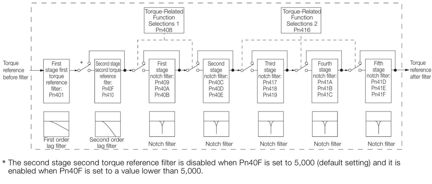
Torque Reference Filter
If you suspect that machine vibration is being caused by the Servo Drive, try adjusting the torque reference filter time constant. This may stop the vibration. The lower the value, the better the control response characteristic will be, but there may be a limit depending on the machine conditions.
|
Pn401 Pn40F |
First Stage First Torque Reference Filter Time Constant
|
Speed |
d |
P |
osition
sification |
||||||||||
|
0 ~ 65535 |
0.01ms |
100 |
Immediately |
osition |
|||||||||||
|
Second Stage Second Torque Reference Filter Frequency
|
Speed |
d |
P |
||||||||||||
|
Classification |
|||||||||||||||
|
100 ~ 5000 |
1Hz |
5000* |
Immediately |
Tuning |
|||||||||||
|
Pn410 |
Second Stage Second Torque Reference Filter Q Value
|
Speed |
d |
P |
osition |
Torque |
|||||||||
|
Classification |
|||||||||||||||
|
50 ~ 100 |
0.01 |
50 |
Immediately |
Tuning |
|||||||||||
* The filter is disabled if you set the parameter to 5,000.
Notch Filters
The notch filter can eliminate specific frequency elements generated by the vibration of sources such as resonance of the shaft of a ball screw.
The notch filter puts a notch in the gain curve at the specific vibration frequency (called the notch frequency). The frequency components near the notch frequency can be reduced or removed with a notch filter.
Notch filters are set with three parameters for the notch filter frequency, notch filter Q value, and notch filter depth. This section describes the notch filter Q value and notch filter depth.
Notch filter Q Value
The setting of the notch filter Q value determines the width of the frequencies that are filtered for the notch filter frequency. The width of the notch changes with the notch filter Q value. The larger the notch filter Q value is, the steeper the notch is and the narrower the width of frequencies that are filtered is.
The notch filter frequency characteristics for different notch filter Q values are shown below.
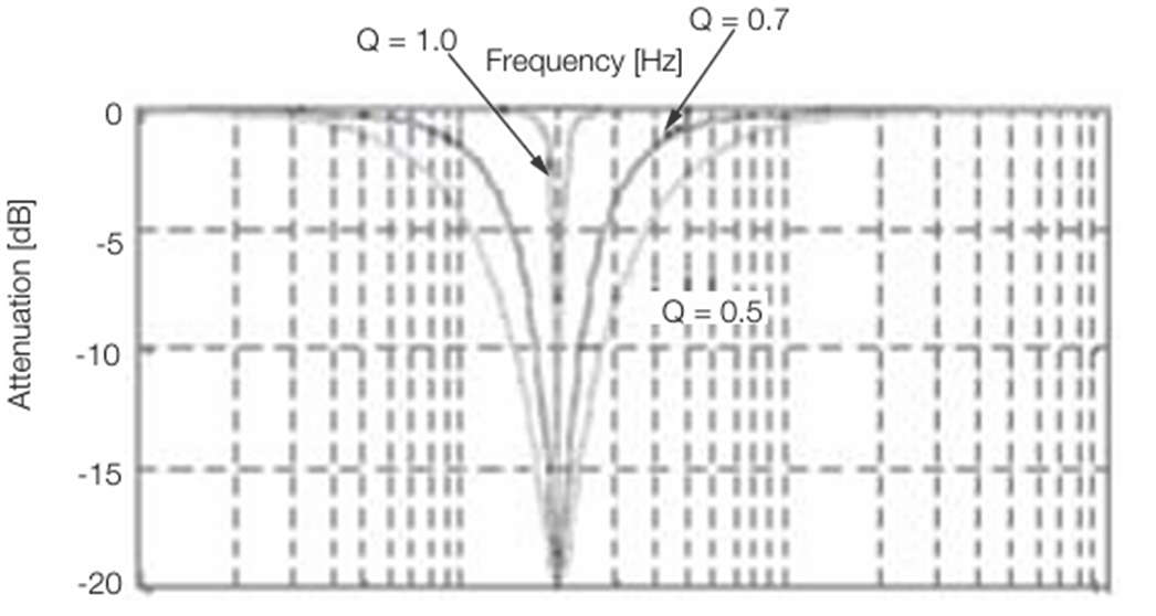
Notch Filter Depth
The setting of the notch filter depth determines the depth of the frequencies that are filtered for the notch
filter frequency. The depth of the notch changes with the notch filter depth. The smaller the notch filter depth is, the deeper the notch is, increasing the effect of vibration suppression. However, if the value is too small, vibration can actually increase.
The notch filter is disabled if the notch filter depth, d, is set to 1.0 (i.e., if Pn419 is set to 1,000).
The notch filter frequency characteristics for different notch filter depths are shown below.
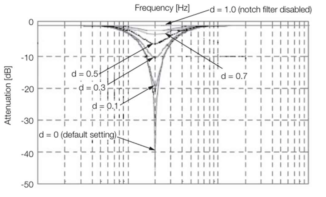
You can enable or disable the notch filter with Pn408 and Pn416.
|
Parameter |
Meaning |
When Enabled |
Classification |
n.▯▯▯0
[default setting ]Disable first stage notch filter.
|
Pn408 |
n.▯▯▯1 |
Enable first stage notch filter. |
||
|
n.▯0▯▯ |
||||
|
n.▯1▯▯ |
Enable second stage notch filter. |
|||
|
n.▯▯▯0 |
Immediately |
Setup |
||
|
Pn41F |
n.▯▯▯1 |
Enable third stage notch filter. |
||
|
n.▯▯0▯ |
||||
|
n.▯▯1▯ |
Enable fourth stage notch filter. |
|||
n.▯0▯▯
[default setting ]Disable fifth stage notch filter.
|
n.▯1▯▯ |
Enable fifth stage notch filter. |
Set the machine vibration frequencies in the notch filter parameters.
|
First Stage Notch Filter Frequency |
Speed |
PositionTorque |
|||
|
Pn409 |
Setting Range |
Setting Unit |
Default Setting |
When Enabled |
Classification |
|
50 ~ 5000 |
1Hz |
5000 |
Immediately |
Tuning |
|
|
First Stage Notch Filter Q Value |
Speed |
PositionTorque |
|||
|
Pn40A |
Setting Range |
Setting Unit |
Default Setting |
When Enabled |
Classification |
|
50 ~ 1000 |
0.01 |
70 |
Immediately |
Tuning |
|
|
First Stage Notch Filter Depth |
Speed |
PositionTorque |
|||
|
Pn40B |
Setting Range |
Setting Unit |
Default Setting |
When Enabled |
Classification |
|
0 ~ 1000 |
0.001 |
0 |
Immediately |
Tuning |
|
|
Second Stage Notch Filter Frequency |
Speed |
PositionTorque |
|||
|
Pn40C |
Setting Range |
Setting Unit |
Default Setting |
When Enabled |
Classification |
|
50 ~ 5000 |
1Hz |
5000 |
Immediately |
Tuning |
|
|
Second Stage Notch Filter Q Value |
Speed |
PositionTorque |
|||
|
Pn40D |
Setting Range |
Setting Unit |
Default Setting |
When Enabled |
Classification |
|
50 ~ 1000 |
0.01 |
70 |
Immediately |
Tuning |
|
|
Second Stage Notch Filter Depth |
Speed |
PositionTorque |
|||
|
Pn40E |
Setting Range |
Setting Unit |
Default Setting |
When Enabled |
Classification |
|
0 ~ 1000 |
0.001 |
0 |
Immediately |
Tuning |
|
|
Third Stage Notch Filter Frequency |
Speed |
PositionTorque |
|||
|
Pn417 |
Setting Range |
Setting Unit |
Default Setting |
When Enabled |
Classification |
|
50 ~ 5000 |
1Hz |
5000 |
Immediately |
Tuning |
|
|
Third Stage Notch Filter Q Value |
Speed |
PositionTorque |
|||
|
Pn418 |
Setting Range |
Setting Unit |
Default Setting |
When Enabled |
Classification |
|
50 ~ 1000 |
0.01 |
70 |
Immediately |
Tuning |
|
|
Third Stage Notch Filter Depth |
Speed |
PositionTorque |
|||
|
Pn419 |
Setting Range |
Setting Unit |
Default Setting |
When Enabled |
Classification |
|
0 ~ 1000 |
0.001 |
0 |
Immediately |
Tuning |
|
|
Fourth Stage Notch Filter Frequency |
Speed |
PositionTorque |
|||
|
Pn41A |
Setting Range |
Setting Unit |
Default Setting |
When Enabled |
Classification |
|
50 ~ 5000 |
1Hz |
5000 |
Immediately |
Tuning |
|
|
Fourth Stage Notch Filter Q Value |
Speed |
PositionTorque |
|||
|
Pn41B |
Setting Range |
Setting Unit |
Default Setting |
When Enabled |
Classification |
|
50 ~ 1000 |
0.01 |
70 |
Immediately |
Tuning |
|
|
Fourth Stage Notch Filter Depth |
Speed |
PositionTorque |
|||
|
Pn41C |
Setting Range |
Setting Unit |
Default Setting |
When Enabled |
Classification |
|
0 ~ 1000 |
0.001 |
0 |
Immediately |
Tuning |
|


|
Pn41D Pn41E Pn41F |
Fifth Stage Notch Filter Frequency
|
Speed |
Position
ication |
|||||||||||
|
50 ~ 5000 |
1Hz |
5000 |
Immediately |
Tuning |
||||||||||
|
Fifth Stage Notch Filter Q Value
|
Speed |
Position |
||||||||||||
|
Classification |
||||||||||||||
|
50 ~ 1000 |
0.01 |
70 |
Immediately |
Tuning |
||||||||||
|
Fifth Stage Notch Filter Depth
|
Speed |
Position |
||||||||||||
|
Classification |
||||||||||||||
|
0 ~ 1000 |
0.001 |
0 |
Immediately |
Tuning |
||||||||||
|
•Do not set notch filter frequencies (Pn409, Pn40C, Pn417, Pn41A, and Pn41D) that are close to the speed loop’s response frequency. Set a frequency that is at least four times the speed loop gain (Pn100). (However, Pn103 (Moment of Inertia Ratio) must be set correctly. If the setting is not correct, vibration may occur and the machine may be damaged. •Change the notch filter frequencies (Pn409, Pn40C, Pn417, Pn41A, and Pn41D) only while the Servomotor is stopped. Vibration may occur if a notch filter frequency is changed during operation. |
Guidelines for Manually Tuning Servo Gains
When you manually adjust the parameters, make sure that you completely understand the information in the product manual and use the following conditional expressions as guidelines. The appropriate values of the parameter settings are influenced by the machine specifications, so they cannot be determined universally. When you adjust the parameters, actually operate the machine and use the Protuner or analog monitor to monitor operating conditions. Even if the status is stable while the Servomotor is stopped, an unstable condition may occur when an operation reference is input. Therefore, input operation references and adjust the servo gains as you operate the Servomotor.
Stable gain: Settings that provide a good balance between parameters.
However, if the load moment of inertia is large and the machine system contains elements prone to vibration, you must sometimes use a setting that is somewhat higher to prevent the machine from vibrating.。
Critical gain: Settings for which the parameters affect each other。
Depending on the machine conditions, overshooting and vibration may occur and operation may not be stable. If the critical gain condition expressions are not met, operation will become more unstable, and there is a risk of abnormal motor shaft vibration and round-trip operation with a large amplitude. Always stay within the critical gain conditions.
If you use the torque reference filter, second torque reference filter, and notch filters together, the interference between the filters and the speed loop gain will be superimposed. Allow leeway in the adjustments.。
|
◆ |
When Pn10B = n.▯▯0▯ (PI Control) |
|
The following adjusted value guidelines require that the setting of Pn103 (Moment of Inertia Ratio) is correctly set for the actual machine. |
Guidelines are given below for gain settings 1.
The same guidelines apply to gain settings 2 (Pn104, Pn105, Pn106, and Pn412).。
• Speed Loop Gain (Pn100 [Hz]) and Position Loop Gain (Pn102 [/s])
Stable gain: Pn102 [/s] ≤ 2π × Pn100/4 [Hz]
Critical gain: Pn102 [/s] < 2π × Pn100 [Hz]
• Speed Loop Gain (Pn100 [Hz]) and Speed Loop Integral Time Constant (Pn101 [ms])
Stable gain: Pn101 [ms] ≥ 4,000/(2π × Pn100 [Hz])
Critical gain: Pn101 [ms] > 1,000/(2π × Pn100 [Hz])
• Speed Loop Gain (Pn100 [Hz]) and First Stage First Torque Reference Filter Time Constant (Pn401 [ms])
Stable gain: Pn401 [ms] ≤ 1,000/(2π × Pn100 [Hz] × 4)
Critical gain: Pn401 [ms] < 1,000/(2π × Pn100 [Hz] × 1)
• Speed Loop Gain (Pn100 [Hz]) and Second Stage Second Torque Reference Filter Frequency (Pn40F [Hz]) Critical gain: Pn40F [Hz] > 4 × Pn100 [Hz]
NOTE: Set the Second Stage Second Torque Reference Filter Q Value (Pn410) to 0.70.
• Speed Loop Gain (Pn100 [Hz]) and First Stage Notch Filter Frequency (Pn409 [Hz]) (or Second Stage Notch Filter Frequency (Pn40C [Hz]))
Critical gain: Pn409 [Hz] > 4 × Pn100 [Hz]
• Speed Loop Gain (Pn100 [Hz]) and Speed Feedback Filter Time Constant (Pn308 [ms]) Stable gain: Pn308 [ms] ≤ 1,000/(2π × Pn100 [Hz] × 4)
Critical gain: Pn308 [ms] < 1,000/(2π × Pn100 [Hz] × 1)
◆ When Pn10B = n.▯▯1▯ (I-P Control)
Guidelines are given below for gain settings 1.
The same guidelines apply to gain settings 2 (Pn104, Pn105, Pn106, and Pn412).
For I-P control, the relationships between the speed loop integral time constant, speed loop gain, and position loop gain are different from the relationships for PI control. The relationship between other servo gains is the same as for PI control.
• Speed Loop Gain (Pn100 [Hz]) and Speed Loop Integral Time Constant (Pn101 [ms]) Stable gain: Pn100 [Hz] ≥ 320/Pn101 [ms]
• Position Loop Gain (Pn102 [/s]) and Speed Loop Integral Time Constant (Pn101 [ms]) Stable gain: Pn102 [/s] ≤ 320/Pn101 [ms]
NOTE: Selecting the Speed Loop Control Method (PI Control or I-P Control)Usually, I-P control is effective for high-speed positioning and high-speed, high-precision processing applications. With I-P control, you can use a lower position loop gain than for PI control to reduce the positioning time and reduce arc radius reduction. However, if you can use mode switching to change to proportional control to achieve the desired application, then using PI control would be the normal choice.
◆ Decimal Points in Parameter Settings
For the SC3 servo drivers, decimal places are given for the settings of parameters on the Digital Operator,
Panel Operator, and in the manual. For example with Pn100 (Speed Loop Gain), Pn100 = 40.0 is used to indicate
a setting of 40.0 Hz. In the following adjusted value guidelines, the decimal places are also given.
• Speed Loop Gain (Pn100 [Hz]) and Speed Loop Integral Time Constant (Pn101 [ms])
Stable gain: Pn101 [ms] ≥ 4,000/(2π × Pn100 [Hz]), therefore If Pn100 = 40.0 [Hz], then Pn101 = 4,000/(2π × 40.0) ≈ 15.92 [ms].)


Model Following Control
You can use model following control to improve response characteristic and shorten positioning time. You can
use model following control only with position control. Normally, the parameters that are used for model following control are automatically set along with the servo gains by executing autotuning or custom tuning. However, you
must adjust them manually in the following cases.
• When the tuning results for autotuning or custom tuning are not acceptable
• When you want to increase the response characteristic higher than that achieved by the tuning results for autotuning or custom tuning
• When you want to determine the servo gains and model following control parameters yourself
The block diagram for model following control is provided below.
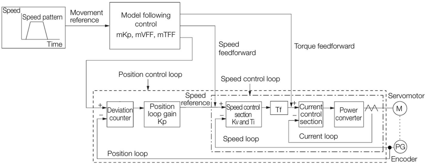
ServoDriver

◆ Manual Tuning Procedure
Use the following tuning procedure for using model following control.
|
Step |
Description |
|
1 |
Friction compensation must also be used. Set the friction compensation parameters. Refer to the following section for the setting procedure. |
|
2 |
Adjust the servo gains. Refer to the following section for an example procedure. NOTE: 1. Set the moment of inertia ratio (Pn103) as accurately as possible. 2. Refer to the guidelines for manually tuning the servo gains and set a stable gain for the position loop gain (Pn102). |
|
3 |
Increase the model following control gain (Pn141) as much as possible within the range in which overshooting and vibration do not occur. |
|
4 |
If overshooting occurs or if the response is different for forward and reverse operation, fine-tune model following control with the following settings: model following control bias in the forward direction (Pn143), model following control bias in the reverse direction (Pn144), and model following control speed feedforward compensation (Pn147). |
◆ Related Parameters
Next we will describe the following parameters that are used for model following control.
• Pn140 (Model Following Control-Related Selections)
• Pn141 (Model Following Control Gain)
• Pn143 (Model Following Control Bias in the Forward Direction) • Pn144 (Model Following Control Bias in the Reverse Direction)
• Pn147 (Model Following Control Speed Feedforward Compensation)
Model Following Control-Related Selections
Set Pn140 = n.▯▯▯X to specify whether to use model following control.
If you use model following control with vibration suppression, set Pn140 to n.▯▯1 ▯ or Pn140 = n.▯▯2 ▯. When you also perform vibration suppression, adjust vibration suppression with custom tuning in advance.
NOTE: If you use vibration suppression (Pn140 = n.▯▯1 ▯ or Pn140 = n.▯▯2 ▯), always set Pn140 to n.▯▯▯1 (Use model following control).
|
Parameter |
Function |
When Enabled |
Classification |
|
|
Pn140 |
n.▯▯▯0 |
Do not use model following control. |
Immediately |
Tuning |
|
n.▯▯▯1 |
Use model following control. |
|||
|
n.▯▯0▯ |
Do not perform vibration suppression. |
|||
|
n.▯▯1▯ |
Perform vibration suppression for a specific frequency. |
|||
|
n.▯▯2▯ |
Perform vibration suppression for two specific frequencies. |
|||
Model Following Control Gain
The model following control gain determines the response characteristic of the servo system. If you increase the setting of the model following control gain, the response characteristic will improve and the positioning time will be shortened. The response characteristic of the servo system is determined by this parameter, and not by Pn102 (Position Loop Gain).
|
Pn141 |
Model Following Control Gain |
Position |
|||||
|
Setting Range |
Setting Unit |
Default Setting |
When Enabled |
Classification |
|||
|
10 ~ 20000 |
0.1/s |
500 |
Immediately |
Tuning |
|||
NOTE: For machines for which a high model following control gain cannot be set, the size of the position deviation in model following control will be determined by the setting of the model following control gain. For a machine with low rigidity, in which a high model following control gain cannot be set, position deviation overflow alarms may occur during high-speed operation. If that is the case, you can increase the setting of the following parameter to increase the level for alarm detection.
Use the following conditional expression for reference in determining the setting.

|
Pn520 |
Position Deviation Overflow Alarm Level |
Position |
|||||
|
Setting Range |
Setting Unit |
Default Setting |
When Enabled |
Classification |
|||
|
1 ~ 1073741823 |
1 reference unit |
5242880 |
Immediately |
Tuning |
|||
Model Following Control Bias in the Forward Direction and Model Following Control Bias in the
Reverse Direction
If the response is different for forward and reverse operation, use the following parameters for fine-tuning.
If you decrease the settings, the response characteristic will be lowered but overshooting will be less likely to occur.
|
Pn143 |
Model Following Control Bias in the Forward Direction |
Position |
|||||
|
Setting Range |
Setting Unit |
Default Setting |
When Enabled |
Classification |
|||
|
0 ~ 10000 |
0.1% |
1000 |
Immediately |
Tuning |
|||
|
Pn144 |
Model Following Control Bias in the Reverse Direction |
Position |
|||||
|
Setting Range |
Setting Unit |
Default Setting |
When Enabled |
Classification |
|||
|
0 ~ 10000 |
0.1% |
1000 |
Immediately |
Tuning |
|||
Model Following Control Speed Feedforward Compensation
If overshooting occurs even after you adjust the model following control gain, model following control bias in
the forward direction, and model following control bias in the reverse direction, you may be able to improve
performance by setting the following parameter.
If you decrease the settings, the response characteristic will be lowered but overshooting will be less likely to occur.
|
Pn147 |
Model Following Control Speed Feedforward Compensation |
Position |
|||||
|
Setting Range |
Setting Unit |
Default Setting |
When Enabled |
Classification |
|||
|
0 ~ 10000 |
0.1% |
1000 |
Immediately |
Tuning |
|||
Model Following Control Type Selection
When you enable model following control, you can select the model following control type. Normally, set Pn14F to n.▯▯▯1 (Use model following control type 2) (default setting). If compatibility with previous models is required, set Pn14F to n.▯▯▯0 (Use model following control type 1).
|
Parameter |
Meaning |
When Enabled |
Classification |
|
|
Pn14F |
n.▯▯▯0 |
Use model following control type 1. |
After restart |
Tuning |
|
n.▯▯▯0 |
Use model following control type 2. |
|||
12.12.2 Compatible Adjustment Functions
The compatible adjustment functions are used together with manual tuning. You can use these functions to improve adjustment results. These functions allow you to use the same functions as for SC3-Series servo drivers
to adjustSC3-Series servo drivers.。
Feedforward
The feedforward function applies feedforward compensation to position control to shorten the positioning time.
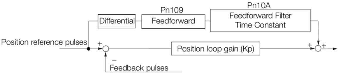
|
Pn109 |
Feedforward |
Position |
|||||
|
Setting Range |
Setting Unit |
Default Setting |
When Enabled |
Classification |
|||
|
0 ~ 100 |
1% |
0 |
Immediately |
Tuning |
|||
|
Pn10A |
Feedforward Filter Time Constant |
Position |
|||||
|
Setting Range |
Setting Unit |
Default Setting |
When Enabled |
Classification |
|||
|
0 ~ 6400 |
0.01ms |
0 |
Immediately |
Tuning |
|||
NOTE: If you set the feedforward value too high, the machine may vibrate. As a guideline, use a setting of 80% or less.。
Torque Feedforward and Speed Feedforward
You can use the torque feedforward and speed feedforward functions to help shorten the positioning time. The
reference is created from the differential of the position reference at the host controller.
Torque feedforward:This is effective for speed control or position control. It is sent from the host controller along with the speed reference. Connect the speed reference from the host controller to the V-REF (CN1-5 and CN1-6) signal and the torque feedforward reference from the host controller to the T-REF (CN1- 9 and CN1-10) signal.
Speed feedforward: This is effective only for position control. It is sent to the servo driver from the host controller along with the position reference. Connect the position reference from the host controller to the PULS and SIGN (CN1-7,CN1 -8, CN1-11, and CN1-12) signals and the speed feedforward reference from the host controller to the V-REF (CN1-5 and CN1-6) signal.
◆ Examples of Connections to Host Controllers
When servo driver Performs Speed Control
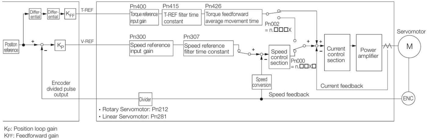
When servo driver Performs Position Contro
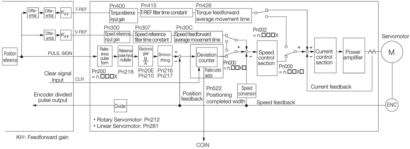
■ Related Parameters
Torque feedforward is allocated to T-REF (Pn002 = n.▯▯▯X) and it is set using the torque reference input gain
(Pn400) and T-REF filter time constant (Pn415).
The default setting of Pn400 is 30. Therefore, if the torque feedforward value is ±3 V, then the torque is limited
to ±100% of the rated torque.
|
Parameter |
Meaning |
When Enabled |
Classification |
|
|
Pn002 |
n.▯▯▯0 |
Do not use T-REF. |
After restart |
Setup |
|
n.▯▯▯1 |
Use T-REF as an external torque limit input. |
|||
|
n.▯▯▯2 |
Use T-REF as a torque feedback input. |
|||
|
n.▯▯▯3 |
Use T-REF as an external torque limit input when /P-CL or /N-CL is active. |
|||
|
Pn400 Pn415 |
Torque Reference Input Gain
|
Speed |
d |
Po |
sition
sification |
||||||||||
|
10 ~ 100 |
0.1 V/rated torque |
30 |
Immediately |
sition |
|||||||||||
|
T-REF Filter Time Constant
|
Speed |
d |
Po |
||||||||||||
|
Classification |
|||||||||||||||
|
0 ~ 65535 |
0.01ms |
0 |
Immediately |
Setup |
|||||||||||
|
Pn426 |
Torque feedforward average movement time |
||||
|
Setting Range |
Setting Unit |
Default Setting |
When Enabled |
Classification |
|
|
0 ~ 5100 |
0.1ms |
0 |
Immediately |
Setup |
|
NOTE:1.Overshooting will occur if you set the torque feedforward too high. Set the optimum value while monitoring the response. 2.You cannot use the torque feedforward function together with torque limiting with an analog voltage reference.
■ Speed Feedforward
You set the speed feedforward function with the position control option (Pn207 = n.▯▯X ▯) and the speed reference input gain (Pn300).
The default setting of Pn300 is 600. Therefore, if the speed feedforward value is ±6 V, then it will indicate the rated speed.
|
Parameter |
Meaning |
When Enabled |
Classification |
|
|
Pn207 |
n.▯▯0▯ |
Do not use V-REF. |
After restart |
Setup |
|
n.▯▯1▯ |
Use V-REF as a speed feedback input. |
|||
|
Pn300 |
Speed Reference Input Gain
|
Speed |
d |
Po |
sition Torque sification |
||||||||
|
150 ~ 3000 |
0.01 V/Rated motor speed |
600 |
Immediately |
Setup |
|||||||||
|
Pn307 |
Speed Reference Filter Time Constant |
||||||||||||
|
Setting Range |
Setting Unit |
Default Setting |
When Enabled |
Classification |
|||||||||
|
0 ~ 65535 |
0.01ms |
40 |
Immediately |
Setup |
|||||||||
|
Pn30C |
Speed Feedforward Average Movement Time |
||||||||||||
|
Setting Range |
Setting Unit |
Default Setting |
When Enabled |
Classification |
|||||||||
|
0 ~ 5100 |
0.1ms |
0 |
Immediately |
Setup |
|||||||||
NOTE: Overshooting will occur if you set the feedforward too high. Set the optimum value while monitoring the response.
Mode Switching (Changing between Proportional and PI Control)
You can use mode switching to automatically change between proportional control and PI control. Overshooting caused by acceleration and deceleration can be suppressed and the settling time can be reduced by setting the switching condition and switching levels.
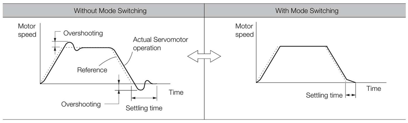
◆ Related Parameters
Select the switching condition for mode switching with Pn10B = n.▯▯▯X.
|
Parameter |
Mode Switching Selection |
Parameter That Sets the Level |
When Enabled |
Classification |
||
|
Rotary Servomotor |
Linear Servomotor |
|||||
|
Pn10B |
n.▯▯▯0 |
Use the internal torque |
Pn10C |
Immediately |
Setup |
|
|
n.▯▯▯1 |
Use the speed reference as the condition. |
Pn10D |
Pn181 |
|||
|
n.▯▯▯2 |
Use the acceleration |
Pn10E |
Pn182 |
|||
|
n.▯▯▯3 |
Use the position deviation as the condition. |
Pn10F |
||||
|
n.▯▯▯4 |
Do not use mode switching. |
− |
||||
|
■ |
Parameters That Set the Switching Levels |
• Rotary Servomotors
|
Pn10C |
Mode Switching Level for Torque Reference |
Speed |
Position |
|||||
|
Setting Range |
Setting Unit |
Default Setting |
When Enabled |
Classification |
||||
|
0 ~ 800 |
1% |
200 |
Immediately |
Tuning |
||||
|
Pn10D |
Mode Switching Level for Speed Reference |
Speed |
Position |
|||||
|
Setting Range |
Setting Unit |
Default Setting |
When Enabled |
Classification |
||||
|
0 ~ 10000 |
1min-1 |
0 |
Immediately |
Tuning |
||||
|
Pn10E |
Mode Switching Level for Acceleration |
Speed |
Position |
|||||
|
Setting Range |
Setting Unit |
Default Setting |
When Enabled |
Classification |
||||
|
0 ~ 30000 |
1min-1/ s |
0 |
Immediately |
Tuning |
||||
|
Pn10F |
Mode Switching Level for Position Deviation |
Position |
||||||
|
Setting Range |
Setting Unit |
Default Setting |
When Enabled |
Classification |
||||
|
0 ~ 10000 |
1 reference unit |
0 |
Immediately |
Tuning |
||||
|
■ |
Using the Internal Torque Reference as the Mode Switching Condition (Default Setting) |
When the Internal torque reference equals or exceeds the torque set for the mode switching level for
torque reference (Pn10C), the speed loop is changed to P control. The default setting for the torque
reference level is 200%.
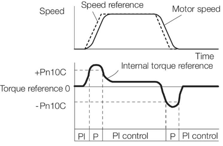
■ Using the Speed Reference as the Mode Switching Condition
• Rotary Servomotors
When the speed reference equals or exceeds the speed set for the mode switching level for a speed reference (Pn10D), the speed loop is changed to P control.
■ Using the Acceleration as the Mode Switching Condition
• Rotary Servomotors
When the speed reference equals or exceeds the acceleration rate set for the mode switching level for acceleration (Pn10E), the speed loop is changed to P control.
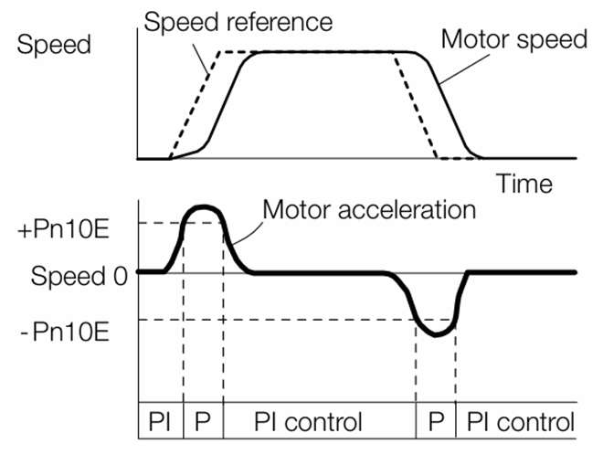
◆ Using the Position Deviation as the Mode Switching Condition
When the position deviation equals or exceeds the value set for the mode switching level for position
deviation (Pn10F), the speed loop is changed to P control. This setting is enabled only for position control.
Position Integral
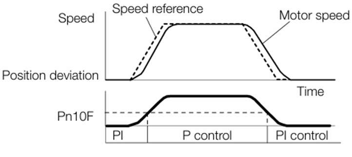
The position integral is the integral function of the position loop. It is used for the electronic cams and electronic shafts when using the servo driver with a Yaskawa MP3000-Series Machine Controller.
|
Pn11F |
Position Integral Time Constant |
Position |
|||||
|
Setting Range |
Setting Unit Position |
Default Setting |
When Enabled |
Classification |
|||
|
0 ~ 50000 |
0.1ms |
0 |
Immediately |
Tuning |
|||





|
12.13 Diagnostic Tools |
12.13.1 Easy FFT
The machine is made to vibrate and a resonance frequency is detected from the generated vibration to set notch filters according to the detected resonance frequencies. This is used to eliminate high-frequency vibration and noise.
During execution of Easy FFT, a frequency waveform reference is sent from the servo driver to the Servomotor to automatically cause the shaft to rotate multiple times within 1/4th of a rotation, thus causing the machine to vibrate. Execute Easy FFT after the servo is turned OFF if operation of the servo driver results in highfrequency noise and vibration
WARNING
Never touch the Servomotor or machine during execution of Easy FFT. Doing so may result in injury.
CAUTION
Use Easy FFT when the servo gain is low, such as in the initial stage of servo tuning. If you execute Easy FFT
after you increase the gain, the machine may vibrate depending on the machine characteristics or gain balance.
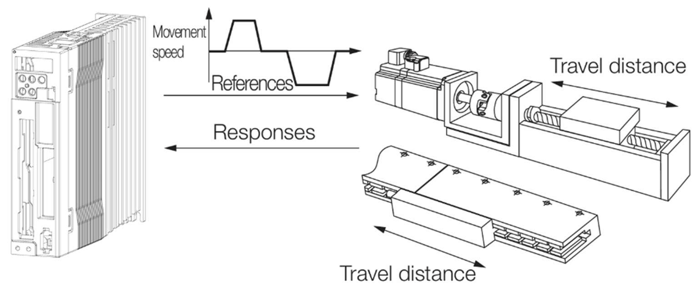
Easy FFT is built into the servo driver for compatibility with previous products. Normally use autotuning
without a host reference for tuning.
Preparations
Always check the following before you execute Easy FFT.
• The parameters must not be write prohibited.
• The main circuit power supply must be ON.
• There must be no alarms.
• The servo must be OFF.
• There must be no overtravel.
• An external reference must not be input.
Operating Procedure
Use the following procedure
1. Click the ServoDrive Button in the workspace of the Main Window of the Protuner.
Select Easy FFT in the Menu Dialog Box.
The Easy FFT Dialog Box will be displayed.
Click the Cancel Button to cancel Easy FFT. You will return to the main window
2. Click the Servo ON Button.
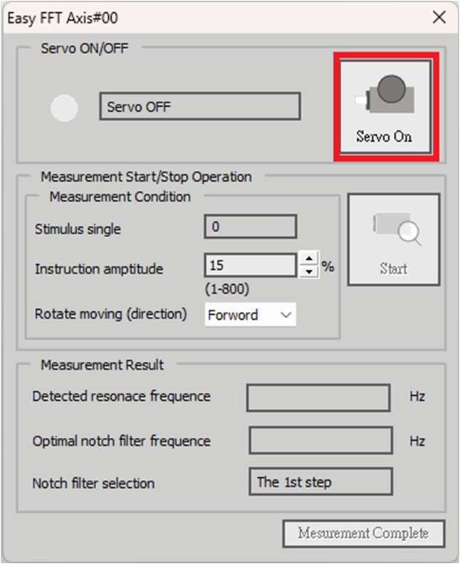
3. Select the instruction (reference) amplitude and the rotation direction in the Measurement condition Area,
and then click the Start Button.
The Servomotor shaft will rotate and measurements will start.
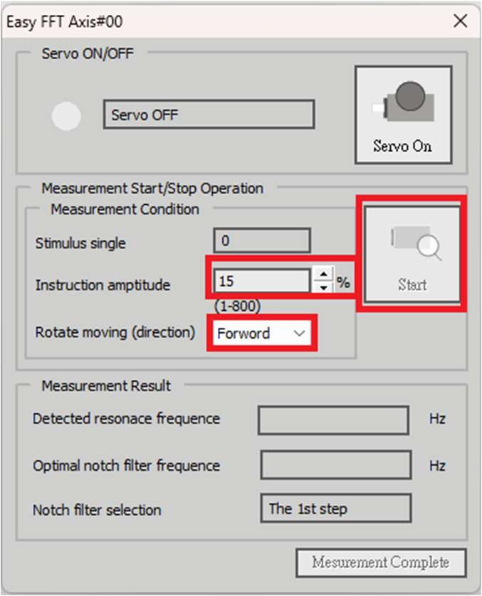
When measurements have been completed, the measurement results will be displayed.
4. Check the results in the Measurement result Area and then click the Measurement complete Button.
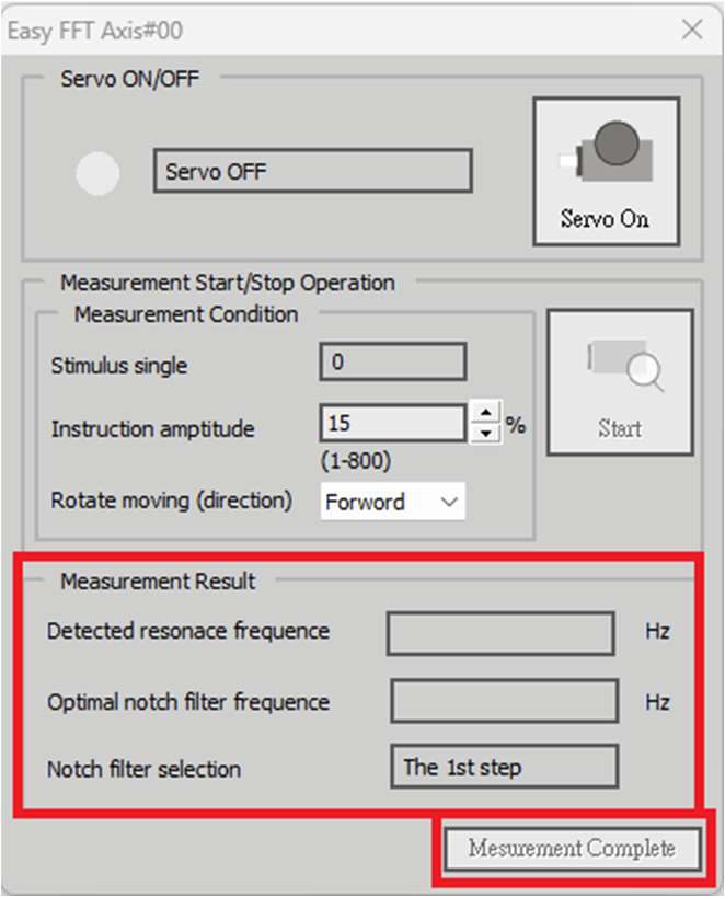
5. Click the Result Writing Button if you want to set the measurement results in the parameters.
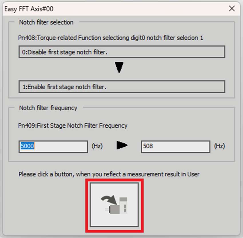
This concludes the procedure to set up
Related Parameters
The following parameters are automatically adjusted or used as reference when you execute Easy FFT. Do not change the settings of these parameters during execution of Easy FFT.
|
Parameter Pn408 |
Name |
Automatic Changes |
|
Torque-Related Function Selections |
Yes |
|
|
Pn409 Pn40A |
First Stage Notch Filter Frequency |
Yes |
|
First Stage Notch Filter Q Value |
No |
|
|
Second Stage Notch Filter Frequency |
Yes |
|
|
Second Stage Notch Filter Q Value |
No |
|
|
Pn456 |
Sweep Torque Reference Amplitude |
No |
Yes: The parameter is automatically set.
No: The parameter is not automatically set, but the setting is read during execution.
|
12.14 Modbus |
Read/W |
Length |
|||
|
Unit |
Comment |
||||
|
Address |
Name |
||||
|
rite |
|||||
|
0x0000-0x07FF |
Paramaters |
— |
RW |
Reference |
Auto back up to ERROM and saved |
|
Manual |
when power off |
||||
|
0x1000-0x17FF |
Paramaters |
— |
RW |
Reference |
Not back up to ERROM and not saved |
|
Manual |
when power off |
||||
|
0xC060 |
Motor SN |
RO |
16 |
||
|
0xE000 |
Motor Speed |
rpm |
RO |
16 |
Un000 |
|
0xE001 |
Speed Reference |
rpm |
RO |
16 |
Un001 |
|
0xE002 |
Torque Reference |
1% |
RO |
16 |
Un002 |
|
0xE005 |
Rotational Angle 2 |
deg |
RO |
16 |
Un004 |
|
0xE006 |
Input Signal Monitor |
— |
RO |
16 |
Un005 |
|
0xE007 |
Output Signal Monitor |
— |
RO |
16 |
Un006 |
|
0xE008 |
Input Reference Pulse Speed |
rpm |
RO |
16 |
Un007 |
|
0xE009 |
Position Deviation |
Reference |
RO |
32 |
Un008 |
|
Units |
|||||
|
0xE00B |
Accumulated Load Ratio |
1% |
RO |
16 |
Un009 |
|
0xE00C |
Regenerative Load Ratio |
1% |
RO |
16 |
Un00A |
|
0xE00D |
Dynamic Brake Resistor Power Consumption |
RO |
16 |
Un00B |
|
|
1% |
|||||
|
Reference |
|||||
|
0xE00E |
Input Reference Pulse Counter |
RO |
32 |
Un00C |
|
|
Units |
|||||
|
0xE010 |
Feedback Pulse Counter |
Pulse |
RO |
32 |
Un00D |
|
0xE012 |
Fully-closed Loop Feedback Pulse Counter |
RO |
32 |
Un00E |
|
|
Pulse |
|||||
|
Reference |
|||||
|
0xE01B |
Feedback Pulse Counter |
RO |
32 |
Un013 |
|
|
Units |
|||||
|
0xE040 |
Absolute Encoder Multiturn Data |
Turn |
RO |
16 |
Un040 |
|
0xE041 |
Position within One Rotation of Absolute Encoder |
RO |
32 |
Un041 |
|
|
Pulse |
|||||
|
Reference |
|||||
|
0xEC00 |
Absolute Position |
RO |
32 |
Un070 |
|
|
Units |
|||||
|
0xE110 |
Servo Inteneral Status |
— |
RO |
32 |
|
|
bit0 Main Circuit |
bit16 Motor Power Status |
||||
|
bit1 Encoder (PGRDY) |
bit17 Reserve |
||||
|
bit2 Motor Power (Request) |
bit18 Overcurrent |
||||
|
bit3 Dynamic Brake (DB) |
bit19 Origin Not Passed |
||||
|
bit4 Rotation (Movement) Direction |
bit21 Polarity Detection |
||||
|
bit5 Mode Switch |
bit22 Polarity Detection Completed |
||||
|
bit6 Speed Reference |
bit23 Reserve |
||||
|
bit7 Torque Reference |
bit26 Clear Signal (CLR) |
||||
bit8 Position Reference
bit9 Position Reference Direction
bit10 Reserve
|
bit11 Return To The Zero Position Completed |
|
bit12 AC Power ON |
bit13 CHARGE OK
|
Bit6 NCL Bit3 TGON Bit4 S-RDY 1:Alarm 3:POT NOT 4:POT 5:NOT 6:bb 7:run 8:RUN Polarity Detection A:Fstp |
||||
|
0xE51C |
||||
|
Servo Control Mode |
— |
RO |
16 |
|
|
|
0xE130 |
Bit15 Gain Selection 2 |
— |
RO |
32 |
|
Servo Inteneral Output Status |
Bit0 ALARM
Bit1 COIN
Bit2 V-CMP
|
Bit9 NEAR |
|||||
|
0xE140 |
DC-Link Voltage |
1V |
RO |
16 |
Un140 |
|
0xE50A |
Current Alarm State |
— |
RO |
16 |
|
0xE517 |
Servo Software Version |
— |
RO |
32 |
|
0xE51B |
Servo Status |
— |
RO |
16 |
bit14 Regenerative Transistor
|
0xE120 |
bit15 Regenerative Error Detection |
— |
RO |
32 |
|
Servo Inteneral Inputs Status |
||||
|
Bit0 S-ON |
Bit16 PDET |
|||
|
Bit1 P/PI Switch |
Bit17 FSTP |
|||
|
Bit2 P-OT |
Bit18-Dec |
|||
|
Bit3 N-OT |
Bit19 EXT0 |
|||
|
Bit4 ALM_RESET |
Bit20 EXT1 |
|||
|
Bit5 PCL |
Bit21 EXT2 |
|
||||||
|
bit0 PGM-START bit1 HOME-START bit2 PGM-STEP bit3 PGM-SEL0 |
bit4 PGM-SEL1 bit5 PGM-SEL2 bit6 PGM-SEL3 bit7 Reserve
bit8 Reserve bit9 Reserve bit10 Reserve bit11 PDET
bit12 SON bit13 ALM_RESET bit14 Dec bit15 Reserve
bit16 P-OTReserve bit17 N-OTReserve bit18 PCL bit19 NCL
bit20 CLR bit21 PCON bit22 ZCLAMP bit23 INHIBIT
bit24 PSEL bit25 SPD bit26 SPA bit27 SPB
|
bit28 CSEL bit29 GSEL bit30 SEN bit31 FstpReserve |
||
|
|
When using Modbud RTU to control the servo (in internal program table position control mode), Pn000 needs to be set to 00C0 (control mode setting C is position control running with internal program).
Internal program operation related parameters:
Pn640:
Hex0 (PGM-START): 0~7 are controlled by CN1 IO input, 8 is fixed as invalid, can be controlled by external communication, 9 is fixed as valid, ignore external communication and CN1 IO control
Hex1 (PGM-STEP): 0~7 are controlled by CN1 IO input, 8 is fixed as invalid, can be controlled by external communication, 9 is fixed as valid, ignore external communication and CN1 IO control
Pn641:
Hex0 (Program step 0 / SEL0 signal): 0~7 are controlled by CN1 IO input, 8 is fixed as invalid, can be controlled by external communication, 9 is fixed as valid, ignore external communication and CN1 IO control
Hex1 (Program step 1 / SEL1 signal): 0~7 are controlled by CN1 IO input, 8 is fixed as invalid, can be controlled by external communication, 9 is fixed as valid, ignore external communication and CN1 IO
Hex2 (Program step 2 / SEL2 signal): 0~7 are controlled by CN1 IO input control, 8 is fixed as invalid, can be controlled by external communication, 9 is fixed as valid, ignore external communication and CN1 IO
Hex3 (Program step 2 / SEL3 signal): 0~7 are controlled by CN1 IO input, 8 is fixed as invalid, can be controlled by external communication, 9 is fixed as valid, ignore external communication and CN1 IO
Control bit 0x2700 Communication input description:
1. The entire register must be written once with a single 32-bit integer.
2. Please fill in 0 for unused or reserved bits.
Example:
Communication control servo SON sets Bit 12 to 1 (0=Servo off 1= Servo on) 0x2700=0000 0000 0000 0000 0000 0001 0000 0000 0000(0x1000)
Communication command
01 10 27 00 00 02 04 00 00 10 00 41 9E
Set the position and speed of program step 0
0x0800=1 (=0 absolute position =1 relative position) 0x0801-0x0802 Target position (command unit) 0x0801=C350 Set the target position low bit to 50000 pulses
0x0802=0000 Set the target position high bit to 0
0x0803=01F4 Set the running speed to 300 rpm (speed unit 100 pulses/s, 500*100*60/10000=300 rpm) Communication command
01 10 08 00 00 04 08 00 01 C3 50 00 00 01 F4 68 DA
Communication selection execution program step 0
Servo SON must be issued first
0x2700=0000 0000 0000 0000 0000 0001 0000 0000 0000(0x1000)
Communication command
01 10 27 00 00 02 04 00 00 10 00 41 9E
Select execution of program step 0 bit0=1 bit2=1 bit3=1
0x2700=0000 0000 0000 0000 0001 0000 0000 1101(0x0001000D)
Communication command
01 10 27 00 00 02 04 00 00 00 0D 8D 9B
After the program step is completed, if you need to execute other program steps or repeat the execution, you must set bit2=0 and only keep the SON state
0x2700=0x 0000 0000 0000 0000 0000 0001 0000 0000 0000(0x1000)
Communication command
01 10 27 00 00 02 04 00 00 10 00 41 9E
Repeat execution and issue again
Select execution program step 0 bit0=1 bit2=1 bit3=1
0x2700=0000 0000 0000 0000 0001 0000 0000 1101(0x0001000D)
Communication command
01 10 27 00 00 02 04 00 00 00 0D 8D 9B
Select other steps, such as step 3
bit0=1 bit2=1 bit3=1 bit4=1(bit3~ bit6 are combined into 1 word to indicate the step number)
0x2700=0000 0000 0000 0000 0001 0000 0001 1101(0x0001011D)
Communication command
01 10 27 00 00 02 04 00 00 00 1D 8C 57
(Note) The action mode of PGM-START(bit0) is that when the signal is written to 0, it will stop immediately. If it is written to 1 again, PGM-STEP(bit2) needs to be re-triggered (the writing action is from 0->1)
Internally set speed switching input (SPD, SPA, SPB) signal operation related parameters:
Pn000: 3
Pn301~Pn303: Set the operation speed
After the setting is completed, the communication can be written to bit25 (SPD), bit26 (SPA), bit27 (SPB)
Tip: press ← → to switch chapters, Ctrl+K to search