Objects such as【Lamp】or【Numeric Input/Display】can be used to read the real-time changes of certain register values when the HMI is operating. However, in order to track changes of the value over time, the【Data Log】function must be used. The【Data Log】 function is used to log the values of an address according to a set interval or when certain conditions are met to provide users with the long-term trends of values in addresses.
This chapter will explain Data Log functions, the settings, and how to export the data for the user to view and analyze.
7.1 Data Log List
Click on【Data Log】in the【Project Explorer】of FvDesigner, and the【Data Log List】 will pop up; the current【Data Log Groups】that were already set will be displayed on the list according to the order of the【Group ID】.

Figure 122【Data Log List】Screen
To add a new Data Log Group, click on the【Add】button to the right and the【Data Log Group】setting dialog will appear for the user to operate.
To edit an existing 【Data Log Group】, double-click on the【Data Log Group】entry or first select the【Data Log Group】entry and then click on the【Edit】button to the right. The properties setting dialog of the【Data Log Group】entry will appear for the user to modify.
To delete an existing 【Data Log Group】, select the【Data Log Group】entry and then click on the【Delete】button to the right to delete this【Data Log Group】entry.
7.2 Data Log Group Settings
Settings for the【Data Log Group】are divided into four parts:【Setting】,【Logging Address List】,【Export Data】and【Print Data】.【Setting】is used to set the behavior for the【Data Log Group】to log the data, the【Data Address List】is used to edit the address list logged by the【Data Log Group】, and the【Export Data】is used to set the export behavior of the logged data,【Print Data】is used to set the format to print out the data log.
7.2.1 【Setting】
The【Setting】screen is as shown in the figure below. The meaning of each setting are also listed below:
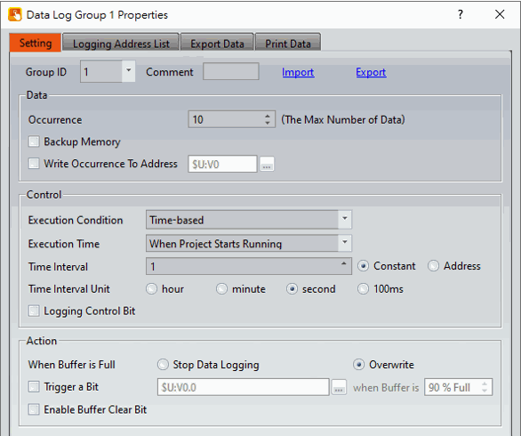
Figure 123【Setting】of【Data Log Group】
Table 51【Setting】Properties of【Data Log Group】
|
Property |
Description |
||||
|
【Group ID】 |
Set the Group ID of the【Data Log Group】. |
||||
|
【Comment】 |
Set a comment for the【Data Log Group】. |
||||
|
【Import】 |
A CSV , xlsx or xls file can be selected after clicking on this button. All the logged addresses included in the file will be applied to the【Data Log Group】settings. |
||||
|
【Export】 |
The settings of the current【Data Log Group】can be saved into a CSV , xlsx or xls file after clicking on this button. |
||||
|
【Data】 |
Set the data content logged by the【Data Log Group】. 【Occurrence】 Set the number of times to collect data 【Backup Memory】 Set to enable Backup Memory. Select to save the Data Log of the HMI into the backup memory of the HMI when the power of the HMI is interrupted in order to avoid loss of data. 【Occurrence】 Set the number of times【Data Log Group】 logs data. |
||||
|
【Control】 |
Set the conditions for the【Data Log Group】to log data. 【Execution Condition】 Sets the condition to execute data logging. 【Time-based】 The【Data Log Group】will log data according to a set interval. 【Triggered by Bit】 The address logging will be executed when the status changes of the 【Logging Control Bit】satisfy the conditions set in【Trigger Condition】.
|
||||
|
【Action】 |
【When Buffer is Full】 Set the action to take when the【Data Log Group】has completed the number of data loggings set in【Occurrence】. If【Stop Data Logging】is selected, data logging will be stopped; if【Overwrite】is selected, then the【Data Log Group】will continue to log data and the data previously saved will be overwritten as new data is logged. 【Trigger a Bit】 Set to trigger a specific bit when the data is full; the triggering address and the time to trigger the address can be set on the right if this is enabled. 【Enable Buffer Clear Bit】 Set to enable a buffer clear bit; the【Buffer Clear Bit】can be set at the right if this is enabled. When the status of this address is 1, the data saved in the buffer will be cleared. |
7.2.2 【Logging Address List】
The【Logging Address List】screen is as shown in the figure below, the meaning of each setting are listed below:
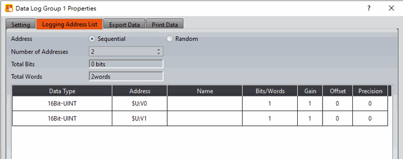
Figure 124【Logging Address List】Setting Screen of【Data Log Group】
Table 52【Logging Address List】Setting Properties of【Data Log Group】
|
Property |
Description |
|
【Address】 |
You can choose whether to automatically【continuous】address when creating the address, or【random】to be filled in by the user. |
|
【Number of Addresses】 |
Set how many addresses to collect. |
|
【Total Bits】 |
Display the total bits of the data logged. |
|
【Total Words】 |
Display the total words of the data logged. |
|
【Logging Address List】 |
【Data Type】 Set the data type of the data logged. Only the first row can be modified if the logged address type is set as【Sequential】. 【Address】 Set the address of the data logged. Only the first row can be modified if the logged address type is set as【Sequential】. 【Name】 Set the address name of the data logged; the default name is the address is itself if no name is entered. 【Bits/Words】 Display the length of the data logged by【Data Type】.【Words】can be modified if【Data Type】is set as【Ascii String】. 【Gain】 The amount of【Gain】can be set. Formula is as follows: y=Ax+B, gain is A, offset for the B, y value is displayed for HMI, x is PLC value. 【Offset】 Set the【Offset】value. See【Gain】for more details. 【Precision】 Set the amount of decimal places shown. |
7.2.3 【Export Data】
The【Export Data】screen is as shown in the figure below, the meaning of each setting are listed below:
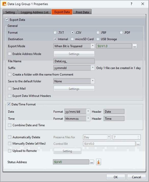
Figure 125【Export Data】Setting Screen of【Data Log Group】
Table 53【Export Data】Setting Properties of【Data Log Group】
|
Property |
Description |
||||||||||||||||||||||||||||||||||||||||||||
|
【Export Data】 |
Set to enable to export data function; export settings will appear below if this function is enabled. |
||||||||||||||||||||||||||||||||||||||||||||
|
【Format】 |
Set the format of the output file; TXT, CSV, FBF, and PDF can be selected, FBF file is FATEK’s proprietary format, which requires the format of reading or converting files using【FBF Reader】in FvDesigner【Tools】. |
||||||||||||||||||||||||||||||||||||||||||||
|
【Destination】 |
Set the destination of the output file; available selections include internal, microSD card or USB storage device. If the output destination is internal storage, you can use FTP to connect to the HMI to read the stored file. |
||||||||||||||||||||||||||||||||||||||||||||
|
【Export Mode】 |
Set the timing of exporting files. There are four operation modes when the drop-down menu is clicked.
|
||||||||||||||||||||||||||||||||||||||||||||
|
【Enable Continue File Mode】 |
Support for PC model with FBF export data format, Historic Trend and Historic Data Table will load the old files automatically if this option is checked. But at the same time, 【Enable Address Mode】and the Sub switch save in the 【Historic Data Table】will be disabled to avoid time repeat. |
||||||||||||||||||||||||||||||||||||||||||||
|
【Enable Address Mode】 |
After enabling, the exported file name, destination, suffix, export mode, data mode, date and time filtering, etc., will be controlled by the specific address. To be allowed to enable this mode, you need to first enable【Export Mode】and【When Bit is Triggered】. When【Export Mode】is【When Buffer is Full】, the export method cannot be set. 【Setting】
【File Name】 Use a defined address to set the name of the exported file. 5 characters is the default setting, maximum setting is 100 characters. 【Destination】 Use a defined address to set the destination of the output file. The destination values are shown in the following table,
【Suffix】 Use a defined address to set the name of the exported file and the date/time format. The suffix values are shown in the following table,
【Export Mode】 Use a defined address to set the export mode. The export mode values are shown in the following table,
【Data Mode】 Use a defined address to set the data mode of the exported data. The data mode values are shown in the following table,
【Data/Time Filter】 【Start Date (Year/Month/Day)】 Use a defined address to set the date at which filtering starts. 【Start Time (Hour/Minute/Second)】 Use a defined address to set the time to start filtering. 【End Date (Year/Month/Day)】 Use a defined address to set the date at which filtering ends. 【End Time (Hour/Minute/Second)】 Use a defined address to set the time at which filtering ends. |
||||||||||||||||||||||||||||||||||||||||||||
|
【File Name】 |
Set the name of the exported file; the file name of the exported file includes the save date and time (such as: DataLog_140519_151735.txt). |
||||||||||||||||||||||||||||||||||||||||||||
|
【Suffix】 |
Set the name of the exported file, such as yymmdd_hh, the name of exported file only has a date and hours (Example: DataLog_140519_17.txt) This setting also provides regular export archive mode, If the suffix selected is "yymm", it would produce one file per month, If the suffix selected is "yymmdd", it would produce one file per day, If the suffix select "yymmdd_hh", it would produce one file per hour, If the suffix selected is " yymmdd_hhmm", it would produce one file per minute, If the suffix selected is " yymmdd_hhmmss", it would produce one file per second, If the suffix to select "no", one file includes all data. |
||||||||||||||||||||||||||||||||||||||||||||
|
【Create a folder with the name from comment】 |
If this option is checked, the name of the folder will be name from【Setting】【Comment】, for example, comment temperature, the original Group_1 folder will be changed to the temperature folder, which is originally datalog \ Group_1 will become datalog \ temperature. |
||||||||||||||||||||||||||||||||||||||||||||
|
【Save to the default folder】 |
There is None, Folder created monthly and Folder created daily 3 opitons. If choose none then will not create another folder,for example, datalog\Group_1\DataLog_170403. csv. If choose folder created monthly then will create another monthly folder each month, for example, datalog\Group_1\201704\DataLog_170403.csv. |
||||||||||||||||||||||||||||||||||||||||||||
|
【Send Mail】 |
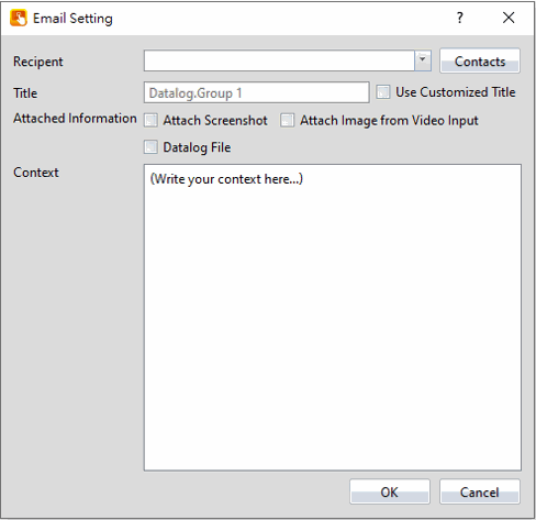
It can be seen after【SMTP】is enabled. The purpose of this function is to send emails when exporting. The details are as follows: When this group has exported data, an email will be sent to the set group according to the settings here. At the same time, you can check to include "Datalog File (the file exported this time)" and send it together.
|
||||||||||||||||||||||||||||||||||||||||||||
|
【Export Data Without Headers】 |
After checking, the title will not be exported when exporting data. (*Note: If you want to write a file with an existing title, the title of the file will still exist, please delete the old file before using this function)
|
||||||||||||||||||||||||||||||||||||||||||||
|
【PDF Setting】 |
When the export format is set to PDF, clicking settings allows you to adjust the PDF document style. |
||||||||||||||||||||||||||||||||||||||||||||
|
【Date/Time Format】 |
【Date】 Set the display format of the date when exporting files. 【Time】 Set the display format of the time when exporting files. 【Combine Date and Time】 If set, the date and time columns will be combined into a single column. |
||||||||||||||||||||||||||||||||||||||||||||
|
【Automatically Delete】 |
Check to set the number of days the exported file should be retained in memory. For example, if set to seven days, the HMI will use its internal calendar and files greater than seven days will be removed. |
||||||||||||||||||||||||||||||||||||||||||||
|
【Manually Delete (all files)】 |
It will delete all files when the bit turns to ON. |
||||||||||||||||||||||||||||||||||||||||||||
|
【Upload to Remote】 |
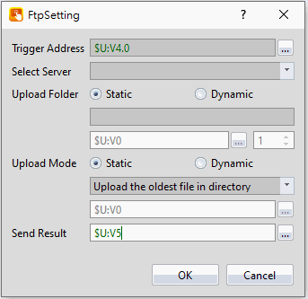
Enable ch4.5-【FTP Client】function then this option can be seen.
【Trigger Address】 Set a bit to trigger uploading. 【Select Server】 Click the drop-down menu to select the server to upload 【Upload Folder】 Fill in the path where the remote server is stored, if not filled in, it will be stored in the root directory of the server 【Upload mode】 There are 7 upload modes for【Static】, which will be described together with【Dynamic】below
【Send Result】 Set the address of the execution result display, the data type is【INT】, Success: 1 / Failure: -1 |
||||||||||||||||||||||||||||||||||||||||||||
|
【Status Address】 |
Set the saving address of the error code.
|
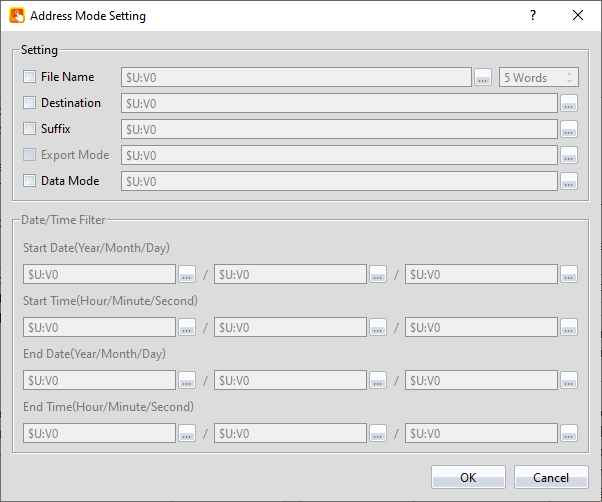

The following example exports specified time data:
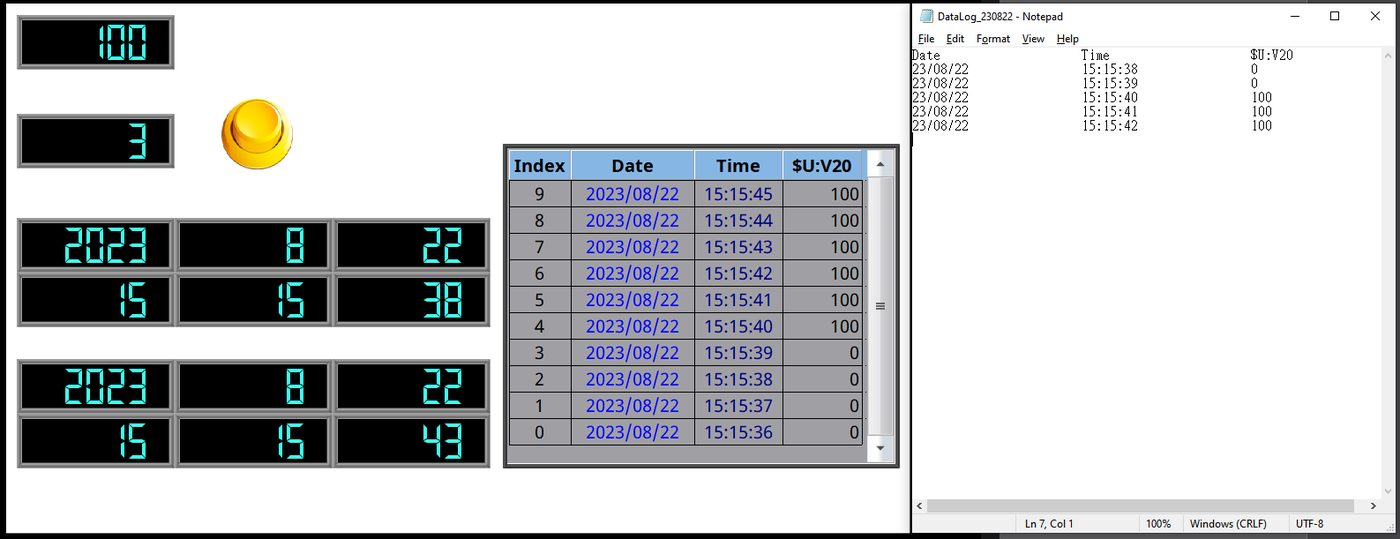
Figure 126 export specified time data example
Base on checking【Enable Address Mode】and【Data Mode】, set data 3 to【Data Mode】. Fill in fill in the required time range into the register that set in【Date/Time Filter】, datas between the range can be obtained.
7.2.4 【Print Data】
【Print Data】page as shown below, the meaning of each setting is as follows :
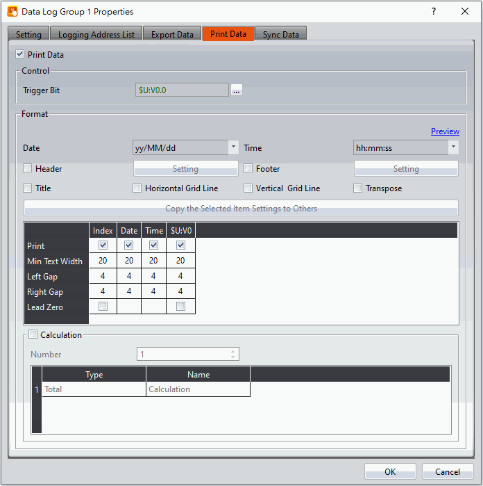
Figure 127【Print Data】Setting Screen of【Data Log Group】
Table 54【Print Data】Setting Properties of【Data Log Group】
|
Properties |
Description |
|
【Print Data】 |
Set whether to enable Print Data function, enable the function do the following settings. |
|
【Control】 |
【Trigger Bit】 Set the trigger bit of print control. |
|
【Format】 |
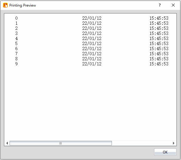
【Date】 Set the date print format. 【Time】 Set time print format. 【Header】 If checked, according to the setting, it will print header first then print the data log content. Press ‘’setting’’ button to set the header. 【Setting (Header)】 Header setting, please refer to 7.2.4.1-【Print Data】Header and Footer【Setting】for more details. 【Footer】 If checked, according to the setting, it will print data log content first then print the footer. Press ‘’setting’’ button to set the footer. 【Setting (Footer)】 Footer setting, please refer to 7.2.4.1-【Print Data】Header and Footer【Setting】for more details.。 【Title】 Print the data log title. 【Horizontal Grid Line】 Print out with horizontal grid line. 【Vertical Grid Line】 Print out with vertical grid line. 【Transpose】 Data will be printed from left to right. 【Preview】 Press the preview to view the following table settings, whether it meets the printing requirements, press ‘’preview’’ following figure will appear
|
|
【Print Items】 |
Print items includes: Index, Date, Time and Data. 【Copy the Selected Item Settings to Others】 When a certain row is selected, this button will be enabled. The user can use this button to copy the setting value of the selected item to other items, which simplifies the user’s setting procedure and improves the set efficiency. 【Print】 If checked, the printed data will include this item. 【Min Text Width】 The minimum expected text width of the print items, when the text width of the content is smaller than the minimum word width, will be automatically filled with spaces to keep the minimum word width setting. The letter width of the letter or number is 1 and the Chinese is 2 . 【Left Gap】 Space on the left of the print item 【Right Gap】 Space on the right of the print item 【Lead Zero】 For Data Log’s items that are not ‘’text’’ type, when the width of the printed content is less than the minimum width, it will automatically filled with ‘’0’’. |
|
【Calculation】 |
After the actual data that collected, will calculate for data log items that are not "text" types, and the calculation results will be printed in sequence. 【Number】 Set the number of calculations. The following is the setting description of the calculation item: 【Type】 Set the type of calculation, includes Total, Average, Maximum and Minimum. 【Name】 Calculate the customized name of the project, which will be printed with the calculation results. |
7.2.4.1 【Print Data】Header and Footer【Setting】
For the header/footer, when click the【Setting】button, the following dialog box appears. There are two modes:【Static】and【Dynamic】.
【Static】
Users can edit any text content as static header/footer content.
【Dynamic】
The user sets the variables and edits the pattern, and matches the keyword "%[number]" (eg: %1, %2, %3, etc.) to achieve the dynamic header/footer requirements, where the keyword will be replaced by the actual content of the variable.
【Dtat Log】【Print Data】【Header/Footer】as shown in the figure below, the meaning of each setting option is as follows:
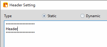
Figure 128【Print Data】【Header/Footer】Setting Screen of【Data Log Group】(Static mode)
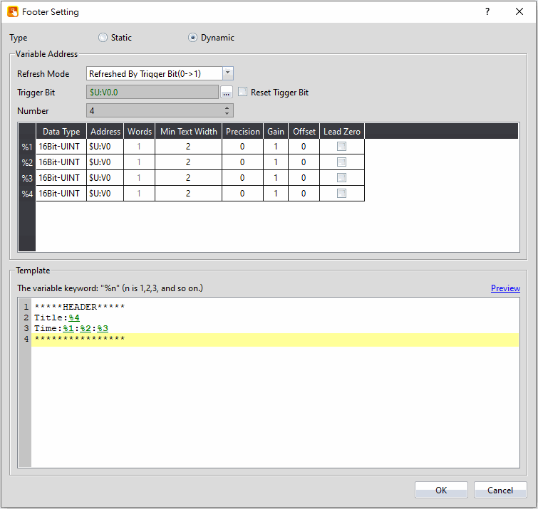
Figure 129【Print Data】【Header/Footer】Setting Screen of【Data Log Group】(Dynamic mode)
Table 55【Export Data】Setting Properties of【Data Log Group】
|
Options |
Description |
|
【Variable Address】 |
【Refresh Mode】 The refresh mode for setting variable content can be divided into:
【Trigger Bit】 Set the refresh variable content trigger address. This setting only needs to set when【Refresh Mode】 is【Refreshed By Trigger Bit(0->1)】、【Refreshed By Trigger Bit (1->0)】or【Refreshed By Trigger Bit Changed】. 【Reset Trigger Bit】 Whether to reset trigger bit after refreshing variables. This setting only needs to set when【Refresh Mode】 is【Refreshed By Trigger Bit(0->1)】or【Refreshed By Trigger Bit (1->0)】. 【Number】 Set the number of variables. |
|
【Variable】 |
【Data Type】 Set the data type of variable. 【Address】 Set the address of variable. 【Words】 The number of words required of data types to display variables. If【Data Type】is【Ascii String】, then can set the number of words to collect at the beginning of the address. 【Min Text Width】 Set the minimum text width of the variable content. When the word width of the content is smaller than the minimum word width, it will be automatically filled with spaces to keep the minimum word width setting. 【Precision】 Set the precision of the variable. 【Gain】 Set the gain of the variable. 【Offset】 Set the offset of the variable. 【Lead Zero】 For Data Log’s items that are not ‘’text’’ type, when the width of the printed content is less than the minimum width, it will automatically filled with ‘’0’’. |
|
【Template】 |
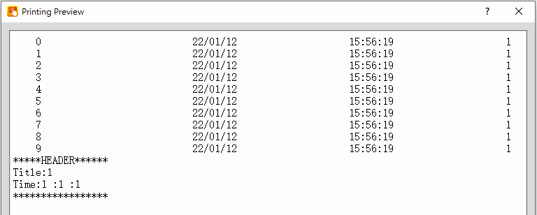
The user sets the variables and edits the pattern, and matches the keyword "%[number]" (eg: %1, %2, %3, etc.) to achieve the dynamic header/footer requirements, where the keyword will be replaced by the actual content of the variable. 【Preview】 For setting preview header/footer content, as shown below:
|
7.2.5 【Sync Data】
Synchronize the data from the database. When enabled, the data will be automatically read from the database when the connection is successful. If you want to view it in the【Historic Data Table】, select【Historic Data Table】in the【Source】of the【Historic Data Table】.
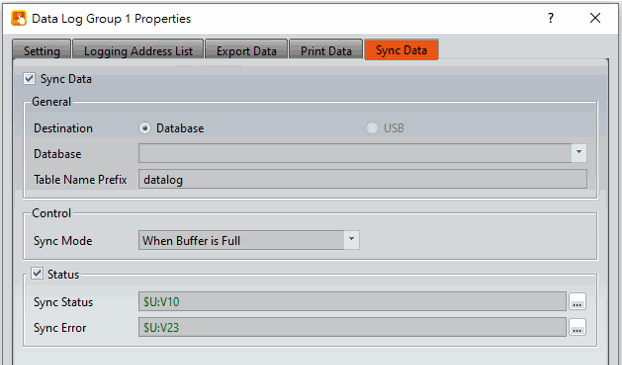
Figure 130【Data Log Group】【Sync Data】Setting Page
Table 56【Data Log Group】【Sync Data】Property Setting Page
|
Property |
Description |
||||||||||||||||||||||||||||||
|
【Sync Data】 |
Set whether to enable the data sync function. After enabling, the setting items will appear below. |
||||||||||||||||||||||||||||||
|
【General】 |
【Destination】 Set the synchronize destination 【Database】 Set the synchronize database 【Table Name Prefix】 Set the generated table name of the after synchronization. If FvDatalog is set in this field then will generate FvDatalog_data and FvDatalog_data_format 2 tables.
Note: When the Data Log setting has changed (but the table name is not changed), after downloading to the HMI, the synchronized data table in the database needs to be deleted first then the new Data Log will take effect. |
||||||||||||||||||||||||||||||
|
【Control】 |
【Sync Mode】 Set the timing of synchronizing data to the database, including When Buffer is Full, When Bit is Triggered, Daily Synchronization, and Sync Regularly. |
||||||||||||||||||||||||||||||
|
【Status】 |
【Sync Status】 Set the storage address of the status
【Sync Error】 Set error code storage address
|
Tip: press ← → to switch chapters, Ctrl+K to search