The alarm function is used to monitor value changes in specified registers. If the value exceeds the defined range, it will be recorded in the table. You can also configure it to issue an audible notification or send the report log via email through SMTP.
8.1 Alarm List
Click 【Alarm】in the function list on the left side of FvDesigner to open the settings page.
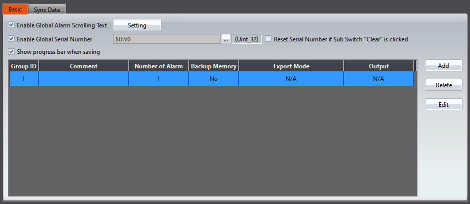
Figure 131【Alarm List】Screen
Table 57 【Alarm List】Property Setting Page
|
Property |
Description |
|
【Basic】 |
【Enable Global Alarm Scrolling Text】 【Enable Global Serial Number】 【Show progress bar when saving】 【Group】 |
|
【Sync Data】 |
This option is visible only when the project model is set to PC, and it is used to synchronize alarm data to a database. |
8.2 Alarm Setting
The properties of an【Alarm】is divided into【Setting】and【Export Data】, in which 【Setting】is used to set the behavior and occurrence conditions of the【Alarm】 and【Export Data】is used to set data export behaviors for alarms that already occurred.
8.2.1 【Setting】
The “Setting” screen is as shown in the figure below, the meanings of each setting are also listed below:
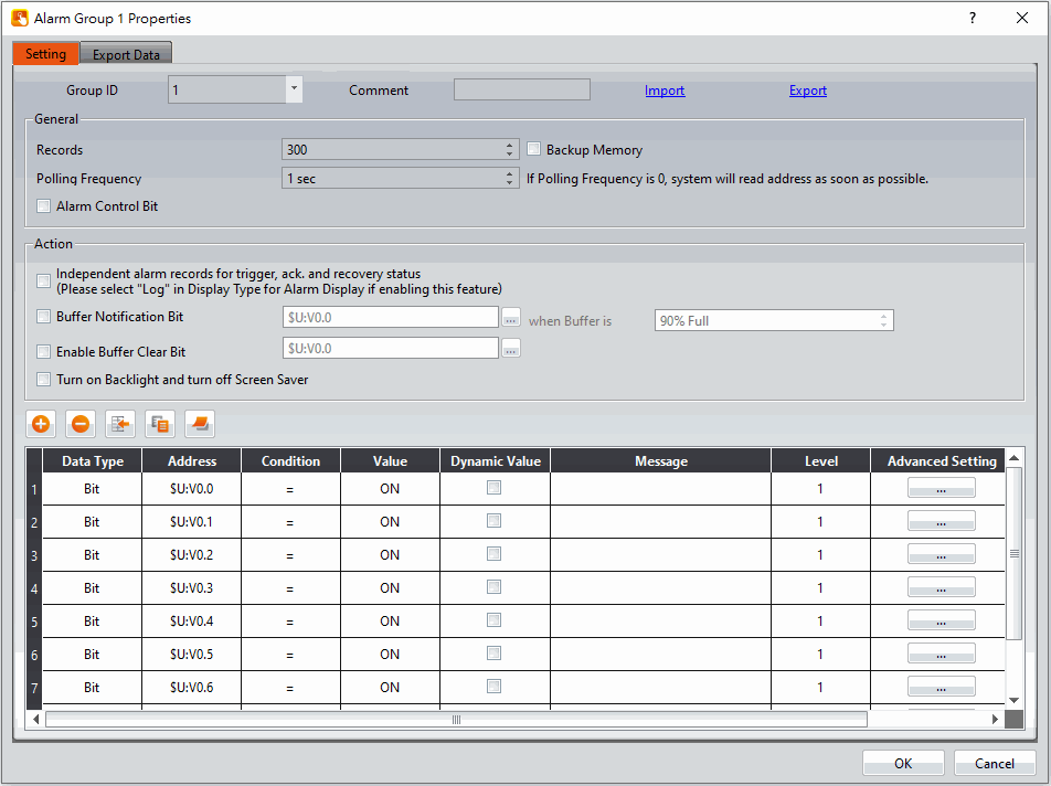
Figure 132【Setting】Screen of【Alarm】
Table 58【Setting】Properties of【Alarm】
|
Property |
Description |
||||||||||||||||||||
|
【Group ID】 |
Set the Group ID of the【Alarm】. |
||||||||||||||||||||
|
【Comment】 |
Set the comment of the【Alarm】. |
||||||||||||||||||||
|
【Import】 |
A CSV or Excel file file can be selected after clicking this option. All of the【Alarm】contents of the file will be applied to the current【Alarm】settings. |
||||||||||||||||||||
|
【Export】 |
The settings of the current【Alarm】can be saved into a CSV or Excel file after clicking this option. |
||||||||||||||||||||
|
【Group Setting】 |
【General】
【Action】
|
||||||||||||||||||||
|
【Add】 |
Adds an alarm entry to the bottom of the alarm table when this button is pressed. The alarm address will automatically increase. For example, if the bottommost entry in the alarm table has an address of M10, when the【Add】button is pressed, the new alarm entry will have an address of M11. When the【Data Type】is set to bit, the address will increase bitwise. |
||||||||||||||||||||
|
【Delete】 |
The alarm data selected in the alarm table below will be deleted when this button is pressed. |
||||||||||||||||||||
|
【Copy】 |
The alarm data selected in the alarm table below will be copied when this button is pressed. |
||||||||||||||||||||
|
【Paste】 |
A new alarm data entry will be added and the alarm settings copied will be filled into this new alarm entry when this button is pressed. |
||||||||||||||||||||
|
【Alarm Table】 |
Set the occurrence condition of the【Alarm】. 【Data Type】 Set the data type for the monitoring address of the【Alarm】. 【Address】 Set the monitoring address of the【Alarm】. 【Condition】 Set the condition to determine that an【Alarm】has occurred. 【Value】 Set a value to determine if an【Alarm】has occurred. 【Dynamic Value】 After checking,【Value】will become address mode for users to input. 【Message】 Set the message to display when an【Alarm】has occurred. 【Level】 Set the level (1~8) of this【Alarm】entry. This can be used to distinguish between different levels of alarm. 【Advanced Setting】 When the【Advanced Setting】button is pressed, a pop up dialog will appear for users to set the advanced settings for【Alarm】. |


8.2.2 【Advanced Setting】
The【Advanced Setting】properties setting dialog is as shown in the figure below, the meaning of each setting are listed below:
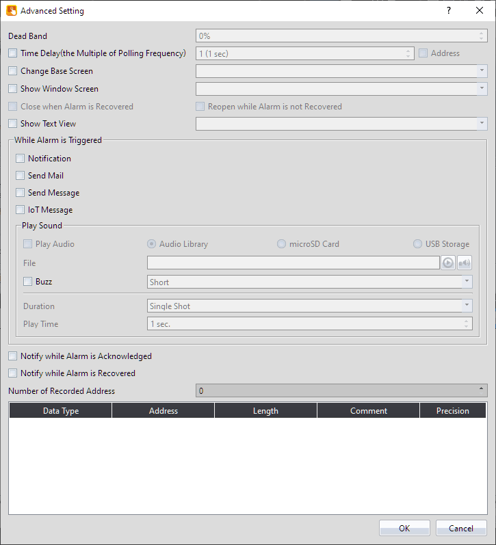
Figure 133【Advanced Setting】Property Setting Dialog of【Alarm】
Table 59【Advanced Setting】Properties of【Alarm】
|
Property |
Description |
|
【Dead Band】 |
Set the confirmed alarm recovery area after an【Alarm】occurred. For example, if the alarm occurrence condition is set as x>100, and【Dead Band】is set as 5%, then when x>100 the alarm occurs and when x<96 the alarm will recover. |
|
【Time Delay (the Multiple of Polling Frequency】 |
Set the delay time to do trigger delay. If the polling frequency set 1 second, time delay set 5, then the alarm will be triggered when all the conditions were met within 5 seconds. |
|
【Change Base Screen】 |
Set whether to enable the【Change Base Screen】function. If the function is enabled, you can select the【Base Screen】you want to change to when the alarm is triggered. |
|
【Show Window Screen】 |
Set to enable the【Show Window Screen】function. The corresponding【Window Screen】for this alarm entry can be selected on the right once this option is enabled. If this function is enabled when the alarm occurs, a window screen will display or a【Show Window】sub switch can be pressed on the【Alarm Display】object to display the【Window Screen】set for this alarm. 【Close when Alarm is Recovered】 When the alarm is restored, the corresponding window screen will automatically close. 【Reopen while Alarm is not Recovered】 The window screen for the alarm will constantly reopen unless the alarm recovers. |
|
【Show Text View】 |
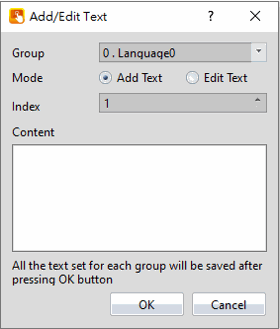
When an alarm occurs, you can click the alarm and call a text window through the【Sub Switch】. After clicking the drop-down menu, you can select the existing text in the【Text Library】to display, or add an index and content by yourself.
|
|
【While Alarm is Triggered】 |
Set to execute other behaviors when an alarm is triggered. 【Notification】 Set to notify specific addresses when an alarm is triggered. If this option is enabled, set the notification address and signal. Level: Set the bit as 0 or 1. Pulse: Set the bit to 1 and automatically restore to 0 after continuing the time set by【Width】. 【Send Email】 Checkable when 【SMTP】 is enabled. If enable, you can set the address of the person to be notified when the alarm occurs, as well as additional messages and files. For details, refer to ch8.2.3-【Send Email/Message Setting】 【Send Message】 Checkable when 【4G】 is enabled. If enable, you can set the address of the person to be notified when the alarm occurs, as well as additional messages and files. 【IoT Message】 When this option is enabled, messages will be sent to third-party software via the IoT cloud server when an alarm is triggered. 【Attached Image】When enabled, screenshots will be sent along with the message. However, please note that due to component update speeds, the image content may not correspond to the alarm content. 【Attached Information】Enabling this option allows the configuration information of 【Record Address】 in 【Setting】 to be sent together. 【Context】Enabling It is divided into 【Static】 and 【Dynamic】 and users can choose according to their needs. The receiving format can be previewed in 【Preview】.
(※*For inquiries on how to bind third-party software, please refer to Chapter 7 of the "FATEK IoT Cloud Service Manual" available for download at到hIttps://www.fatek.com/en/download.php?act=list&cid=16 ) 【Play Audio】 Set to play an audio file when an alarm is triggered. If this option is enabled, the audio set on the【Audio Selector】on the right which was selected from the【sound library】will be played when an alarm occurs. The【Duration】for the playback of the audio is controlled by the setting items below:【Single Shot】,【Time-based】,【Until Acknowledged or Recovered】and【Until Screen is Touched】are available for selection. When select enable and select the audio file is from microSD or USB storage, you can set the file name of the microSD or USB storage audio file, when alarm happens, will play the set of the audio, file name need to contain filename extention. If select【Address】, then the file name can be controlled by the set of the address. Build a audio file in the microSD or USB storage, and put the audio file in the audio folder, the audio file can be read by HMI when the alarm ring. 【Buzzer】 Sets whether or not to play the buzzer when the alarm is triggered. The buzzer sounds there are short, long, short-short, and long-short 4 ways. You can choose the buzz type, and adjust the【Duration】where you can choose【Single Shot】,【Time-Based】,【Until Acknowledged or Recovered】or【Until Screen is Touched】. 【Play Time】 When the【Time-based】option is selected, an option will appear and the play duration can be set. |
|
【Notify while Alarm is Acknowledged】 |
Set to notify specific addresses when an alarm is acknowledged. If this option is enabled, the notification address set on the right will be set or reset when an alarm is acknowledged. Level: Set the bit as 0 or 1. Pulse: Set the bit to 1 and automatically restore to 0 after continuing the time set by【Width】. |
|
【Notify while Alarm is Recovered】 |
Set to notify specific addresses when an alarm is recovered. If this option is enabled, the notification address set on the right will be set or reset when an alarm recovers. Level: Set the bit as 0 or 1. Pulse: Set the bit to 1 and automatically restore to 0 after continuing the time set by【Width】. |
|
【Number of Recorded Address】 |
Set the number of address to read when an alarm is triggered; it can be set between 1~8. When the number set is changed, the number of rows in the address record table below will also change accordingly. 【Data Type】 Set the data type of the address to read when an alarm is triggered. 【Address】 Set the address to read when an alarm is triggered. 【Comment】 Set the comment of the address to read when an alarm is triggered. This comment can allow users to identify what the address represents. 【Precision】 Set the decimal point of the recorded value displayed in the【Alarm Display】. |
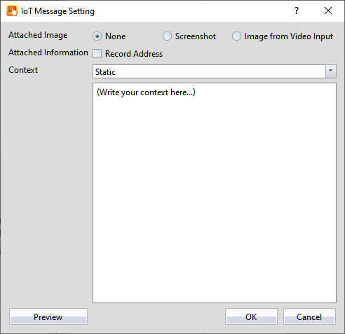
8.2.3 【Send Email/Message Setting】
The【Setting】dialog box for sending emails is shown in the figure below.
The meaning of each setting option is as follows:
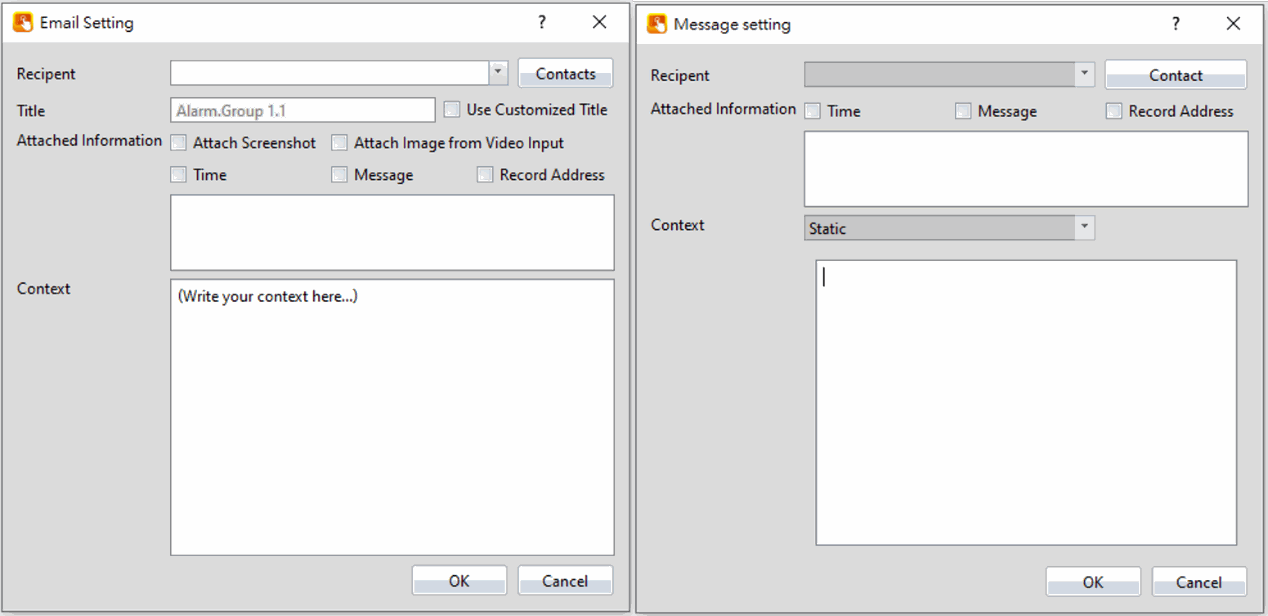
Figure 134【Advanced Setting】【Send Email/Message】Property Setting Dialog of【Alarm】
Table 60【Advanced Setting/Message】【Send Email】Properties of【Alarm】
|
Options |
Description |
|
【Recipent】 |
When the alarm occurs, the recipient of the email must first set the【Contacts】and【Groups】in the【Contact Lists】tab of the【SMTP】tab in【Severs】, or the【Contacts】button on the right set【Contacts】and【Groups】to be selected here. |
|
【Contacts】 |
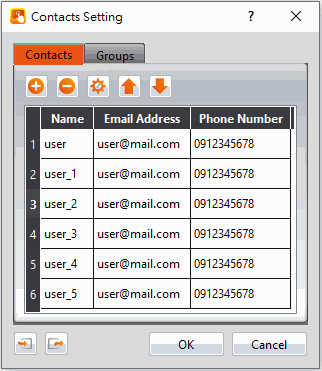
Provide the e-mail address of the person who receive the e-mail, and【Contacts】and【Groups】, etc. Press 【Contact Lists】, the following figure will appear, you can add, delete, edit, import, export, etc. For more details, refer to chapter4.3.1-【SMTP】setting.
|
|
【Title】 |
Title of email, the title will be group’s name if do not checked the【Use Customized Title】box on the right side, such as Alarm.Group 1.2, which indicates the second alarm in the first group of the alarm. Check the box【Use Customized Title】to edit the title of the mail here. |
|
【Attached Information】 |
Set whether to send an email when an alarm occurs attach other messages or files at the same time. 【Attach Screenshot】 Check whether to attach HMI screenshot while sending email. 【Attach Image from Video Input】 Check whether to attach image from video input while sending email. 【Time】 Check whether to attach occurring time while sending email. 【Message】 Check whether to attach alarm message while sending email. 【Record Address】 Check whether to attach record address while sending email. |
|
【Context】 |
【Static】 Set the mail content and sent it when the alarm occurs. 【Dynamic】 A maximum of 99 bytes can be set, and the register of the sending message needs to be set |
8.2.4 【Export Data】
The【Export Data】screen is as shown in the figure below, the meaning of each setting are listed below:
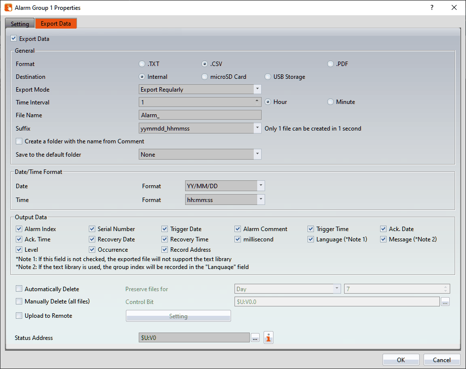
Figure 135【Export Data】Setting Screen of【Alarm】
Table 61【Export Data】Setting Properties of【Alarm】
|
Property |
Description |
||||||||||||||||
|
【Export Data】 |
Set to enable the export function of the alarm data. Export setting items will appear below once this option is selected. |
||||||||||||||||
|
【General】 |
【Format】 Set the format of the export file; TXT file , CSV file or PDF file can be selected. 【Destination】 Set the destination of the exported file: internal, microSD card or USB storage device can be selected. If the output destination is internal storage, you can use FTP to connect to the HMI to read the stored file. 【Export Mode】 Set the time to export the file. If【Export Regularly】is selected, the alarm occurrence data saved by【Alarm】will be exported according to a set interval. If【Triggered by Bit】is selected, the alarm occurrence data saved by【Alarm】will be exported when the set bit is triggered. 【Time Interval/Trigger Bit】 Depending on the export method, you can select export conditions here. 【File Name】 Set the name of the exported file; the file name of the exported file name includes the date and time the file was saved (for example: Alarm_140519_151735.txt). 【Suffix】 Set the name of the exported file, such as yymmdd_hh, the name of exported file only dates and hours (Example: DataLog_140519_17.txt) This setting also provides export archive mode, If the suffix selected is "yymm", it would produce one file per month, If the suffix selected is "yymmdd", it would produce one file per day, If the suffix select "yymmdd_hh", it would produce one file per hour, If the suffix selected is " yymmdd_hhmm", it would produce one file per minute, If the suffix selected is " yymmdd_hhmmss", it would produce one file per second, If the suffix to select "no", one file includes all data. 【Create a folder with the name from comment】 If this option is checked, the name of the folder will be name from【Setting】【Comment】, for example, comment temperature, the original Group_1 folder will be changed to the temperature folder, which is originally alarm \ Group_1 will become alarm \ temperature. 【Save to the default folder】 There is none and folder created monthly two opitons, if choose none then will not create another folder, for example, alarm \Group_1\ Alarm _170403. csv. if choose folder created monthly then will create another monthly folder each month, for example, alarm \Group_1\201704\ Alarm _170403.csv. 【PDF Setting】 When the export format is set to PDF, clicking Settings allows you to adjust the PDF document style. |
||||||||||||||||
|
【Date/Time Format】 |
【Date】 Set the display format of the date when exporting file. 【Time】 Set the display format of the time when exporting file. |
||||||||||||||||
|
【Output Data】 |
【Output Data】allows you to choose which items to export. You can select whether the export file will contain the alarm index, serial number, trigger date, alarm annotation, trigger time, confirmation time, recovery time, message, level, number of occurences, and record address. |
||||||||||||||||
|
【Automatically Delete】 |
Check if you want to automatically delete the exported file. 【Preserve files for】 For example, if you set 7 days, the HMI will check whether there are files over 7 days according to the calendar in the early morning of each day, and those files will be deleted. |
||||||||||||||||
|
【Manually Delete (all files)】 |
Set the control bit to delete the files manually. 【Control Bit】 Set a bit as trigger control, delete when on, and automatically turn back to off after finish deleting. |
||||||||||||||||
|
【Upload to Remote】 |
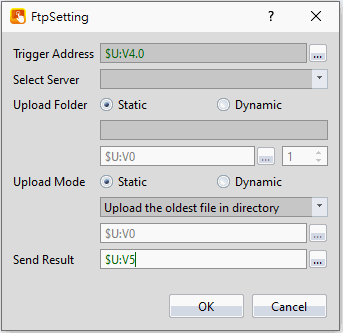
Enable ch4.5-【FTP Client】function then this option can be seen.
【Trigger Address】 Set a bit to trigger uploading. 【Select Server】 Click the drop-down menu to select the server to upload 【Upload Folder】 Fill in the path where the remote server is stored, if not filled in, it will be stored in the root directory of the server 【Upload mode】 There are 7 upload modes for【Static】, which will be described together with【Dynamic】below
【Send Result】 Set the address of the execution result display, the data type is【INT】, Success: 1 / Failure: -1 |
||||||||||||||||
|
【Status Address】 |
Set the save address for error codes.
|
8.3 Alarm Application Example
This section explains the application examples of the【Alarm】function and its setting procedure.
8.3.1 Enabling SMTP
To send emails, first enable the SMTP feature. Go to the System menu on the left side of FvDesigner and select Server.
For detailed settings, refer to section 4.3【SMTP】
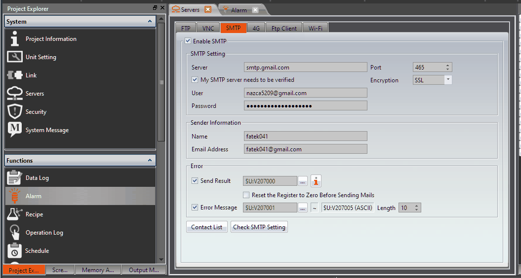
Figure 136【SMTP】Setting window
8.3.2 Configuring Email Sending
In Advanced Settings, check Enable Email Sending.
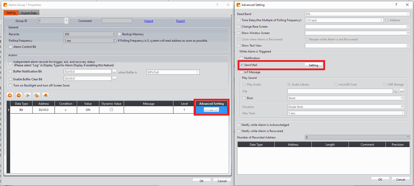
Figure 137 Enable Email Sending
8.3.3 Setting Up Email Content
Set the recipient group (click Contacts to configure), check the information to be attached, add a description, and save it.
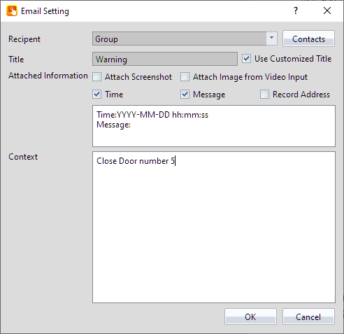
Figure 138 Set Email Content
8.3.4 Receiving Emails
After downloading the project, emails will be received when an alarm is triggered.
To adjust fixed content (such as time and message text), go to System Messages to set the language used.
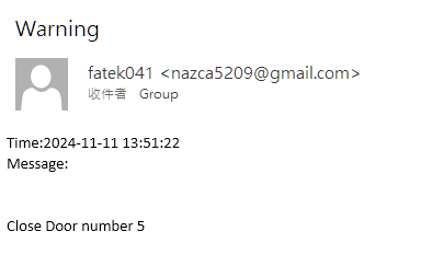
Figure 139 Received Email
8.4 【Sync Data】
Synchronize the alarm data from the database. When enabled, the data will be automatically read from the database when the connection is successful. If you want to view it in the【Alarm Display】, select【Database】in the【Display Type】of the 【Alarm Display】.
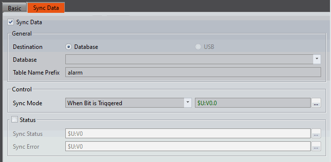
Figure 140【Alarm】【Sync Data】Setting Page
Table 62【Alarm】【Sync Data】Property Setting Page
|
Property |
Description |
||||||||||||||||||||||||||||||
|
【Sync Data】 |
Set whether to enable the data sync function. After enabling, the setting items will appear below. Note: If enable this function, needs to enable serial number as well. |
||||||||||||||||||||||||||||||
|
【General】 |
【Destination】 Set the synchronize destination 【Database】 Set the synchronize database 【Table Name Prefix】 Set the generated table name of the after synchronization. If set name “alarm” as the figure above, then will generate two tables: alarm_data and alarm_data_format.
Note: When the Alarm setting has changed (but the table name is not changed), after downloading to the HMI, the synchronized data table in the database needs to be deleted first then the new alarm will take effect. |
||||||||||||||||||||||||||||||
|
【Control】 |
【Sync Mode】 Set the timing of synchronizing data to the database, including When Buffer is Full, When Bit is Triggered, Daily Synchronization, and Sync Regularly. |
||||||||||||||||||||||||||||||
|
【Status】 |
【Sync Status】 Set the storage address of the status
【Sync Error】 Set error code storage address
|
Tip: press ← → to switch chapters, Ctrl+K to search