22.1 【File Transfer】
【File Transfer】allows the user to transfer files from the computer to the HMI or vice versa via USB connection. To use the【FTP Transmission Function】, please refer to Chapter 4.1 –【FTP Server】for instructions.
The operation flow of【File Transfer】will be described in detail below.
You can open the file transfer function window by clicking File Transfer on the Tools tab of the FvDesigner taskbar.
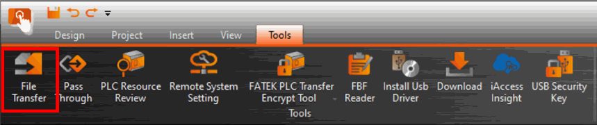
Figure 433【File Transfer】
Click【File Transfer】, the window that pops up is the file transfer function.
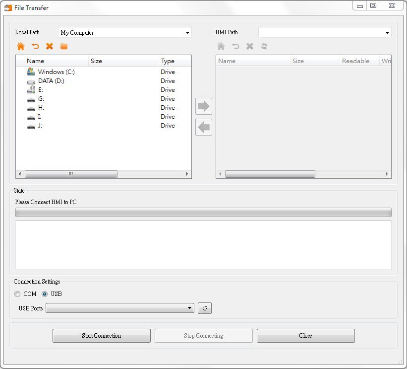
Figure 434【File Transfer】Window
Tabel 268【File Transfer】Button descriptions
|
Field |
Description |
|
【Connection Settings】 |
【COM】 Do the file transfer through COM port. 【USB】 Do the file transfer through mini-USB port. |
|
【Start Connection】 |
When the computer is connected to the HMI via USB, the user can press start connection to start the file transfer. |
|
【Stop Connecting】 |
To end the file transfer, press【Stop Connecting】. |
|
【Close】 |
Same function as【Stop Connecting】,but also close the window afterwards. |
Open【Remote System Setting】and connect to your HMI device. Click MISC, enable the remote password setting, and set a password. Now, when performing the【File Transfer】function, the user will be prompted to enter the password in order to complete the transfer.
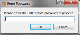
Figure 435【File Transfer】Password Prompt Window
After connecting to the HMI successfully, you will see the following window.
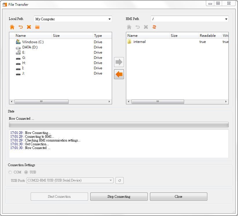
Figure 436【File Transfer】Successful Connection Window
Table 269【File Transfer】After Connecting
|
Field |
Description |
|
【Local】 |
【Local Path】 Displays current computer path 【Home】 Click this icon 【Previous Page】 Click this icon 【Delete】 Click this icon 【Select Location】 Click this icon
Press the right mouse button on a file to to display the menu below
【Enter Folder】 Click this icon 【Add New Folder】 Click this icon
【Download】 Click this icon 【Delete】 Click this icon 【Rename】 Click rename to change the name of a file or folder. |
|
【HMI】 |
【HMI Path】 Displays current HMI path. 【Home】 Click this icon 【Previous Page】 Press this icon 【Delete】 Click this icon 【Refresh】 Click this icon Press the right mouse button to view the menu below.
【Open Folder】 Click this icon 【Add a new folder】 Click this icon
【Upload】 Click this icon 【Delete】 Click this icon 【Rename】 Click rename to change the selected folder name. |
|
【Transmission】 |
【Download】 Click this icon 【Upload】 Click this icon You can also perform these two tasks by simply dragging the desired item to the other directory. |
 to return to My Computer(home page).
 to return to the previous path.
 to delete the local archive.
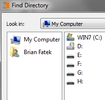
 to jump out of the window and easily select the desired local folder.
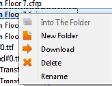
 enter the currently selected folder.
 to create a new folder in the selected location.
 to download selected files to the HMI.
 to delete the selected file.
 to go back to the home page.
 to go back to the previous path.
 to delete the selected HMI file.
 to refresh the current server-side folder information.
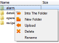
 to open the selected folder.
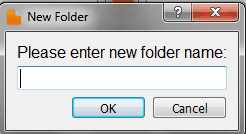
 to add a new folder and enter the folder name, as shown in the window below.
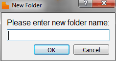
 to upload the selected file to the local directory.
 to delete the HMI file.
 to download the selected files to the HMI.
 to upload the selected files to the local directory (computer).
After successfully connecting the computer and the HMI, the files are ready to be transferred. A datalog transfer will be similar to the image below.
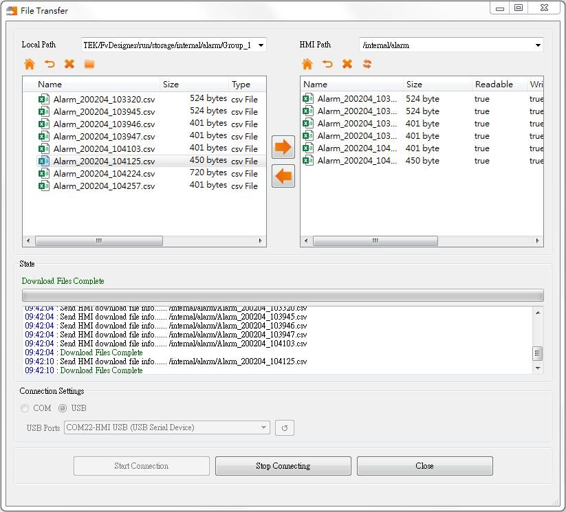
Figure 437【File Transfer】Download File Complete
22.2 【Pass Through】
Pass Through is communication between a PLC and PC through the HMI.
Generally, when the PC wants to perform serial communications with the PLC, related application programs such as WinProLadder (Fatek PLC programming software), is used on the PC and communicates directly with the PLC through the【Ethernet】or the COM port/USB on the PC. However, under some circumstances, the PC cannot connect to the PLC directly or connection information with the PLC cannot be acquired directly. The【Pass Through Function】is provided for such conditions so that the PC can perform serial communications with the PLC indirectly, and also acquire the register data of the device. The communication mode is as shown in Figure 438 Pass Through architecture.
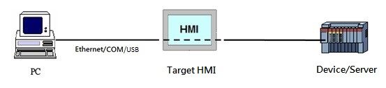
Figure 438 Pass Through architecture
22.2.1 Setting Pass Through
To use pass through, users must first use the FvDesigner to connect to the HMI that they want to pass through and switch it to【Pass Through Mode】. The goal of this action is to tell the HMI to change its operating mode in preparation to be used for【Pass Through】. After successfully setting the HMI to the pass through mode, the HMI will be able to transfer all data coming from the specific port of the PC to the specified PLC.
After the setup, users can use the WinProLadder or other related applications to specify the same port to communicate with the HMI. Although the PC is not directly connected to the PLC, the HMI will transfer all data received from the specified port to the PLC. Therefore in terms of behavior, the result will be the same as connecting directly to the PLC. When the task is complete, FvDesigner can be used again to switch HMI back to the normal operation mode.
The following are detailed descriptions of the【Pass Through】operating process.
The Pass Through function can be launched by clicking on the【Pass Through】icon in the【Tools】function tab of the FvDesigner task bar to open the function window.
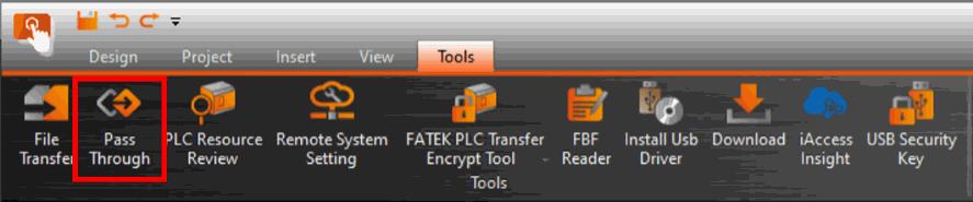
Figure 439【Pass Through】
The dialog that appears after pressing【Pass Through】is the main operating inter-face of the【Pass Through】function. Parameters that can be set include three major categories that correspond to the individually related parameters of PC, HMI and PLC, respectively. For the PC side, the serial port to be used by the HMI can be set (can only be set when the serial port communication is selected). For the HMI side, its IP address, the input COM used to receive data from the PC side and the output COM used to send the data to the PLC side can be set. For the PLC side, related parameters used can be set for the serial communication between the PLC and the HMI.
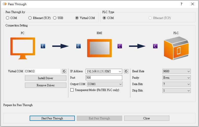
Figure 440 Pass Through parameter setting page
Detailed descriptions of each parameter are as follows:
Table 270 Pass Through related parameters
|
Property |
Description |
|
【Pass Through by】 |
【COM】 Use the serial port to communicate between the PC and the HMI. 【Ethernet (TCP)】 Use Ethernet to communicate between the PC and the HMI. 【USB】 Use USB to communicate between the PC and the HMI. 【Virtual COM】 Before the computer and the HMI communicated through the network, the HMI and the terminal device communicated through the serial port. |
|
【PLC Type】 |
【COM】 Use the serial port to communicate between the HMI and the PLC. 【Ethernet (TCP)】 Use Ethernet to communicate between the HMI and the PLC. |
|
【Connection Setting】 |
【PC】
【HMI】
【PLC】
|
|
【Start Pass Through】 After setting the【Connection Setting】related parameters, press【Start Pass Through】to perform pass through. 【End Pass Through】 To end pass through, press【End Pass Through】on the PC or HMI. 【Close】 This function is the same as【End Pass Through】; It will also close the dialog window after ending pass through. |
 】button after this field to refresh IP address list or manually input an IP address.
 】to get all available serial ports on the target HMI. When the【Ethernet (TCP)】is selected for【Pass Through by】, this field will be locked and unavailable for use.
 】to get all available serial ports on the target HMI; The scan results will be displayed in this pull-down menu.
 】button after this field to refresh IP address list or manually input an IP address.
22.2.2 Pass Through Example
The following shows a simple example for performing pass through Ethernet using WinProLadder (Fatek PLC programming software).
As described in the previous section of this chapter, FvDesigner must be used to connect to the HMI to pass through in order to use the HMI. Its operating mode must be switched to【Pass Through Mode】so that the HMI can transfer the data received from the specified port to the specified Output COM. In order to achieve this goal, first open the FvDesigner and click on the【Pass Through】function,
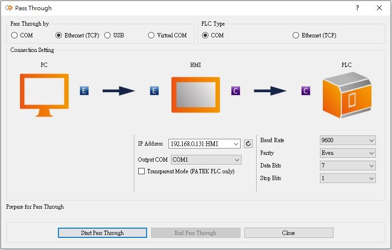
Figure 441 Pass Through parameter setting interface
then select the【Ethernet】as the connection method since the PC will not be connected to the HMI through the serial port. The HMI【Output COM】must still be set.
The user must first press the【 】after the【IP Address】field to get all HMI IP address on the network those are available for pass through, or enter an IP manually. The user must know which serial port is used by the HMI to connect to the PLC, else the pass through function will not be able to operate.
Next, the user must set the related parameters of the serial port used with the PLC. Please note that if the parameters set here are not correct for this PLC, it is likely for unexpected communication failures to occur.
After setting all the parameters, press【Start Pass Through】to switch the target HMI to pass through mode to facilitate the follow-up actions. If the HMI was successfully switched to pass through mode, the status of the operating inter-face will change as shown in the figure below. The status field will show that the HMI was successfully changed to pass through mode.
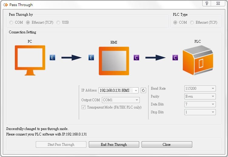
Figure 442 Successfully switched HMI to Pass Through mode
At this time all pre-procedures are completed and the HMI is ready to transfer data between the PC and PLC at any time. User can open the WinProLadder and select【PLC】🡪【Connect】
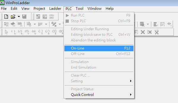
Figure 443 Open WinProLadder connection settings
Connection-related options will appear after clicking. The communication between the PC side and the HMI side in this pass through is through the 【Ethernet】. Therefore, select FATEK-TCP for the connection name.
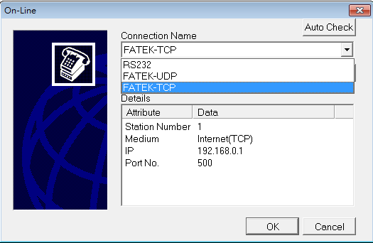
Figure 444 Selecting the communication protocol
The TCP connection-related parameters can be set after pressing Edit, as shown in the figure below:
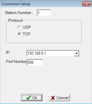
Figure 445 Setting the WinProLadder Ethernet communication parameters
Users need to specify IP address of the HMI, which is going to pass through to the PLC. After configuration is completed, the user can press the OK button to perform pass through.
Note: When using Pass Through function, if the PLC is Fatek HB1, and HMI communicates with the PLC via PLC Port, the baud rate needs to set at 115200 in WinProLadder. .
22.2.3 Virtual COM Passthrough Setting
For the needs of connecting devices that want to passthrough to the serial port through the network, we provide a virtual COM function so that users can choose to use the serial port for connection on the PLC software. Currently, this function supports Windows 7 ( including) operating systems and above.
The following picture shows the screen of selecting virtual COM.
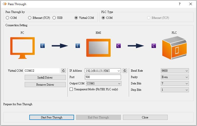
Figure 446 Virtual COM
The driver of the virtual COM will be installed when FvDesigner is installed, and the passthrough communication tool will automatically detect the location of the com port.
If it is not detected or there is a need to remove and reinstall, you can press Install Driver or Remove Driver to operate.
It should be noted that the setting of the port should be the same as the passthrough communication port on the HMI, as shown in the figure below
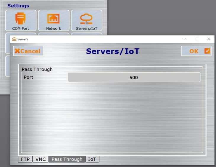
Figure 447 HMI Passthrough Port
22.3 【PLC Resource Review】
The【PLC Resource Review】function can be used if the user needs information on the PLC driver versions supported by FvDesigner or internal PLC single point and register information. The【PLC Resource Review】function allows users to find related information.
This chapter will explain【PLC Resource Review】related pages and the usage.
22.3.1 Usage Methods
Select【PLC Resource Review】in the【Tools】page of the【Ribbon】and the following window will appear.
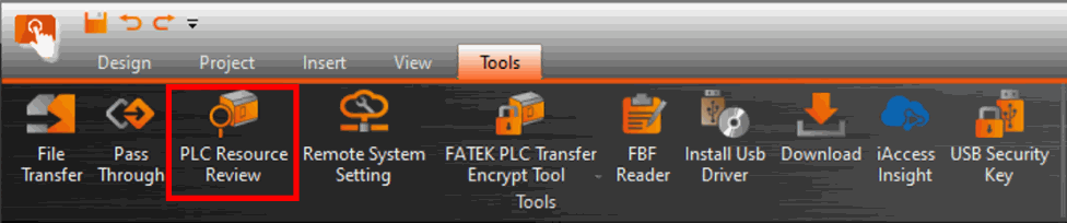
Figure 448【PLC Resource Review】
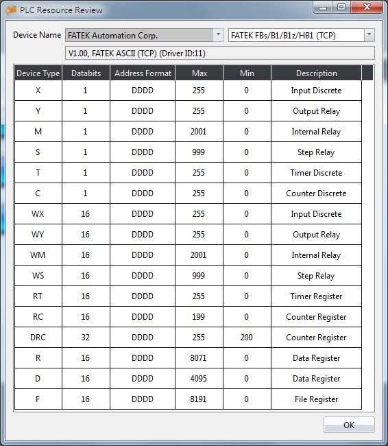
Figure 449 PLC Resource Review
The PLC manufacturer and series model can be selected at the top half of the【PLC Resource Review】as shown in the figure below.

Figure 450 PLC Resource Review–Select PLC manufacturer and series model
Information on the supported PLC driver versions, internal PLC single point, and registers is available for access will appear when the selection is complete, as shown in the figure below.

Figure 451 Information of supported PLC driver versions
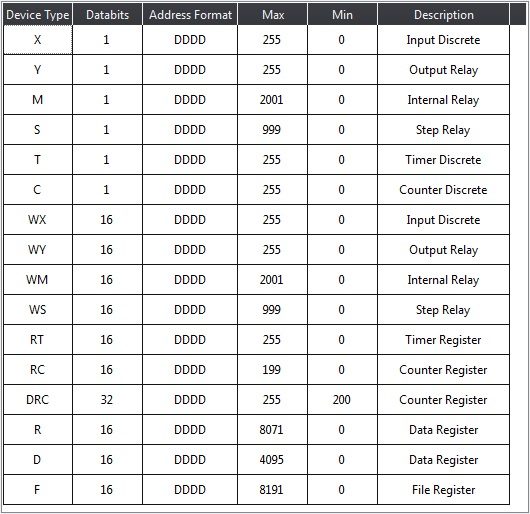
Figure 452 Information on internal PLC single point and registers available for access
Introduction to the internal PLC single point and registers available for access is as shown in the table below.
Table 271 Introduction to internal single point and register information
|
Name |
Description |
|
【Device Type】 |
Represent the code of the single point or register in the PLC. |
|
【Data Bits】 |
Represent the number of bits occupied by the data of this【Device Type】. |
|
【Address Format】 |
Represent the address format that must be used to access this【Device Type】. |
|
【Max】 |
Represent the maximum value of the address range available for access for this【Device Type】. |
|
【Min】 |
Represent the minimum value of the address range available for access for this【Device Type】. |
|
【Description】 |
Describe the function and usage of the【Device Type】. |
22.4 【Remote System Setting】
Users can remote the HMI’s system setting to modify the settings.
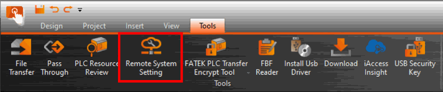
Figure 453【Remote System Setting】
22.4.1 Usage Method
Users need to set up the HMI’s IP before doing connection. After connect successfully users can directly modify the settings, but【Link】and【Calibration】were unable to do. More details please refer to ch24-HMI System Settings.
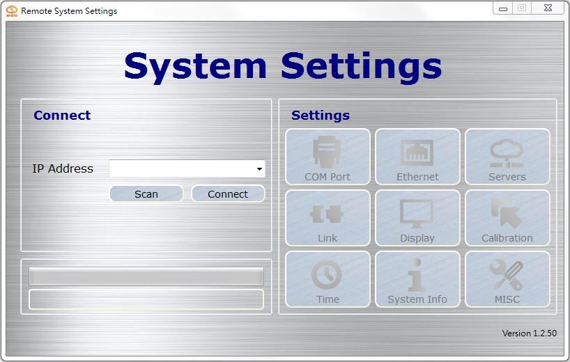
Figure 454【Remote System Setting】setting page
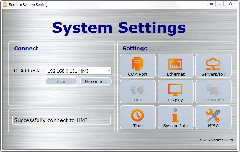
Figure 455【Remote System Setting】successfully connect to HMI
22.5 【FATEK PLC Transfer Encrypt Tool】
This function is that when the user uses the HMI’s USB storage device to update the linked FATEK PLC ladder diagram program, the operation can be protected, thereby protecting the PLC ladder diagram program and intellectual property planned by the designer. More details please refer to ch27.3-【FATEK PLC Transfer Encrypt Tool】
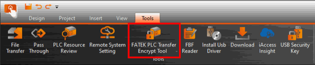
Figure 456【FATEK PLC Transfer Encrypt Tool】
22.6 【FBF Reader】
【FBF Reader】is used when reading the *.FBF file of the FATEK’s own format or when converting a *.FBF file to another file format. It can be converted to a *.TXT file, *.CSV file, or *.PDF file. For how to generate *.FBF files, please refer to chapter0-
【Export Data】 .
The following will explain in detail the operation flow of【FBF Reader】.
FBF Reader function Click【FBF Reader】on the【Tools】tab on the ribbon to open the function window.
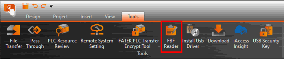
Figure 457【FBF Reader】
After selecting【FBF Reader】, the popup dialog box is the main operation interface of【FBF Reader】function, as shown below.
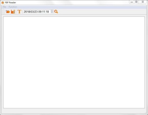
Figure 458【FBF Reader】function dialog
Tabel 272【FBF Reader】menu descriptions
|
Properties |
Description |
|
【File】 |
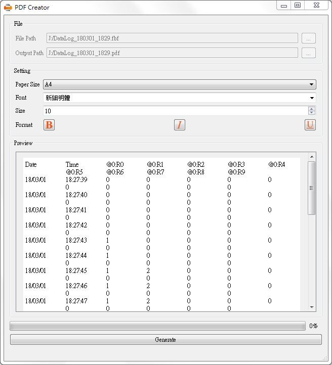
【Open】 Open FATEK’s own format *.FBF file. 【Save as】 After reading FATEK’s own format *.FBF file, save as *.TXT file, *.CSV file or *.PDF file, etc. Save as new file if choose to save as PDF, the following dialog will appear, you can set the font type, size and format. Press the【Generate】button to convert the *.FBF file to a PDF file. 【Quit】 Leave and close the FBF Reader. |
|
【Function】 |
【Font Setting】 Adjust the font size to the display *.FBF file in FATEK’s own format. |
Tabel 273【FBF Reader】tool bar descriptions
|
Icon |
Description |
|
|
【Open】 Open FATEK’s own *.FBF file. |
|
|
【Save as】 After reading FATEK’s own format *.FBF file, save as *.TXT file, *.CSV file or *.PDF file, etc. |
|
|
【Font Setting】 Adjust the font size to the display *.FBF file in FATEK’s own format. |
|
|
Set the date and time to search for FBF files. |
|
|
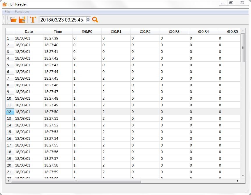
Search, set the date and time to search the FBF file and press this button, the cursor will be displayed in this column, as shown below.
|




22.7 【Install USB Driver】
The FvDesigner can do the connection with HMI by using mini-USB cable, to install the driver to make sure the function work.
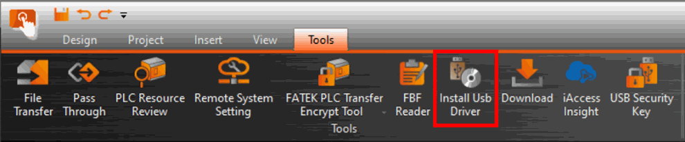
Figure 459【Install USB Driver】
22.8 【Download】
The download function in【Tools(T)】is the same as the download function in 【Project(P)】. For detailed operations, please refer to chapter 21.1.1-Download the running package and operating system from a PC . In【Tools(T)】,the download can choose the running package (.cfrp)
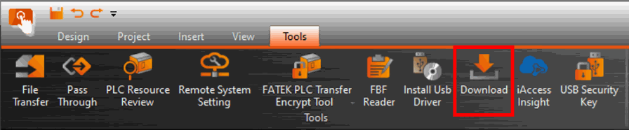
Figure 460【Download】
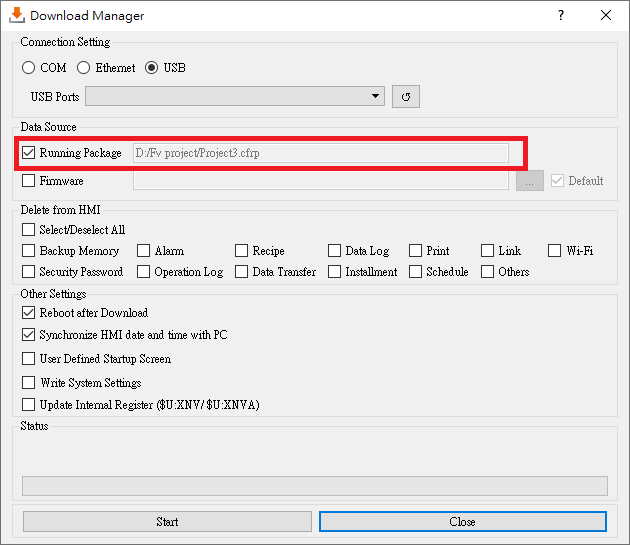
Figure 461【Download】setting page
22.9 【iAccess insight】
This function needs to login to the FATEK cloud, provides project upload, download, and remote.
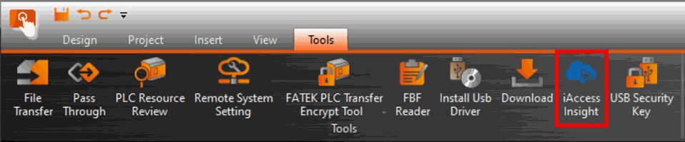
Figure 462【iAccess】
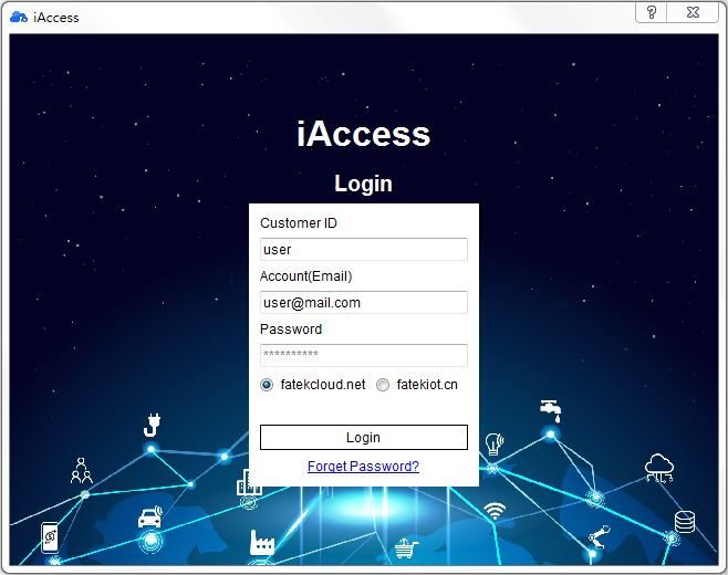
Figure 463【iAccess】login page
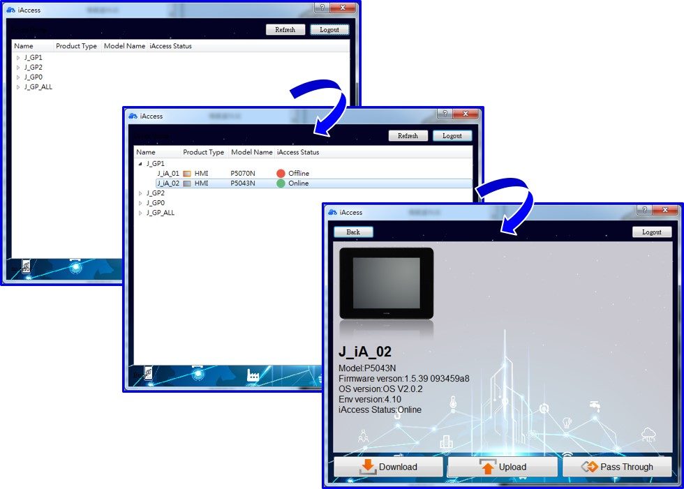
Figure 464【iAccess】operation page
Tip: press ← → to switch chapters, Ctrl+K to search