21.1 【Download Current Project】
When a running package (.cfrp) has been successfully built and had no errors during simulation, it is ready to be downloaded to the HMI. Fatek provides diverse download methods. Users can download the running package from the PC to the HMI through a serial port connection, Ethernet connection or by using a USB cable.
21.1.1 Download the running package and operating system from a PC
The download function can be found in the【Project】function tab on the ribbon taskbar on top of the FvDesigner. Click on【Download Current Project】and a dialog window will open and enter the【Download Manager】setting screen.
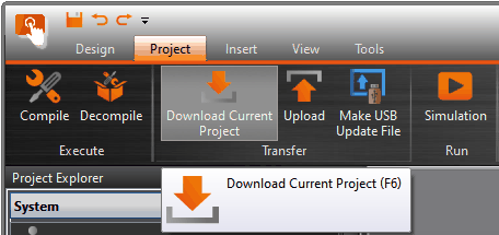
Figure 401 Open download function
The following are detailed descriptions for the【Download Manager】.
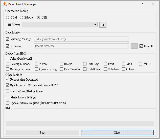
Figure 402 Download Manager function interface
Table 256 Download Manager–related parameters
|
Property |
Description |
|
【Connection Setting】 |
【COM】 Select to perform download through the serial port; the port number used for downloading must also be specified when this option is selected. 【Ethernet】 Select to perform download through the Ethernet. The IP address of the target HMI must also be specified when this option is selected. Press【Scan】on the right to acquire the HMI IP addresses and device names currently online. Users can also manually enter the IP address of the target HMI to perform download. Note: The Scan button may have no effect under certain network environments (usually when the DHCP server cannot accurately configure the IP addresses). In this case, the command prompt can be opened to execute the following commands in sequence to restore the function.
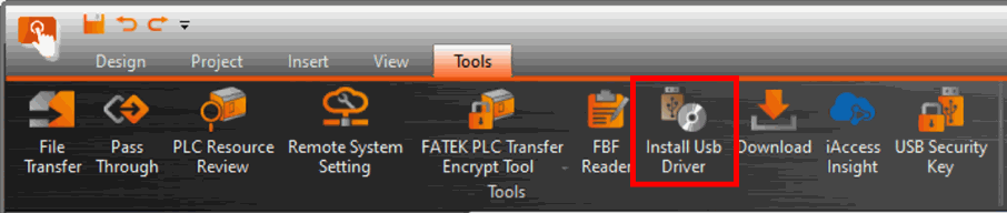
Please re-start the computer when completed for the settings to take effect. 【USB】 Perform download through USB. The default path of USB Driver is under C:\Program Files\Fatek\FvDesigner\Ver1.6\usb driver The USB drivers can be installed by clicking【Install USB Driver】in the【Tools】tab.
|
|
【Data Source】 |
【Running Package】 Download the current rinning package, if want to download other running package, go to the Tools page to do download. 【Firmware】 The HMI firmware will be downloaded once this option is selected. The default path of【Firmware】is under (Under 64-bit Windows) C:\Program Files (x86)\FATEK\FvDesigner\Ver1.6\application \firmware\FvFirmwareC.frt (Under 32-bit Windows) C:\Program Files\FATEK\FvDesigner\Ver1.6\application \firmware\FvFirmwareC.frt |
|
【Delete on Target】 |
This field determines whether to clear the existing data saved on the HMI: 【Select/Deselect All】 After checked, all the following options will be checked. If not checked, all items below will be unchecked. 【Backup Memory】 If this option is selected, the data stored in the HMI’s non-volatile memory will be deleted when the download process starts. 【Alarm】 If this option is selected, the existing alarm log on the HMI will be deleted when the download process begins. The HMI will clear all files under /internal/alarm/. 【Recipe】 If this option is selected, the existing recipe files on the HMI will be deleted when the download process begins. The HMI will clear all files under /internal/recipe/. 【Data Log】 If this option is selected, the existing data log on the HMI will be deleted when the download process begins. The HMI will clear all files under /internal/datalog/. 【Print】 If this option is selected, the screenshots saved in the HMI internal memory will be deleted when the download process begins. The HMI will clear all files under /internal/hardcopy/. 【Link】 If this option is selected, the program will start the deletion of the original link parameters and replace them with the new link parameters. 【Security Password】 If this option is selected, the password table on the HMI will be deleted when the download process begins. If this option is selected, the original password table will be retained. 【Operation Log】 If this option is selected, the existing operation log on the HMI will be deleted when the download process begins. The HMI will clear all files under /internal/operationlog/. 【Data Transfer】 If this option is selected, the data transfer files on the HMI will be deleted when the download process begins. The HMI will clear all files under /internal/datatransfer/. 【Installment】 If this option is selected, the download process will delete the original installment information and the previously entered records. 【Schedule】 If this option is selected, the download process will delete the original data that has been modified through the【Schedule】on the HMI, so the schedule will based on the project; if not checked, the original data that has been modified through the【Schedule】on HMI will be retained. 【Others】 If this option is selected, all other files on the HMI will be deleted when the download process begins. The HMI will clear all files under /internal/ not including the options detailed above. |
|
【Other Settings】 |
【Reboot after Download】 Set to reboot HMI after downloading project is complete. 【Synchronize HMI date and time with PC】 Set to synchronize the date and time of HMI with PC after downloading project is complete. 【User Defined Startup Screen】 Allows designers to define their own HMI boot screen, such as the title of the company, etc., after the option is checked, you can choose a picture on the PC. After the project download is complete, the HMI boot screen will be changed. Fatek HMI factory boot screen, default location: (Under 64-bit Windows) C:\Program Files (x86)\FATEK\FvDesigner\Ver1.6\startup screen (Under 32-bit Windows) C:\Program Files\FATEK\FvDesigner\Ver1.6\startup screen 【Write System Setting】 Providing parameters that can be set to the HMI at the same time when the project downloads, can reduce the tedious setting work, especially when the same project is downloaded to multiple HMI, each of the HMI does not need to enter the system settings screen settings, after checked, select the *.fscfg file on the right, or press the Edit button on the right to edit the *.fscfg file. For details, refer to chapter21.1.2-Write System Setting . 【Update Internal Register($U:XNV/$U:XNVA)】 Download XNV/XNVA register data to HMI, refer to chapter 24.2.10.5-【Backup】. |
|
【Status】 |
Displays the current download status and download progress. 【Start】 Press this switch to start downloading once setting configuration is complete. 【Close】 Press this switch to end downloading and close the download window. |
Note:
If the HMI has been updated to a new version of firmware or the program has update, the files associated with the old version of sotware cannot be used.
21.1.2 Write System Setting
Providing parameters that can be set to the HMI at the same time when the project downloads, can reduce the tedious setting work, especially when the same project is downloaded to multiple HMI, each of the HMI does not need to enter the system settings screen settings, after checked, select the *.fscfg file on the right, or press the Edit button on the right to edit the *.fscfg file. Pressing the【Edit】button on the right will bring up the system setting configuration window as shown in the figure below.
21.1.2.1 【Basic】
【System Setting Configure】【Basic】setting paging as shown below, the meaning of each setting is as follows :
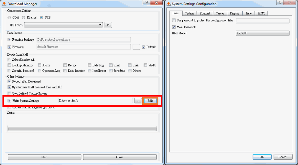
Figure 403【System Setting Configure】【Basic】setting page
Table 257 【System Setting Configure】【Basic】properties setting
|
Properties |
Description |
|
【Basic】 |
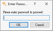
【Use password to protect this configuration files】 Check if you want to set a password to protect this configuration file. If you select it, you can set the password on the right. When you press the【Edit】button on the right again to edit the *.fscfg file, the following figure will appear, requiring a password to continue editing.
【Mask Passwords】 Mask the password of【Use password to protect this configuration files】, default is checked . 【HMI Model】 Select the model you want to set. |
21.1.2.2 【System】
【System Setting Configure】【System】setting paging as shown below, the meaning of each setting is as follows :
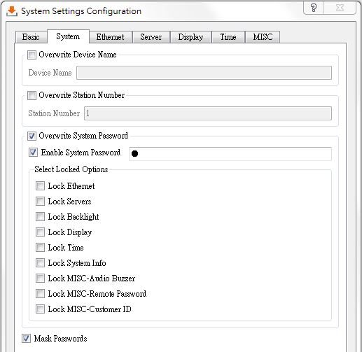
Figure 404【System Setting Configure】【System】setting page
Table 258 【System Setting Configure】【System】properties setting
|
Properties |
Description |
|
【System】 |
【Overwrite Device Name】 Check whether to overwrite the name of the HMI. After checked, the name of the HMI can be edited under【Device Name】. 【Overwrite Station Number】 Check whether to overwrite the station number of the HMI. After checked, the station number of the HMI can be edited under【Station Number】. 【Overwrite System Password】 Check whether to overwrite the system password of the HMI. After checked, the system password of the HMI can be edited under【Enable System Password】. 【Enable System Password】 Check whether to enable the system password of the HMI. After checked, the system password of the HMI can be edited on the right. 【Select Locked Options】 After checked【Enable System Password】, can check the items to be locked in the system settings of the HMI at the bottom, includes【Lock Ethernet】、【Lock Servers】、【Lock Backlight】、【Lock Display】、【Lock Time】、【Lock System Info】、【Lock MISC-Audio Buzzer】、【Lock MISC-Remote Password】and【Lock MISC-Customer ID】. 【Mask Passwords】 Mask the password of【Use password to protect this configuration files】, default is checked . |
21.1.2.3 【Ethernet】
【System Setting Configure】【Ethernet】setting paging as shown below, the meaning of each setting is as follows :
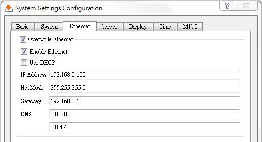
Figure 405【System Setting Configure】【Ethernet】setting page
Table 259 【System Setting Configure】【Ethernet】properties setting
|
Properties |
Description |
|
【Ethernet】 |
【Overwrite Ethernet】 Check whether to overwrite the ethernet setting of the HMI. After checked, the ethernet setting of the HMI can be edited under【Enable Ethernet】. 【Enable Ethernet】 Check whether to enable【Ethernet】on the HMI. After checked, the ethernet IP address or【DHCP】of the HMI can be edited under【Enable Ethernet】. 【Use DHCP】 Check whether to use【Use DHCP】, if【Use DHCP】is checked, the four options of【IP Address】、【Net Mask】、【Gateway】and【DNS】will be turned off and set by the system. |
21.1.2.4 【Sever】
【System Setting Configure】【Server】setting paging as shown below, the meaning of each setting is as follows :
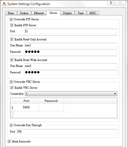
Figure 406【System Setting Configure】【Sever】setting page
Table 260 【System Setting Configure】【Sever】properties setting
|
Properties |
Description |
|
【Overwrite FTP Server】 |
Check whether the HMI FTP server settings are overwritten or not. After checked, select【Enable FTP Server】below and edit other FTP-related settings. 【Enable FTP Server】 Check whether to enable the【Enable FTP Server】function of the HMI. If select it, you can edit the FTP port, user name and password below. 【Port】 Select the port of FTP server to use. 【Enable Read-Only Account】 Check whether to enable read-only account. After checked,you can set the user’s name and password below. 【Enable Read-Write Account】 Check whether to enable read-write account. After checked,you can set the user’s name and password below. |
|
【Overwrite VNC Server】 |
Check whether the HMI VNC server settings are overwritten or not. After checked, select【Enable VNC Server】below and edit other VNC-related settings. 【Enable VNC Server】 Check whether to enable the【Enable VNC Server】function of the HMI. If select it, you can edit the VNC port, and password below. 【Connection】 Set the number of VNC clients that can be connected to this VNC server at the same time. The maximum number of supported devices will vary depending on the model. 【Port】 To set the VNC connection port, you can only set the connection line for the first client. The second line will automatically increase. For example, the first setting is 5900, and the second line is 5901. 【Password】 Enter the password of VNC server. |
|
【Overwrite Pass Through】 |
Check whether to overwrite port of the pass through setting. 【Port】 Set the port the pass through. |
|
【Mask Passwords】 |
【Mask Passwords】 Mask the password of【FTP Server】and【VNC Server】that user edited. |
21.1.2.5 【Display】
【System Setting Configure】【Display】setting paging as shown below, the meaning of each setting is as follows :
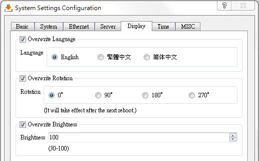
Figure 407【System Setting Configure】【Display】setting page
Table 261 【System Setting Configure】【Display】properties setting
|
Properties |
Description |
|
【Overwrite Language】 |
Check whether to overwrite the language setting of the HMI 【Language】 Select language to overwrite |
|
【Overwrite Rotation】 |
Check whether to overwrite the rotation setting of the HMI 【Rotation】 Select rotation to overwrite Note: Changes will not take effect until the next reboot. |
|
【Overwrite Brightness】 |
Check whether to overwrite the backlight brightness of the HMI. 【Brightness】 Set the backlight brightness of the HMI. |
21.1.2.6 【Time】
【System Setting Configure】【Time】setting paging as shown below, the meaning of each setting is as follows :
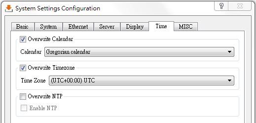
Figure 408【System Setting Configure】【Time】setting page
Table 262 【System Setting Configure】【Time】properties setting
|
Properties |
Description |
|
【Overwrite Calender】 |
Check whether to overwrite the calender setting of the HMI. 【Calender】 Select calender to overwrite. |
|
【Overwrite TImezone】 |
Check whether to overwrite the time zone of the HMI. 【Time Zone】 Select time zone to overwrite. |
|
【Overwrite NTP】 |
Check whether to overwrite the NTP of the HMI. 【Enable NTP】 Check whether to enable NTP. |
21.1.2.7 【MISC】
【System Setting Configure】【MISC】setting paging as shown below, the meaning of each setting is as follows :
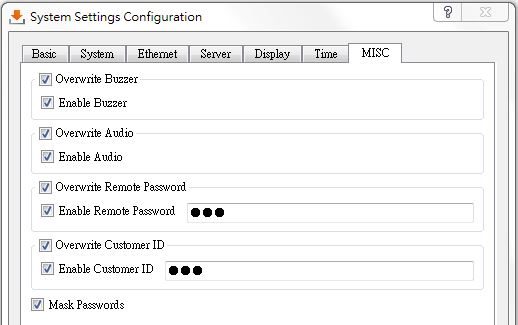
Figure 409【System Setting Configure】【MISC】setting page
Table 263 【System Setting Configure】【MISC】properties setting
|
Properties |
Description |
|
【Overwrite Buzzer】 |
Check whether to overwrite the buzzer setting of the HMI. 【Enable Buzzer】 Check whether to enable buzzer. |
|
【Overwrite Audio】 |
Check whether the audio setting of the HMI. 【Enable Audio】 Check whether to enable audio. |
|
【Overwrite Remote Password】 |
Check whether to overwrite the remote password setting of the HMI. 【Enable Remote Password】 Check whether to enable remote password, set the password on the right. |
|
【Overwrite Customer ID】 |
Check whether to overwrite the customer ID setting of the HMI. 【Enable Customer ID】 Check whether to enable customer ID, set the password on the right. |
|
【Mask Passwords】 |
【Mask Passwords】 Mask the password of【Remote Password】and【Customer ID】that user edited. |
21.1.3 Download Security
If system password is set, HMI will ask user for this password to proceed before downloading. If the project has a set download password, you must enter the correct input cfrp download password to continue to download, if the error is entered, the download will be terminated.
21.1.4 Download Project by USB Flash Drive
The user can make the project into a file that can be downloaded with a USB flash drive, so that the HMI can be easily transplanted to the same type of HMI.
This is very helpful for expanding the same plant but the network or computer equipment is underdeveloped.
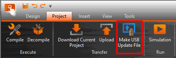
Figure 410 Make USB Update File Function
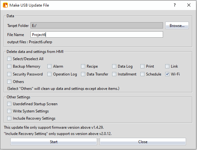
Figure 411 Make USB Update File
There are some points that need to be attended at the follow:
- If the USB size is larger, wait a while, and then the Project Update Question Dialog will appear
- In order to improve the software performance, we have done some software changes, if you are using FvDesigner V1.3.29 previous versions, please pay attention to the use of USB drive ufrp file upgrade project, it may encounter instability, solution please use FvDesigner V1.3.29 or V1.4.7 later to re-download the software, and then use USB drive update project
- V1.3.29 or V1.4.7 later version, the production of USB drive update file, the filename extension is ufrp2, if you do not use FvDesigner V1.3.29 or V1.4.7 or later version of the software downloaded the HMI will not be able to identify V1.3.29 or V1.4.7 or later version, make the USB drive update file, the solution please use FvDesigner V1.3.29 or V1.4.7 later version of the software to re-download
Table 264 Make USB Flash Drive Update File
|
File |
Build Version |
HMI-supported firmware version |
||
|
UFRP |
?-v1.3.28 v1.4.0-v1.4.6 |
?~v1.3.x |
v1.4.0-v1.4.x |
v1.5.0-v1.5.x *OS v1.0 only |
|
UFRP+ |
v1.3.29-v1.3.x |
v1.3.29-v1.3.x |
v1.4.7-v1.4.x |
v1.5.0-v1.5.x *OS v1.0 only |
|
UFRP2v1 |
v1.4.7-v1.4.x |
v1.3.29-v1.3.x |
v1.4.7-v1.4.x |
v1.5.0-v1.5.x |
|
UFERP |
v1.5.3-v1.5.x |
v1.4.29-v1.4.x |
v1.5.3-v1.5.x |
|
Table 265 properties of making USB drive upgrade file
|
Options |
Description |
|
【Data】 |
【Target Folder】 File storage path, you can browse to select the storage path. 【File Name】 Set the file name of the USB drive update file 【output files】 The filename of the output file is .uferp2 |
|
【Delete from HMI】 |
This column determines whether to clear the data originally stored in the HMI. In addition to produce the update file of USB drive, you can choose to clear the original data stored in HMI, through the operation of HMI, insert the USB drive will appear USB project update list dialog, you can also select from delete item, once selected, it will delete the select item when the project download complete. 【Select All】 After checked,【Backup Memory】、【Alarm】、【Recipe】、【Data Log】、【Print】、【Link】、【Security Password】、【Operation Log】、【Data Transfer】、【Installment】、【Schedule】and【Others】all of them will be selected. 【Backup Memory】 After checked, it will delete the HMI internal data after USB drive updated HMI file. 【Alarm】 After checked, it will delete the HMI origin alarm record after USB drive updated HMI file. That is, all files under the HMI / internal / alarm / 【Recipe】 After checked, it will delete the HMI origin recipe file after USB drive updated HMI file. That is, all files under the HMI / internal / recipe / 【Data Log】 After checked, it will delete the HMI original data log record after USB drive updated HMI file. That is, all files under the HMI / internal / datalog / 【Print】 After checked, it will delete the HMI origin print data after USB drive updated HMI file. That is, all files under the HMI / internal / hardcopy / 【Link】 After checked, it will delete the HMI original parameters through the system parameters set communication after USB drive updated HMI file. That is, the controller communication reset the parameter accordind to the connection on the software 【Security Password】 After checked, after USB drive updated HMI file will delete the HMI origin password table, at this point, if the project has set the password table, the password table will be the main in the project; if unchecked will retain the origin password table that on the HMI. 【Operation Log】 After checked, it will delete the HMI origin operation log after USB drive updated HMI file. That is, all files under the HMI / internal / operationlog / 【Data Transfer】 After checked, it will delete the HMI origin transfer data after USB drive updated HMI file. That is, all files under the HMI / internal / datatransfer / 【Installment】 After checked, and after the USB flash drive update the HMI file then the origin installment data will be deleted. For example, if there are 3 periods and 2 periods have been entered, then the record will be deleted if the intallment option is checked. 【Schedule】 After checked, it will delete the original schedule information on the HMI after USB flash drive updates the HMI data. Such as the project originally set start at 8:00:00, change to start at 9:00:00 during the HMI executing. If didn’t check this option, it will remain startup from 9:00:00, if did check this option, it will delete the modified record, and stratup from 8:00:00. 【Others】 After checked, except the above files on the HMI will be deleted after update the HMI file. Indicates that all the files under other folders on the HMI internal path /internal/ will be deleted. |
|
【Other Settings】 |
【Userdefined Startup Screen】 Allows user to set the HMI start up screen. A start up screen could be the company logo, a log in screen, etc. Once the USB update is complete, the HMI boot screen will be changed. The Fatek HMI boot screen is in the given location: (under 64bit windows) C:\Program Files (x86)\FATEK\FvDesigner\Ver1.5\startup screen (under 32bit windows) C:\Program Files\FATEK\FvDesigner\Ver1.5\startup screen 【Write System Setting】 This allows designers after update HMI via USB flah drive, whether to modify the HMI system setting at the same time, so that it is not necessary for each HMI to enter the system setting adjustment when updating multiple HMIs. For more details, please refer to chapter21.1.2-Write System Setting. 【Include Recovery Settings】 When checked, the needed data to recovery the system will be packaged into the USB flash drive to update the file, so that the user can use the USB flash drive to repair the HMI. For details, please refer to chapter 21.1.2-Write System Setting. Note: If the user selects this option, select it in【Project Information】【Security】at the same time 【Enable Download Password】will fail to package. |
|
【Start】 When finished adjusting your settings, press start to begin the update. 【Close】 Press this button to end and close the window. |
When plugging the USB flash drive into the HMI with the .uferp file, the HMI will display the following dialogue. Select the file to update.
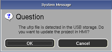
Figure 412 Project Update Question Dialog
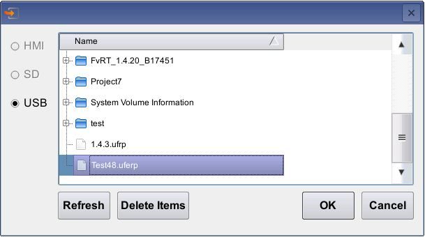
Figure 413 USB Update List
21.2 【Upload】
Users can upload the running package (.cfrp) saved on the HMI, which includes the project, recipes, fonts, etc. onto the computer so that users can easily transfer the running package onto different HMIs. This is helpful in situations such as when expanding similar plants, where network or computer equipment is limited.
21.2.1 Uploading running package to a computer from the HMI
The upload function can be found in the【Project】function tab on the ribbon taskbar on top of the FvDesigner. Click on【Upload】and a dialog window will open and enter the【Upload Manager】setting screen.
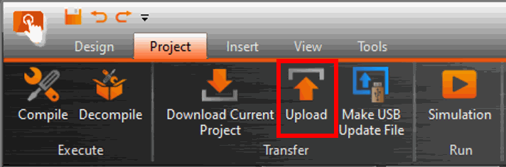
Figure 414 Open the upload function
The following are detailed descriptions for the【Upload Manager】.
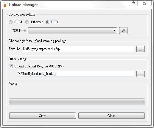
Figure 415 Upload Manager function interface
Table 266 Upload Manager-related parameters
|
Properties |
Description |
|
【Connection Setting】 |
【COM】 Select to perform the upload through the serial port. The port number used for uploading must also be specified when this option is selected. 【Ethernet】 Select to perform the upload through the Ethernet. The IP address of the target HMI must also be specified when this option is selected. Press【Scan】on the right to acquire the HMI IP addresses and device names currently online. Users can also manually enter the IP address of the target HMI to perform the upload. Note: The Scan button may have no effect under certain network environments (usually when the DHCP server cannot accurately configure the IP addresses). In this case, the command window can be opened to execute the following commands in sequence to restore the function.
Please re-start the computer when completed for the settings to take effect. 【USB】 Perform the upload through USB. The USB Driver is under the FvDesigner installation path. The default USB Driver is under the C:\Program Files\Fatek\FvDesigner\Ver1.6\usb driver data file. You can also click on【Install USB Driver】in the【Tools】tab of the ribbon to install directly.
|
|
【Choose a path to upload running package】 |
【Save To】 Specify the storage path after the running package is uploaded. |
|
【Other settings】 |
【Upload Internal Register ($U:XNV)】 Upload HMI’s XNV register data as well. |
|
【Status】 |
Displays the current upload status and upload progress. 【Start】 Press this switch to start uploading once setting configuration is completed. 【Close】 Press this switch to end uploading and close the upload window. |

21.2.2 Upload Step
The upload step example will using mini-USB:
Step 1: Switch to Project(P), then click “Upload”
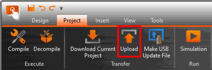
Figure 416 Upload Step 1
Step 2: Connection Setting select “USB”, if the drop-down menu didn’t show any COM port, click the refresh button.
Set the storage path. After uploading, a file with a .cfrp extension will be generated, so you need to set the path of the storage file here. After the setting is completed, press Start to see the progress bar running, and "Please use decompile to get your project" will appear after the end function to get the project.
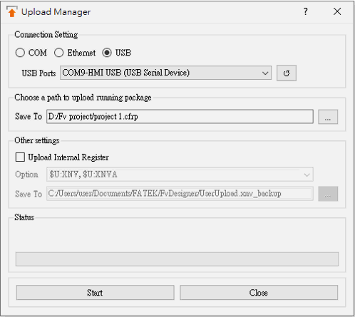
Figure 417 Upload Step 2
Step 3: Go back to the menu on the top row, select decompile, click the browse of the project source to confirm whether the file exists, and then click decompile, and the project file (.fpj) will appear in the folder after the execution is completed.
Note: If the decompiled software version is older than the firmware version of the HMI, it will fail. Please use the latest version of the software.
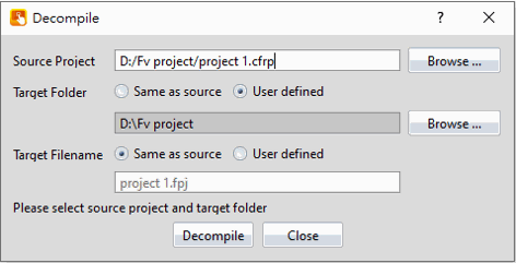
Figure 418 Upload Step 3
21.2.3 Upload Security
If system password is set, HMI will ask user for this password to proceed before uploading. If the project has a set upload password, you must enter the correct input cfrp uppassword to continue to upload, if the error is entered, the upload will be terminated.
21.2.4 Upload Project by USB Flash Drive
When there’s no computer on your hand, but want to get the project from the HMI, you can use USB flash drive to get it.
First, add a folder and named upload, then plug it into the HMI and will ask the user whether to upload the project.

Figure 419 Add upload folder
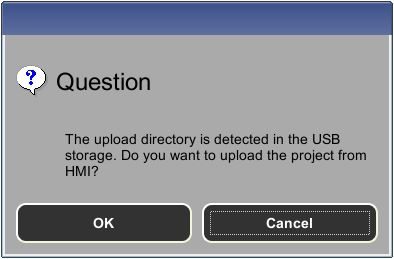
Figure 420 HMI upload asking dialogue
21.3 【Compile】
21.3.1 Compile Introduction
Compile is used to confirm the accuracy of the current plan and also converts the HMI plan project into a running package that can be placed into the HMI. The running package includes settings and the converted language required for the HMI.
The compiling running packages includes the two parts: (1) Starting compilation (2) Checking for errors after compilation is complete. The introduction to these two parts are as follows.
21.3.2 Start compiling running packages
To start compiling, press the【Compile】switch in the【Project】section of the HMI toolbar.
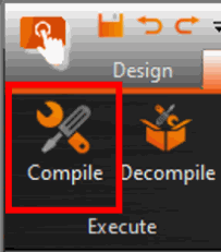
Figure 421 Perform compile from the toolbar above
21.3.3 Ending compile and error check
When the compilation ends, the compile process will be displayed in the【Output Message】below, and a running package (with file extension cfrp, which is short for Compress FATEK Running Package) to be used on the HMI will be generated. This running package can be placed in the HMI for use.
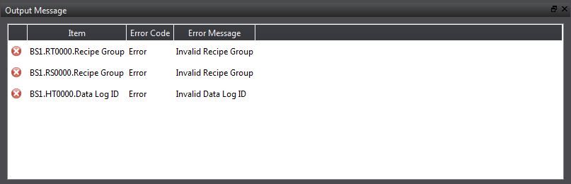
Figure 422 Compilation process illustration
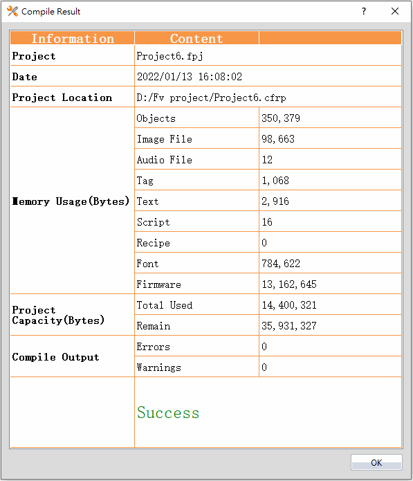
Figure 423 Compilation results illustration
If any errors were generated during the compilation, it will be displayed in the【Output Message】. The error information will include the (1) component, (2) success or error code and (3) compile message as shown in Figure 422. Users can click on the message once to move to the object or double-click on the message to open the error screen and focus on the component setting screen of the error, allowing the user to quickly debug the error.
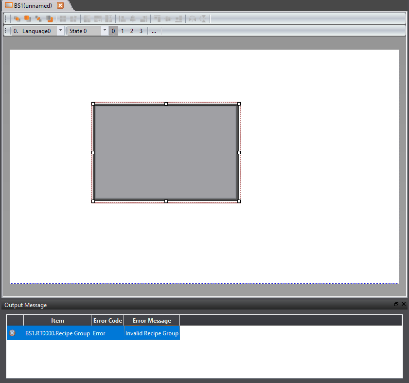
Figure 424 Single click on the compile failure message window to jump to the component
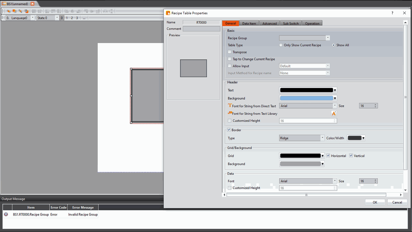
Figure 425 Double click on the compile failure message to open the screen setting
21.3.4 Decompile
The main purpose of the decompile function is to copy the project (.cfrp) from the HMI to the computer or the compiled project (.cfrp) and restore it to the file format (.fpj) so that the FvDesigner software can edit it.
To start the【Decompile】function, press the【Decompile】icon in the Project tab.
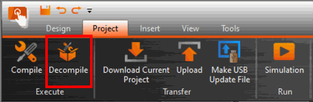
Figure 426 Decompile Function
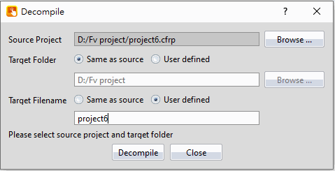
Figure 427 Decompile dialog window
Table 267 Decompile dialog window settings
|
Field |
Description |
|
【Source Project】 |
Specify the path and file for the project source |
|
【Target Folder】 |
Specify the destination path for the generated file from the project decompilation. |
|
【Target Filename】 |
Select whether the file name generated after the decompilation is the same as the project source or determined by the user. |
21.4 【Simulation】
21.4.1 Simulation Introduction
【Simulation】is used to perform preliminary tests before downloading the running package to the HMI in order to reduce the likelihood of finding errors after being downloaded into the HMI. Running simulations can verify the accuracy of the project plan. The simulation function can be run on the PC to simulate how the running package will run on the HMI. Simulations provided by Fatek are divided into【Offline Simulation】and【Online Simulation】. The simulation setting window can be used to determine whether to start the Offline or Online Simulation.
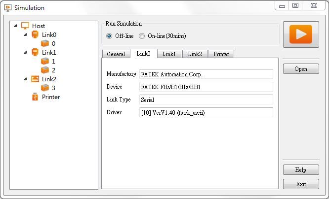
Figure 428 Simulation setting window
21.4.2 Starting Simulation
Users can start【Simulation】by opening the simulation setting window from【Project】, and then selecting whether to perform【Offline Simulation】or【Online Simulation】.
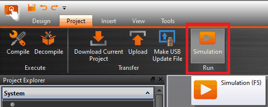
Figure 429 Starting simulation
21.4.3 Offline Simulation
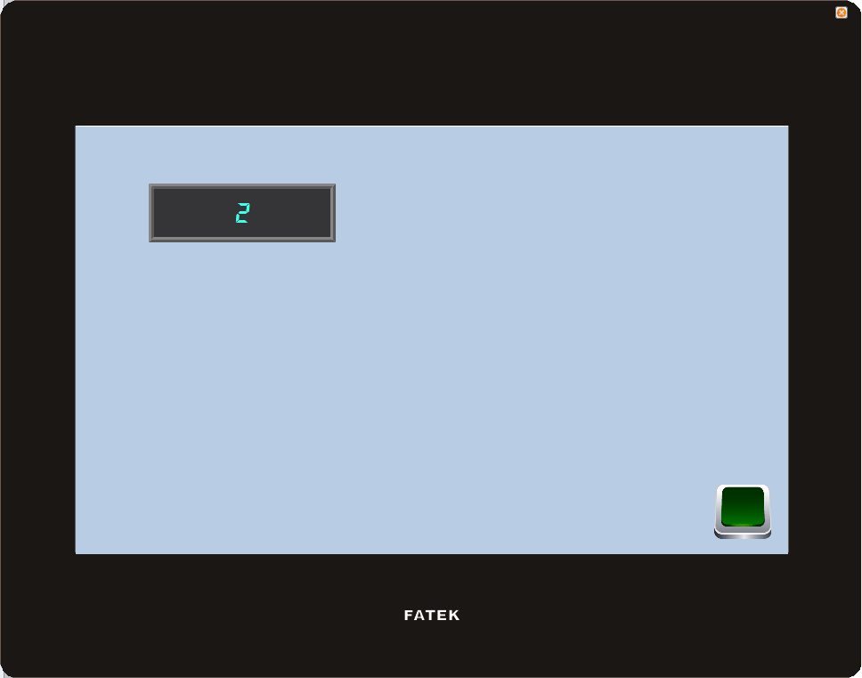
Figure 430 Offline Simulation
【Offline Simulation】is as shown in Figure 430. A simulator will open on the PC and create a virtual PLC that is connected to the HMI in the memory of the PC. Therefore, no communication errors will be generated during the simulated connection. The simulated connection is used to verify the accuracy of the screen and logic.
21.4.4 Online Simulation
The difference between【Online Simulation】and【Offline Simulation】is that the PLC to connect (serial or network connection) can be set. As shown below, Online Simulation can be started when the setting is complete.
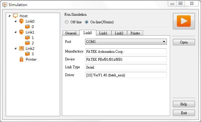
Figure 431 Online simulation connection setting
【Online Simulation】is as shown in Figure 431 Similar to【Offline Simulation】, a simulator is opened on the PC. However, the PC will communicate with the PLC. Therefore, if there is no PLC connected to the PC, the PLC is not responding, or there is a PLC connection setting error, communication error message will be generated. Online Simulation not only can verify the accuracy of the screen/logic, but it can also verify the accuracy of the communication.
Note: Online Simulation
- It can only be run for 30 minutes.
- If serial port configuration of project is different from the PC, you have to configure the serial port number before running an Online Simulation.
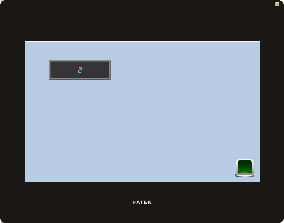
Figure 432 Online simulation illustration
Tip: press ← → to switch chapters, Ctrl+K to search