
This Protocol is each communication port of FATEK PLC to communicate with the peripherals under standard mode. Any peripherals that want to communicate with FATEK PLC model have to meet the rules, not only the hardware connection but also the software parameter setting. Besides, the message format also has to be the same with this protocol so that the PLC can respond normally.
1.1 Master and Slave Definition and Communication
FATEK PLC is defined as slaves in the communication with peripheral devices that are always defined as masters when communicate with FATEK PLC. All the peripheral devices send the message when communicate with FATEK PLC and its respond when receive the message from masters.
Command message
Master Slave (peripheral devices) (FATEK PLC)
Response
1.2 The Communication Message Format of FATEK PLC
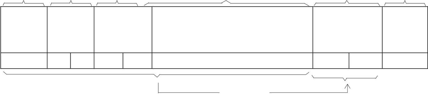
There are 6 data columns in the FATEK PLC communication format including command (master) and response (slave) message.
Sending direction
|
First send |
|
Last send |
|||||||
|
d |
e |
f |
g |
||||||
|
↓ |
↓ |
||||||||
|
c |
h |
||||||||
|
Column name→ |
Start code |
Slave |
Command |
End |
|||||
|
station |
No. |
Data |
Checksum |
code |
|||||
|
No. |
|||||||||
|
ASCII code→ |
STX |
H |
L |
H |
L |
0~500 ASCII code |
H |
L |
ETX |

Pick LRC
cStart code(STX): The hexadecimal code of the STX in ASCII code is 02H. The start characters are all STX in command and response message. The receiving site can determine the data start code with STX.
dThe station No. of slave :The station numbers are hexadecimal two-number value. There is only master station and are 255 slave stations in the PLC communication frame. Every slave station has the only number from 1~FEH.(if the station No. is 0, it means the master can send command to all slaves)When the master want to send command to one or all(station No.=0)it accords the station No. assignment. The slave will send its own station No. when it send response message to master.
Remark: The default value of station No. for PLC is all 1. The station No. can not be amended in the net, it can be changed or amended through FP-08 or WinProladder.
eCommand code :The command No. is two numbers of hexadecimal systems. It is the action which the master wants slave to execute. For example, to read or write the status of discrete, force setting, run, stop… The command No. which is received from master is also included in response message when slave send the response message.
fData information :The data information contains 0(no data)~500 ASCII character. The data in this column is to assign the address or value for reading or writing. The beginning of this data information contains the error code in the response message. In normal condition(no error happened)the error code must be 0(30H)in the beginning and then follow the responding status or value in the response message. When error happened, it will be the error code instead of 0(30H)and it will not follow the data information.
gChecksum :Checksum check the hexadecimal value of ASCII code in the previous c~f columns and produce one checksum value in one byte length (two hexadecimal value 00~FF)with “LRC (Longitudinal Redundancy Check)” method. This message will be checked with the same way at the receiving side when the message is received. When the two check values are the same, it means the data transferred correctly. If the two check values are different, there are some error happened. The calculation of LRC method is to add all the hexadecimal value (8 bits length) of ASCII code and ignore to carry the number to keep the check value at 8 bits length.
hEnd code (ETX):The hexadecimal code of EXT code of ASCII is 03H. The EXT code of either command or response is all ETX. When the receiving side receive the ETX code, it means the data transmission terminated and start to process command or data.
1.3 The Communication Error Code of FATEK PLC
If the error happened in OS command, address, value area of software operation or hardware problem will cause the slave system can not process the command comes from master system. If there is error happened, slave system will respond the message to master system. No matter what command code or data the master system sends, the format of responding message is all the same. Including the required start code (STX), end code (ETX) and checksum value, the command code and station No. will be sent back to master system. The slave system will judge what kind of the error and respond the error code to master system.
● Following table is the response format of communication error of FATEK PLC:
|
Error code |
Description |
|
0 |
Error free |
|
2 |
Illegal value. |
|
4 |
Illegal format, or communication command can not execute. |
|
5 |
Can not run(Ladder Checksum error when run PLC) |
|
6 |
Can not run(PLC ID≠Ladder ID when run PLC) |
|
7 |
Can not run(Snytax check error when run PLC) |
|
9 |
Can not run(Function not supported) |
|
A |
Illegal address |
1.4 The Function Description of Communication Command
In this section only focus on communication command code and explain the command message of master and the response format of slave.(only perform the examples in success)
1.4.1 The Classification and Assignment of Components
The main function of PLC communication is to read and write the status or value inside PLC components. Concerning the discrete and register which are available for read and write and address assignment are as following table:
|
Name |
Discrete address (5 characters) |
16 bits register address(6 characters) |
32 bits register address (7 characters) |
||
|
X |
Input discrete |
X0000~X9999 |
WX0000~WX9984 |
DWX0000~DWX9968 |
|
|
Y |
Output relay |
Y0000~Y9999 |
WY0000~WY9984 |
DWY0000~DWY9968 |
|
|
M |
Internal relay |
M0000~M9999 |
WM0000~WM9984 |
DWM0000~DWM9968 |
|
|
S |
Step relay |
S0000~S9999 |
WS0000~WS9984 |
DWS0000~DWS9968 |
|
|
T |
Timer discrete |
T0000~T9999 |
WT0000~WT9984 |
DWT0000~DWT9968 |
|
|
C |
Counter discrete |
C0000~C9999 |
WC0000~WC9984 |
DWC0000~DWC9968 |
|
|
TMR |
Timer register |
− |
RT0000~RT9999 |
DRT0000~DRT9998 |
|
|
CTR |
Counter register |
− |
RC0000~RC9999 |
DRC0000~DRC9998 |
|
|
HR |
Data register |
− |
R00000~R65535 |
DR00000~DR65534 |
|
|
DR |
Data register |
− |
D00000~D65535 |
DD00000~DD65534 |
|
|
FR |
File register |
− |
F00000~F65535 |
DF00000~DF65534 |
●The discrete status(X,Y,M,S)can combine 16 or 32 continuous status as the 16-bit or 32-bit register, such as the
|
above table WX△△△△ or DWX△△△△ |
, but △△△△ |
should be multiple of 8. |
●It needs 5 characters when assign the discrete address and 6 characters when assign the 16-bit register address and 7 characters to assign the 32-bit register address.
●The address boundary of components in above table is the largest for FATEK PLC. Users should notice the valid address and attribution of each PLC components.(ex. The boundary for X、Y address is 0000~0255; for S is 0000~0999 of FBE-PLC) If exceed the boundary of valid address, PLC will reply error code “A” (illegal address), and will not execute that command.
1.4.2 The Description of Communication Command
●The description of communication command:
|
Command code |
Function description |
Message length can be |
Remark |
|
40 |
The gist read the system status of PLC |
− |
|
|
41 |
Control RUN/STOP of PLC |
− |
|
|
42 |
Single discrete control |
1 point |
|
|
43 |
The status reading of ENABLE/DISABLE of continuous discrete |
1~256 points |
|
|
44 |
The status reading of continuous discrete |
1~256 points |
|
|
45 |
Write the status to continuous discrete |
1~256 points |
|
|
46 |
Read the data from continuous registers |
1~64 Words |
|
|
47 |
Write to continuous registers |
1~64 Words |
|
|
48 |
Mixed read the random discrete status of register data |
1~64 points or Words |
|
|
49 |
Mixed write the random discrete status of register data |
1~32 points or Words |
|
|
4E |
Loop back testing |
0~256 characters |
|
|
53 |
The detail read the system status of PLC |
− |
|
1: The message of discrete status is represented by one character (1 means ON, 0 means OFF) and the data of 16-bit register uses 4 characters to represent the value of one WORD(0000H~FFFFH) 2: The data of 32-bit register is DW(two continuous Words), it has to use 8 characters to represent its data. If the component is 32-bit register, the component has to be treated as 2W. For example, in command code 46 and 47, they can process 64 16-bit components and only process 32 32-bit components. 3: In the command code 48 and 49, the message length is the total of discrete and word. They can not exceed 64W(command 48) and 32W(command 49). As increase one point, its total words will decrease one word. It is the same in the other hand. Because the message length of 32-bit component uses 2 words, it will be less 2 words or point when increase one 32-bit component. For example, the message length of command 48 is 1~64W. If it read 20 32-bit components, its message will occupy 40 words and remain 24W available for discrete or 16-bit register. In this example, command code can read 44 components(20 32-bit components and 24discrete or 16-bit components) in one communication. 4: The operation (read and write) of continuous discrete or register is not only one component and the numbers are continuous so that you don’t need to assign their components number during your assignment. You just only need to appoint the start number and how many components (N). Its operating object can only being one of discrete or register and can not be operated randomly. 5: The random operating objects can read or write several discrete and register. As their number is not continuous, you have to appoint their number and allow operating discrete and register randomly. |
●Command code 40(Read the system status of PLC)
Format
|
MASTER |
S |
0 |
1 |
4 |
0 C 7 |
E |
|
T |
T |
|||||
|
Command |
||||||
|
X |
X |
H L H L H L
|
PLC |
S |
1 |
4 |
0 |
STATUS |
STATUS |
STATUS |
H |
L |
E |
|||
|
T |
T |
||||||||||||
|
response |
1 |
2 |
3 |
X |
|||||||||
|
H |
L |
H |
L |
H |
L |
H |
L |
H |
L |
||||
B0:RUN/STOP
B2:Ladder checksum
error/NORMAL
|
STATUS 1: |
B7 |
H |
B5 |
B4 |
B3 |
B2 |
L |
B1 |
B0 |
B3:USE MEMORY PACK/NOT |
|
USE |
||||||||||
|
B6 |
B4:WDT Timeout/NORMAL |
B5:SET ID/NOT SET ID
STATUS 2: Reserved B6:EMERGENCY
(LADDER STOP/NORMAL program B7:0(RESERVE FOR capacity) FUTURE)
STATUS 3: 0(RESERVE FOR FUTURE)
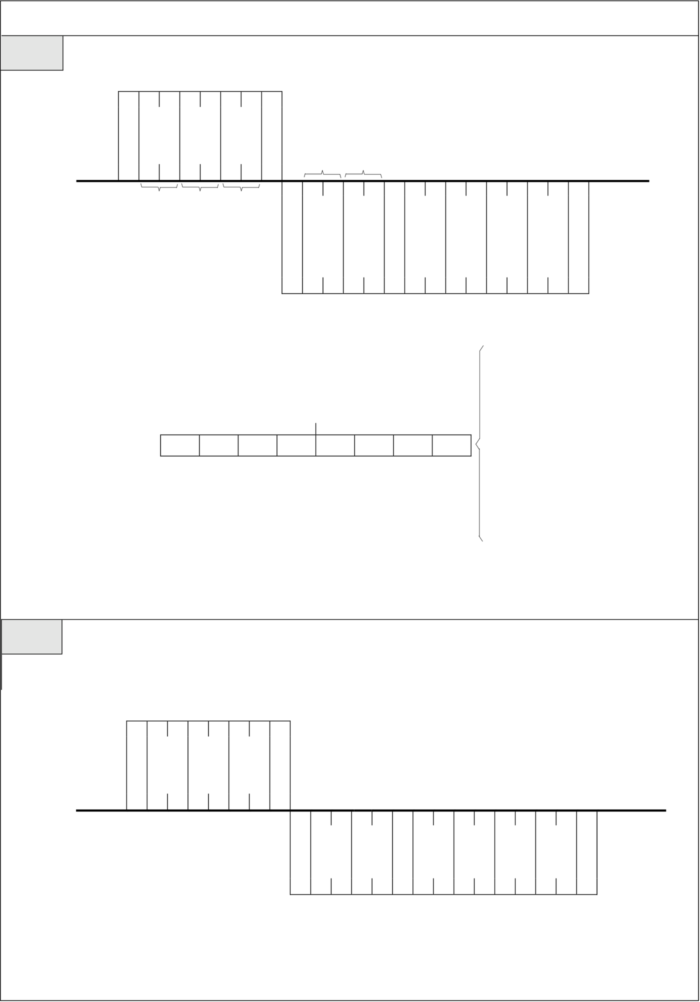
Ex. If the PLC is equipped with MEMORY PACK and ID is set in both PLC and MEMORY PACK and PLC status
is “RUN” under normal condition, the system status of PLC which MASTER read will be as following:
(B5,B3, and B0 are 1 and the other are all 0 that the STATUS is 29H)。
|
MASTER |
S |
0 1 4 0 C 7 |
E |
|
T |
T |
||
|
Command |
|||
|
X |
X |
02H 30H 31H 34H 30H 43H 37H 03H
|
PLC |
S |
E |
|
|
T |
0 1 4 0 0 2 9 0 0 0 0 2 2 |
T |
|
|
X X 02H 30H 31H 34H 30H 30H 32H 39H 30H 30H 30H 30H 32H 32H 03H |
|||
●Command code 41(Control the PLC RUN/STOP)
Format
|
MASTER |
S |
0 |
1 |
4 |
1 |
E |
1 |
H |
L |
E |
||||
|
T |
C 7 |
T |
||||||||||||
|
Command |
||||||||||||||
|
X |
H L H L |
X |
||||||||||||
|
H L |
||||||||||||||
|
S |
||||||||||||||
|
PLC |
T |
1 |
4 |
T |
||||||||||
|
response |
X |
|||||||||||||
|
H |
L |
H |
L |
|||||||||||
|
Control |
0:STOP |
|||||||||||||
|
Ex. |
Turn on PLC to “RUN” |
code |
1:RUN |
|
MASTER |
S |
0 1 4 1 1 F 9 |
E |
|
T |
T |
||
|
Command |
|||
|
X |
X |
02H 30H 31H 34H 31H 31H 46H 39H 03H
|
PLC |
S |
E |
||
|
T |
0 1 4 1 0 F 8 |
T |
||
|
X X 02H 30H 31H 34H 31H 30H 46H 38H 03H |
||||
●Command code 42(Single discrete control)
Format This command can control the appointed discrete to do ENABLE, DISABLE, SET, RESET four activities.
S E
MASTER
T 0 1 4 2 Discrete No. T
Command X X
|
PLC |
H L H L |
H L |
S |
0 1 4 2 |
H L |
E |
|
T |
T |
|||||
|
response |
||||||
|
X |
H L H L |
X |
1:Disable
Running 2:Enable
code 3:Set
4:Reset
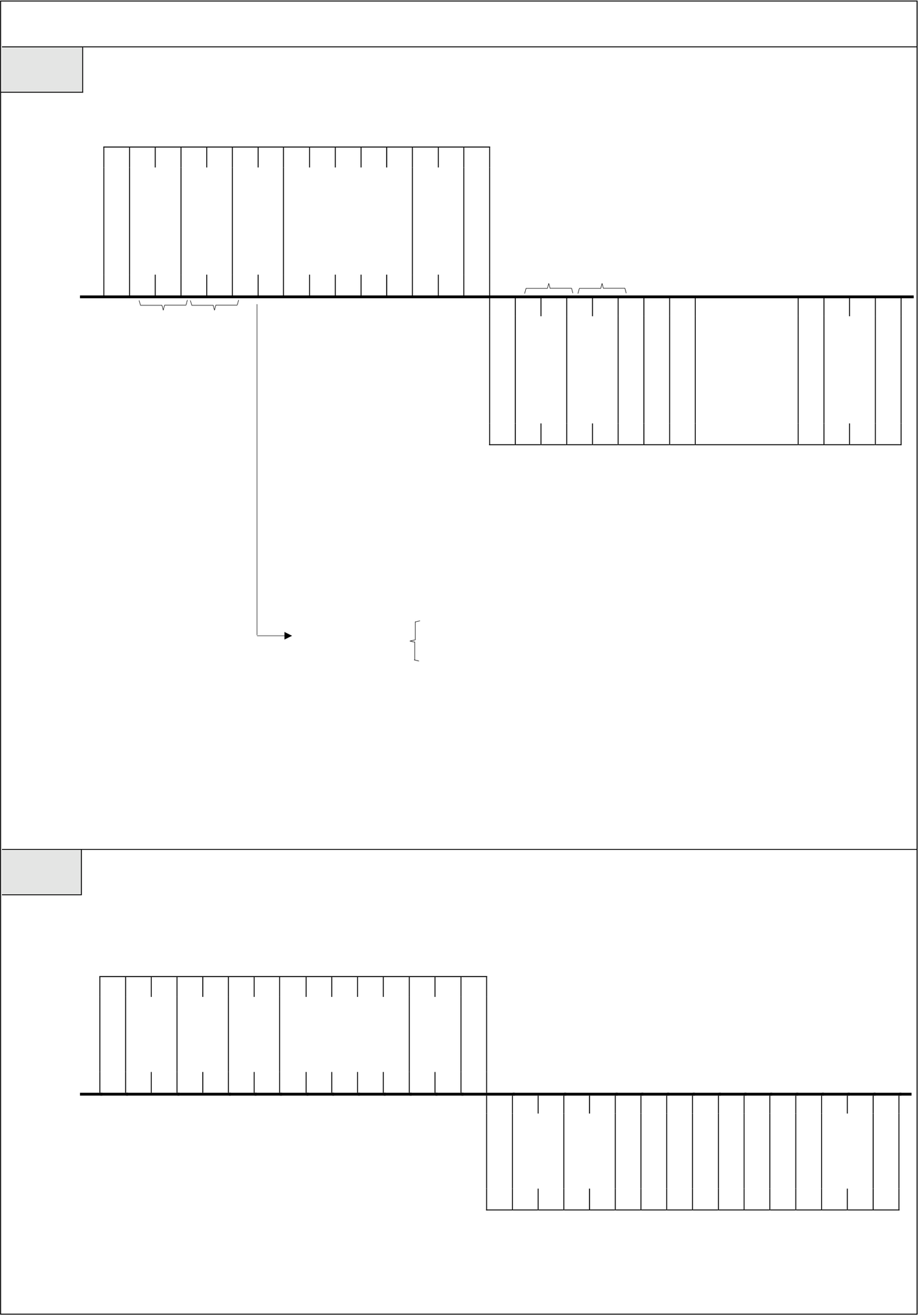
Ex. The following communication format is the example to DISABLE the discrete X16.
|
MASTER |
S |
0 1 4 2 1 X 0 0 1 6 1 9 |
E |
|
T |
T |
||
|
Command |
|||
|
X |
X |
02H 30H 31H34H32H 31H 58H 30H 30H 31H 36H 31H 39H 03H
|
PLC |
S |
0 1 4 2 0 F 9 |
E |
|
T |
T |
||
|
response |
|||
|
X |
X |
02H 30H 31H 34H 32H 30H 46H 39H 03H
●Command code 43(The status reading of ENABLE/DISABLE of continuous discrete)
Format Use this command to read the ENABLE/DISABLE status of continuous adding discrete.
S E
MASTER
T 0 1 4 3 Start No. T
Command X X
|
PLC |
H L H L |
Number N: |
H L |
E |
||
|
S |
||||||
|
T |
0 1 4 3 |
‧‧‧‧ |
T |
|||
|
response |
||||||
|
X |
X |
|||||
|
H L H L |
H L |
|||||
|
The range of Hex value of two number can be |
||||||
|
1≤N≤256(When N=00H it equals to 256) |
||||||
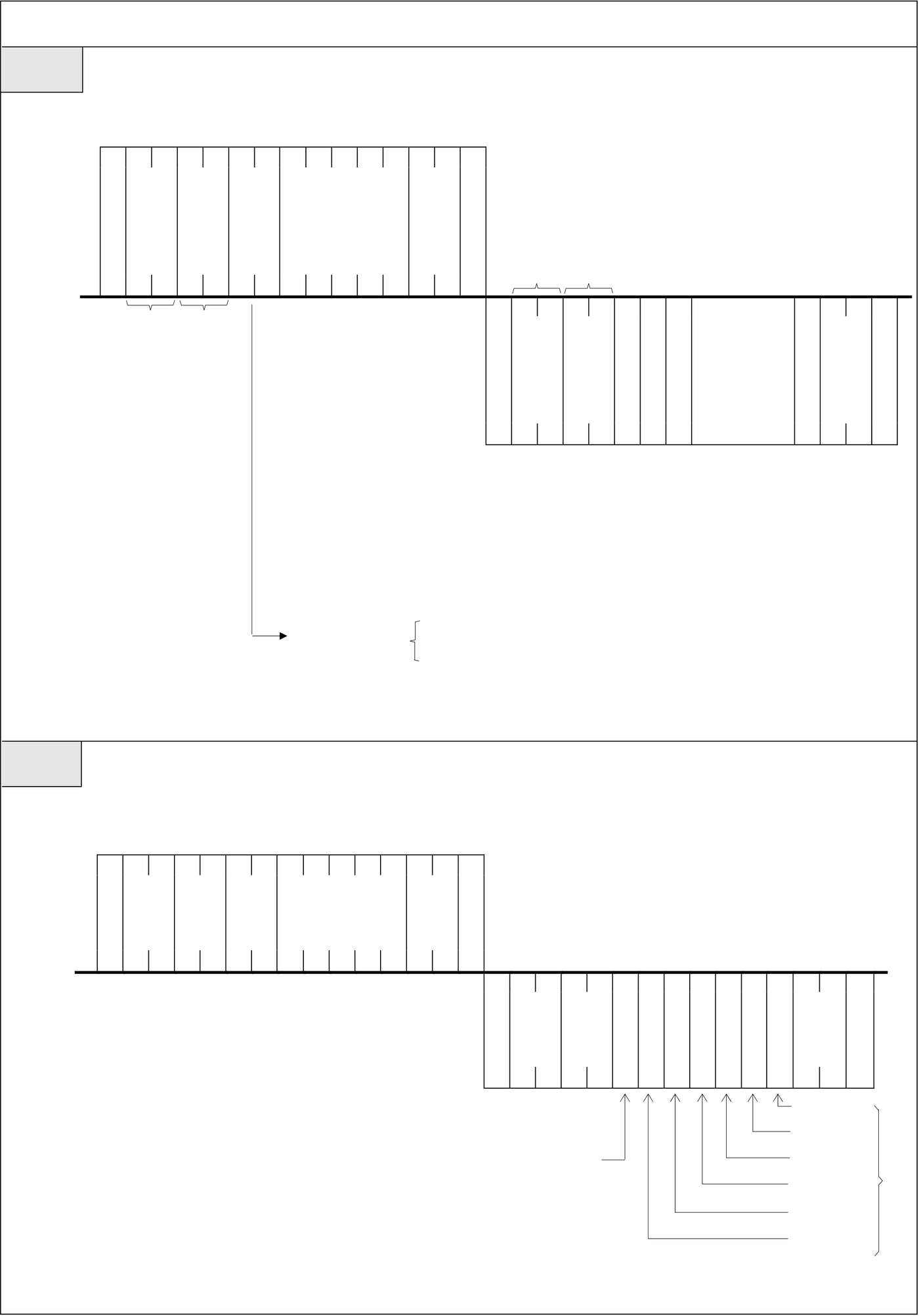
Ex. If Y10,Y12,Y16 of the continuous 7 discrete, Y10~Y16 are DISABLE and the others are all ENABLE, the
PLC status of this command reading is as following.
|
MASTER |
S |
0 1 4 3 0 7 Y 0 0 1 0 4 B |
E |
|
T |
T |
||
|
Command |
|||
|
X |
X |
02H 30H 31H 34H 33H 30H 37H 59H 30H 30H 31H 30H 34H 42H 03H
|
PLC |
S |
0 1 4 3 0 1 0 1 0 0 0 1 4 D |
E |
|
T |
T |
||
|
response |
|||
|
X |
X |
02H 30H 31H 34H 33H 30H 31H 30H 31H 30H 30H 30H 31H 34H 44H 03H
●Command code 44(The status reading of continuous discrete)
Format
|
MASTER |
S |
0 1 4 4 |
Start No. |
E |
|
T |
T |
|||
|
Command |
||||
|
X |
X |
|
PLC |
H L H L |
Number N: |
H L |
E |
||
|
S |
||||||
|
T |
0 1 4 4 |
‧‧‧‧ |
T |
|||
|
response |
||||||
|
X |
X |
|||||
|
H L H L |
H L |
|||||
|
The range of Hex value of two numbers can be |
||||||
|
1≤N≤256(When N=00H, is equals to 256) |
||||||
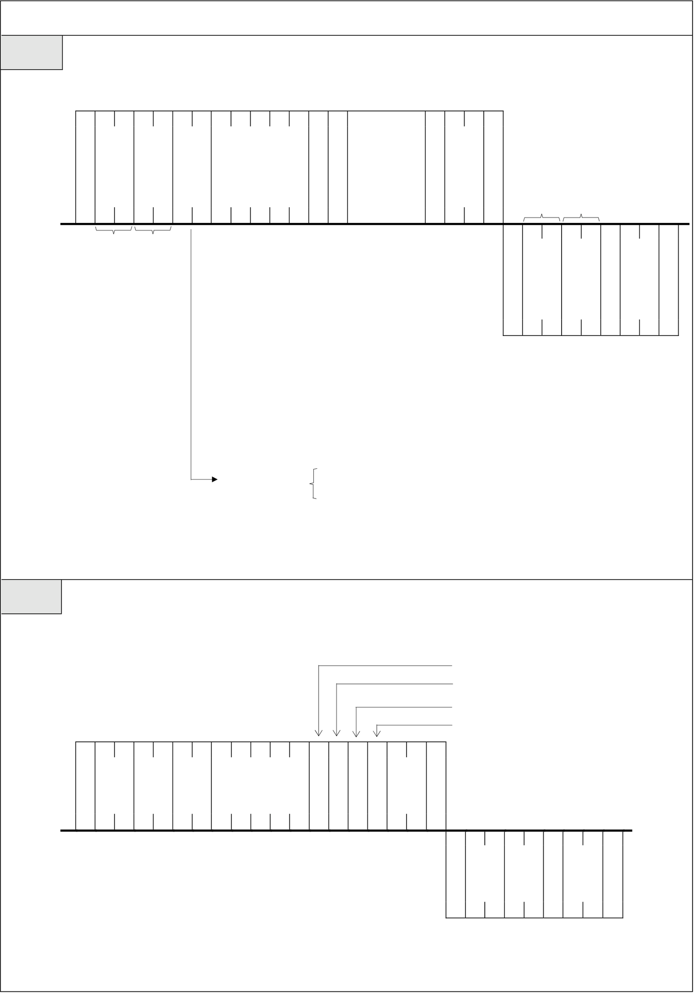
Ex. If the status of X50, X52, X55 are all 0 and X51, X53, X54 are all 1, following is the status of reading the
continuous 6 inputs(X50~X55)
|
MASTER |
S |
0 1 4 4 0 6 X 0 0 5 0 4 E |
E |
|
T |
T |
||
|
Command |
|||
|
X |
X |
02H 30H 31H 34H 34H 30H 36H 58H 30H 30H 35H 30H 34H 44H 03H
|
PLC |
S |
0 1 4 4 0 0 1 0 1 1 0 1 E |
E |
|
T |
T |
||
|
response |
|||
|
X |
X |
02H 30H 31H 34H 34H 30H 30H 31H 30H 31H 31H 30H 31H 44H 03H
X55 Status
X54 Status
|
No error |
X53 Status |
N=6 |
|
X52 Status |
X51 Status
X50 Status
●Command code 45(Write the status to continuous discrete)
Format
|
MASTER |
S |
0 1 4 5 |
Start No. |
‧‧‧‧ |
E |
|
T |
T |
||||
|
Command |
|||||
|
X |
X |
|
PLC |
H L H L |
Number N: |
H L |
E |
||
|
S |
||||||
|
T |
0 1 4 5 |
T |
||||
|
response |
||||||
|
X |
X |
|||||
|
H L H L |
H L |
|||||
|
The range of Hex value of two numbers can be |
||||||
|
1≤N≤256(When N=00H it equals to256) |
||||||
|
Ex. |
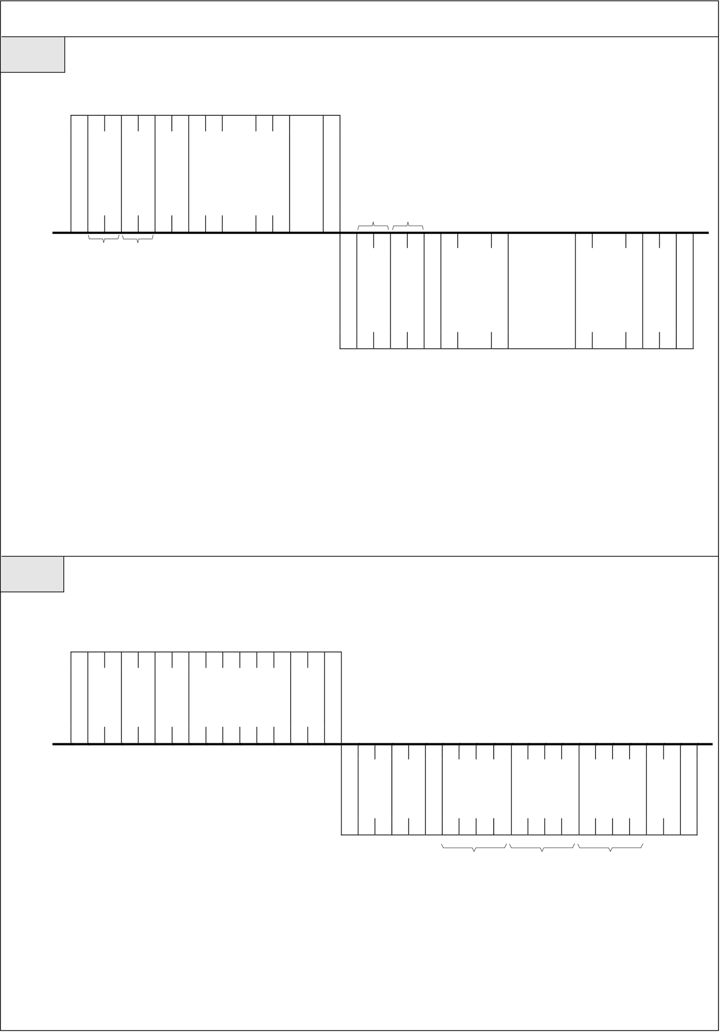
Write the status to continuous 4 outputs(Y0~Y3), Y0 and Y3 are 1, Y1 and Y2 are 0. |
Y0 Status
Y1 Status
Y2 Status
Y3 Status
|
MASTER |
S |
0 1 4 5 0 4 Y 0 0 0 0 1 0 0 1 0 B |
E |
|
T |
T |
||
|
Command |
|||
|
X |
X |
02H 30H 31H 34H 35H 30H 34H 59H 30H 30H 30H 30H 31H 30H 30H 31H 30H 42H 03H
|
PLC |
S |
0 1 4 5 0 F C |
E |
|
T |
T |
||
|
response |
|||
|
X |
X |
02H 30H 31H 34H 35H 30H 46H 43H 03H
●Command code 46(Read the data from continuous registers)
Format
‧‧‧
|
MASTER |
S |
Start register No. |
E |
S |
‧‧‧ |
‧‧‧‧ |
‧‧‧ |
E |
|||
|
T |
0 1 4 6 |
T |
|||||||||
|
Command |
(6 or 7 words) |
||||||||||
|
X |
X |
||||||||||
|
PLC |
H L H L |
‧‧‧ |
H L |
||||||||
|
Data 1 |
Data N |
||||||||||
|
T |
0 1 4 6 |
(4 or 8 |
(4 or 8 |
T |
|||||||
|
response |
|||||||||||
|
X |
number) |
number) |
X |
||||||||
|
H L H L |
‧‧‧ |
‧‧‧ H L |
|||||||||
● Number N consists of Hex value of two numbers, its range can be 01H~40H or 20H(32-bit component)● The number of 16-bit register contains 6 characters and the Hex value of its data contains 4 characters. (It can be shown as 0000H~FFFFH)
● The number of 32-bit register contains 7 characters and the Hex value of its data contains 8 characters.(It can be shown as 00000000H~FFFFFFFFH)
|
Ex. MASTER Command |
Read the data of continuous 3 16-bit registers and start with R12.(R12,R13,R14) |
||
|
S |
E |
||
|
T |
0 1 4 6 0 3 R 0 0 0 1 2 7 5 |
T |
|
|
X |
X |
||
02H 30H 31H 34H 36H 30H 33H 52H 30H 30H 30H 31H 32H 37H 35H 03H
|
PLC |
S |
0 1 4 6 0 1 0 A 5 7 F C 4 0 0 0 1 8 9 |
E |
|
T |
T |
||
|
response |
|||
|
X |
X |
02H 30H 31H34H 36H 30H 31H 30H 41H 35H 37H 46H 43H 34H 30H 30H 30H 31H 38H 39H 03H
|
The data |
The data |
The data |
|
of R12 |
of R13 |
of R14 |
● Refer to the above example, the PLC responds as R12=10A5H, R13=7FC4H, R14=0001H
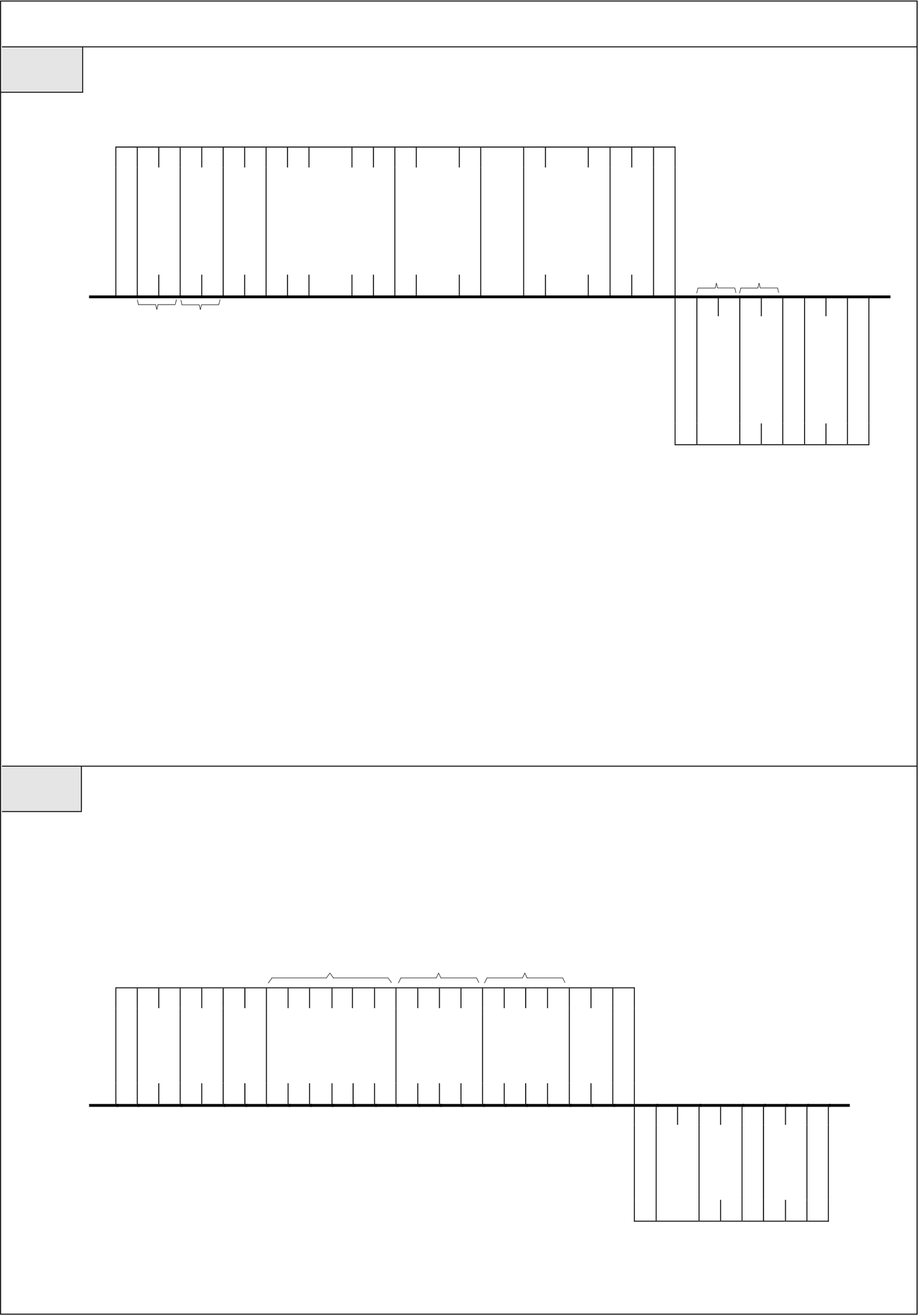
●Command code 47(Write to continuous registers)
Format
|
MASTER |
S |
‧‧‧ |
‧‧‧ |
‧‧‧ |
‧‧‧ |
E |
S |
H L |
E |
||
|
Start register No. |
Data 1 |
Data N |
|||||||||
|
T |
0 1 4 7 |
(4 or 8 |
(4 or 8 |
T |
|||||||
|
Command |
(6 or 7 words) |
||||||||||
|
X |
numbers) |
numbers) |
X |
||||||||
|
PLC |
H L H L |
‧‧‧ |
‧‧‧ |
‧‧‧ H L |
|||||||
|
T |
0 1 4 7 |
T |
|||||||||
|
response |
|||||||||||
|
X |
X |
||||||||||
|
H L H L |
|||||||||||
● Number N consists of Hex value of two numbers, its range can be 01H~40H or 20H(32-bit component)● The number of 16-bit register contains 6 characters and the Hex value of its data contains 4 characters.(It can be shown as 0000H~FFFFH)
● The number of 32-bit register contains 7 characters and the Hex value of its data contains 8 characters.(It can be shown as 00000000H~FFFFFFFFH)
Ex. Input AAAAH to the 16-bit register WY8 and input 5555H to WY24. This is the format of input data to continuous register because WY8 and WY24 are continuous.
|
Start component |
WY8 Data |
WY24 Data |
numbers
|
MASTER |
S |
0 1 4 7 0 2 WY 0 0 0 8 A A A A 5 5 5 5 8 0 |
E |
|
T |
T |
||
|
Command |
|||
|
X |
X |
02H 30H 31H 34H 37H 30H 32H 57H 59H 30H 30H 30H 38H 41H 41H 41H 41H 35H 35H 35H 35H 38H 30H 03H
|
PLC |
S |
0 1 4 7 0 F F |
E |
|
T |
T |
||
|
response |
|||
|
X |
X |
02H 30H 31H 34H 37H 30H 46H 45H 03H
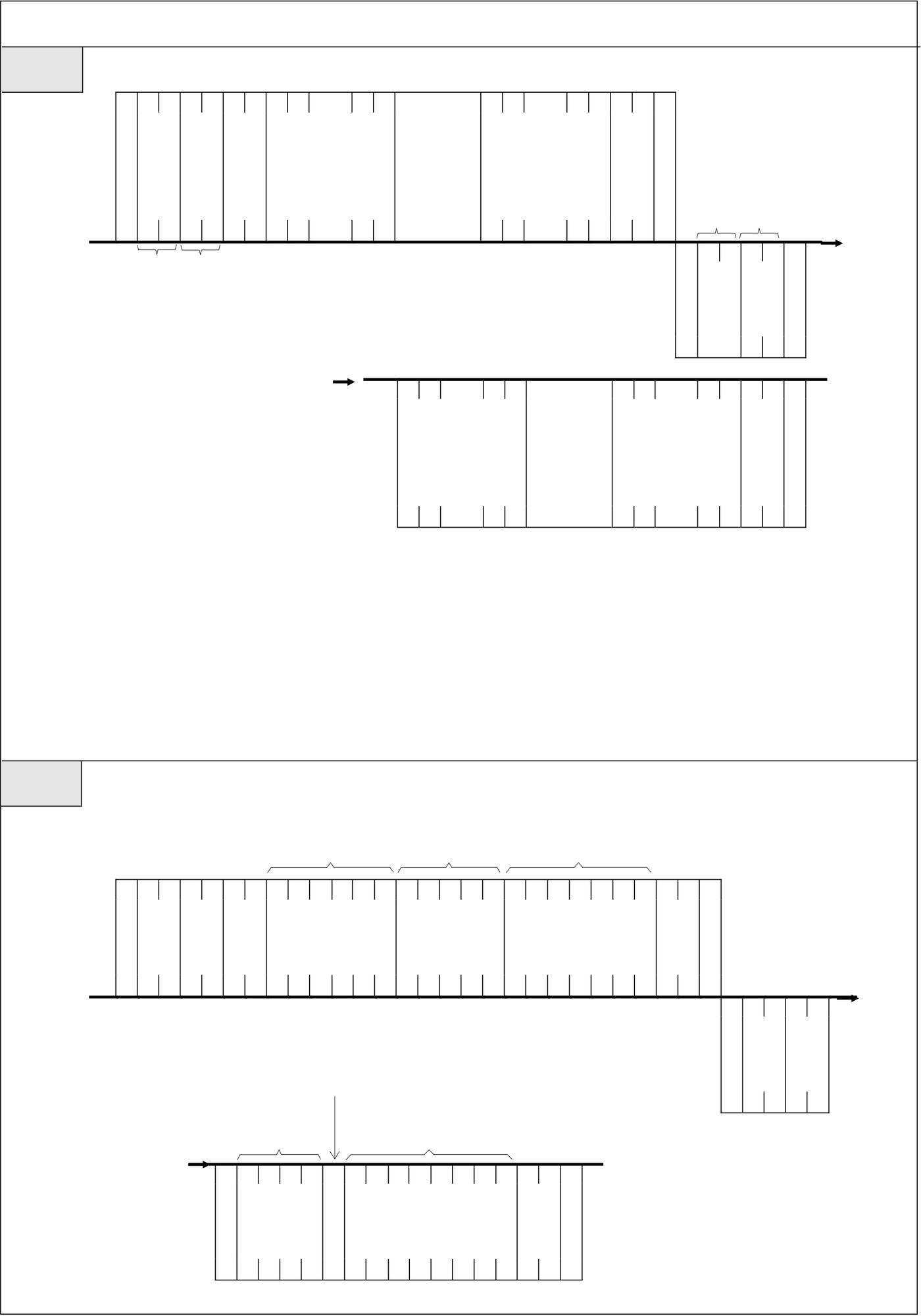
●Command code 48(Mixed read the random discrete status or register data)Format
|
MASTER |
S |
‧‧‧ |
‧‧‧ |
E |
S |
0 1 4 8 |
c |
||
|
(5 , 6 or 7 words) ‧‧‧‧‧‧Component No.N |
|||||||||
|
T |
0 1 4 8 |
T |
|||||||
|
Command |
|||||||||
|
X |
X |
||||||||
|
PLC |
H L H L |
‧‧‧ |
‧‧‧ |
H L |
|||||
|
T |
|||||||||
|
response |
|||||||||
|
X |
|||||||||
H L H L
|
c |
‧‧‧ |
‧‧‧‧‧‧ |
‧‧‧ |
E |
|
|
Component No.1 |
Component No.N |
||||
|
data |
data |
T |
|||
|
(1, 4 or 8 numbers) |
(1, 4 or 8 numbers) |
X |
|||
|
‧‧‧ |
‧‧‧ |
H L |
|||
●Number N consists of Hex value of two numbers, it means the total numbers of components. Its range can be 01H ~40H.(Refer to the item 3)
●If the component is discrete, its number can only be 5 characters and status response can only be one number (1 or 0)
●If the component is 16-bit register, its number can be 6 characters and data response is Hex value of 4 characters. ●If the component is 32-bit register, its number can be 7 characters and data response is Hex value of 8 characters.
|
Ex. |
Read the status and data of R1,Y9 and DWM0(i.e. M31~M0) |
S |
0 1 4 8 |
c |
|||||
|
Component 1 |
Component 2 |
Component 3 |
|||||||
|
MASTER |
S |
0 1 4 8 0 3 R 0 0 0 0 1 Y 0 0 0 9 D W M 0 0 0 0 3 F |
E |
||||||
|
T |
T |
||||||||
|
Command |
|||||||||
|
X |
X |
||||||||
|
02H 30H 31H 34H 38H 30H 33H 52H 30H 30H 30H 30H 31H 59H 30H 30H 30H 39H 44H 57H 4DH 30H 30H 30H 30H 33H 46H 03H |
|||||||||
|
PLC |
The status of |
||||||||
|
T |
|||||||||
|
X |
|||||||||
02H 30H 31H 34H 38H Data of component 1 Data of component 3
c
E
0 5 C 3 4 1 0 0 3 5 4 7 B A C 5 T
X
30H 35H 43H 33H 34H 31H 30H 30H 33H 35H 34H 37H 42H 41H 43H 35H 03H
●In the above example, R1=5C34H and Y9 status is 1(〝ON〞),DWM0=3547BAH
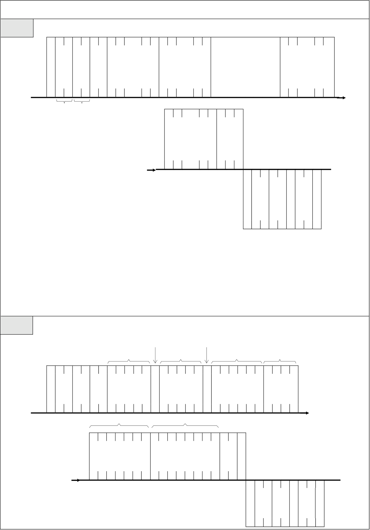
●Command code 49(Mixed write the random discrete status or register data)
Format
|
MASTER |
S |
‧‧‧ |
‧‧‧ |
‧‧‧‧‧‧‧‧‧‧‧ |
‧‧‧ |
c |
|
|
Component No.1 |
Component No.1 |
Component No.N |
|||||
|
T |
0 1 4 9 |
data |
|||||
|
Command |
(5, 6 or 7 words) |
(5, 6 or 7 words) |
|||||
|
X |
(1, 4 or 8 words) |
||||||
|
H L H L |
‧‧‧ |
‧‧‧ |
‧‧‧ |
||||
‧‧‧
|
PLC |
c |
Component No.N |
H L |
E |
S |
H L |
E |
|
|
data |
T |
|||||||
|
(1, 4 or 8 words) |
X |
|||||||
|
‧‧‧ |
||||||||
|
T |
0 1 4 9 |
T |
||||||
|
response |
||||||||
|
X |
X |
|||||||
|
H L H L |
||||||||
● Number N consists of Hex value of two numbers, it means the total numbers of write to components. Its range can be 01H~40H.(Refer to the item 3)
●If the component is discrete, its number can only be 5 characters and status response can only be one number (0 or 1)
● If the component is 16-bit register, its number can be 6 characters and data response is Hex value of 4 characters.
● If the component is 32-bit register, its number can be 7 characters and data response is Hex value of 8 characters.
Ex. Set the status of Y0 at 1, Y1 at 0, 16-bit register WM8 at 5555H, 32-bit register DR2 at FFH.
The status of component 1 The status of component 2
|
MASTER |
Component 1 |
Component 2 Component 3 Data of component 3 |
||
|
S |
||||
|
T |
0 1 4 9 0 4 Y 0 0 0 0 1 Y 0 0 0 1 0 W M 0 0 0 8 5 5 5 5 |
|||
|
X |
||||
|
02H 30H 31H 34H 39H 30H 34H 59H 30H 30H 30H 30H 31H 59H 30H 30H 30H 31H 30H 57H 4DH 30H 30H 30H 38H 35H 35H 35H 35H |
c |
|||
|
Component 4 |
Data of component 4 |
|||
E
D R 0 0 0 0 2 0 0 0 0 0 0 F F 3 C T
X
|
PLC |
c |
44H 52H 30H 30H 30H 30H 32H 30H 30H 30H 30H 30H 30H 46H 46H 33H 43H 03H |
S |
0 1 4 9 0 0 0 |
E |
|
T |
T |
||||
|
response |
|||||
|
X |
X |
02H 30H 31H 34H 39H 30H 30H 30H 03H
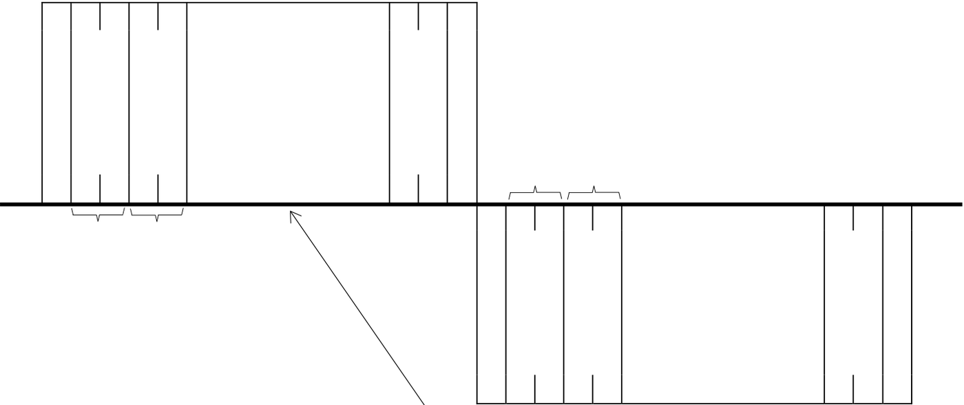
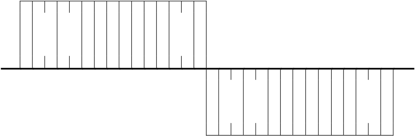
|
●Command code 4E(Loop back testing) |
|||||||||||||||||||||||||||
|
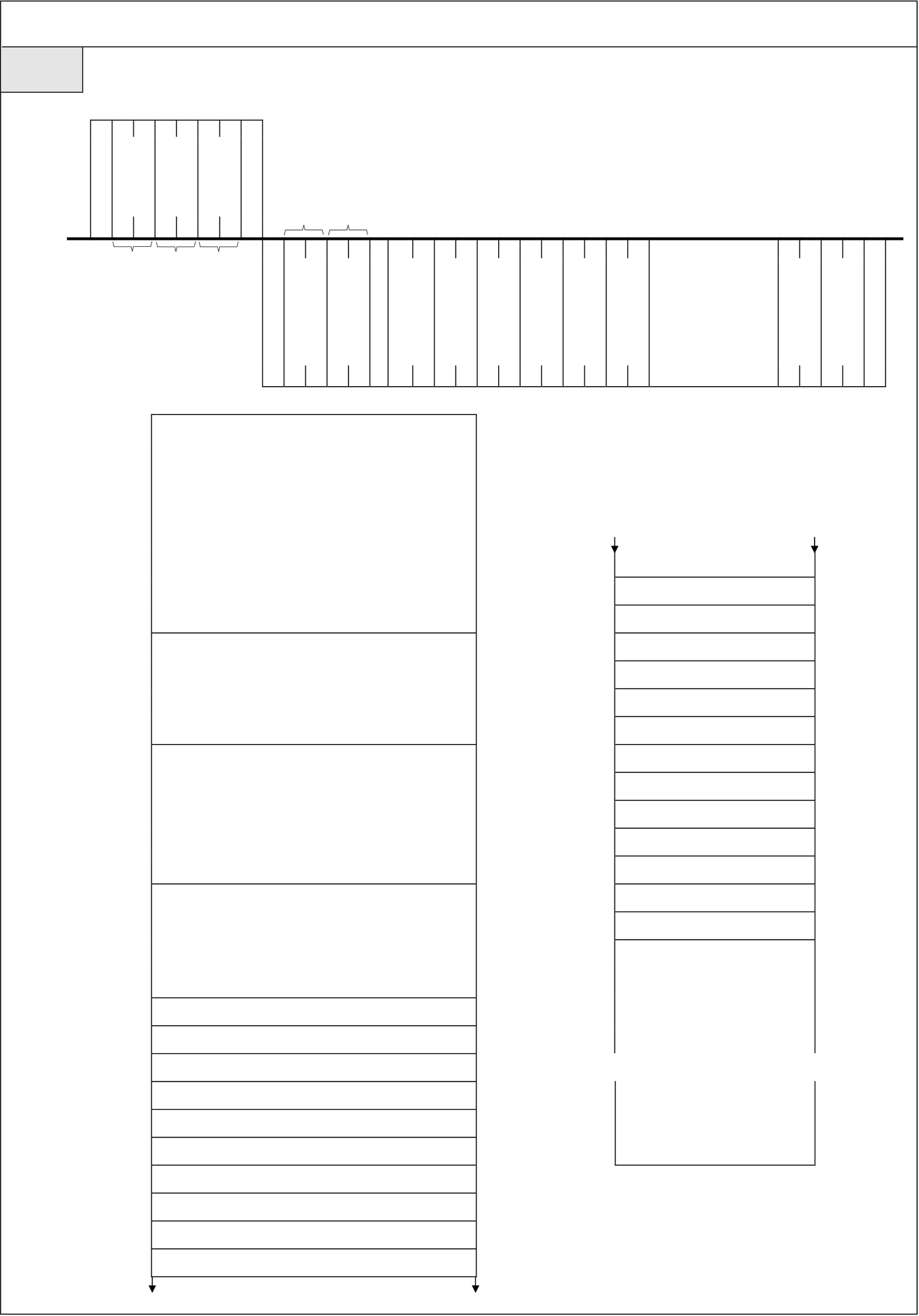
Format This command makes PLC respond all test data back to Master. It is only for testing the communication condition between Master and PLC and it will not influence the PLC function.
These two messages are all the same |
|||||||||||||||||||||||||||
|
Ex. Use this command to send the data〝ABCDEFG〞from Master to PLC to rest weather the PLC respond normally.
02H 30H 31H 34H 45H 41H 42H 43H 44H 45H 46H 47H 42H 38H 03H
02H 30H 31H 34H 45H 41H 42H 43H 44H 45H 46H 47H 42H 38H 03H |
|||||||||||||||||||||||||||
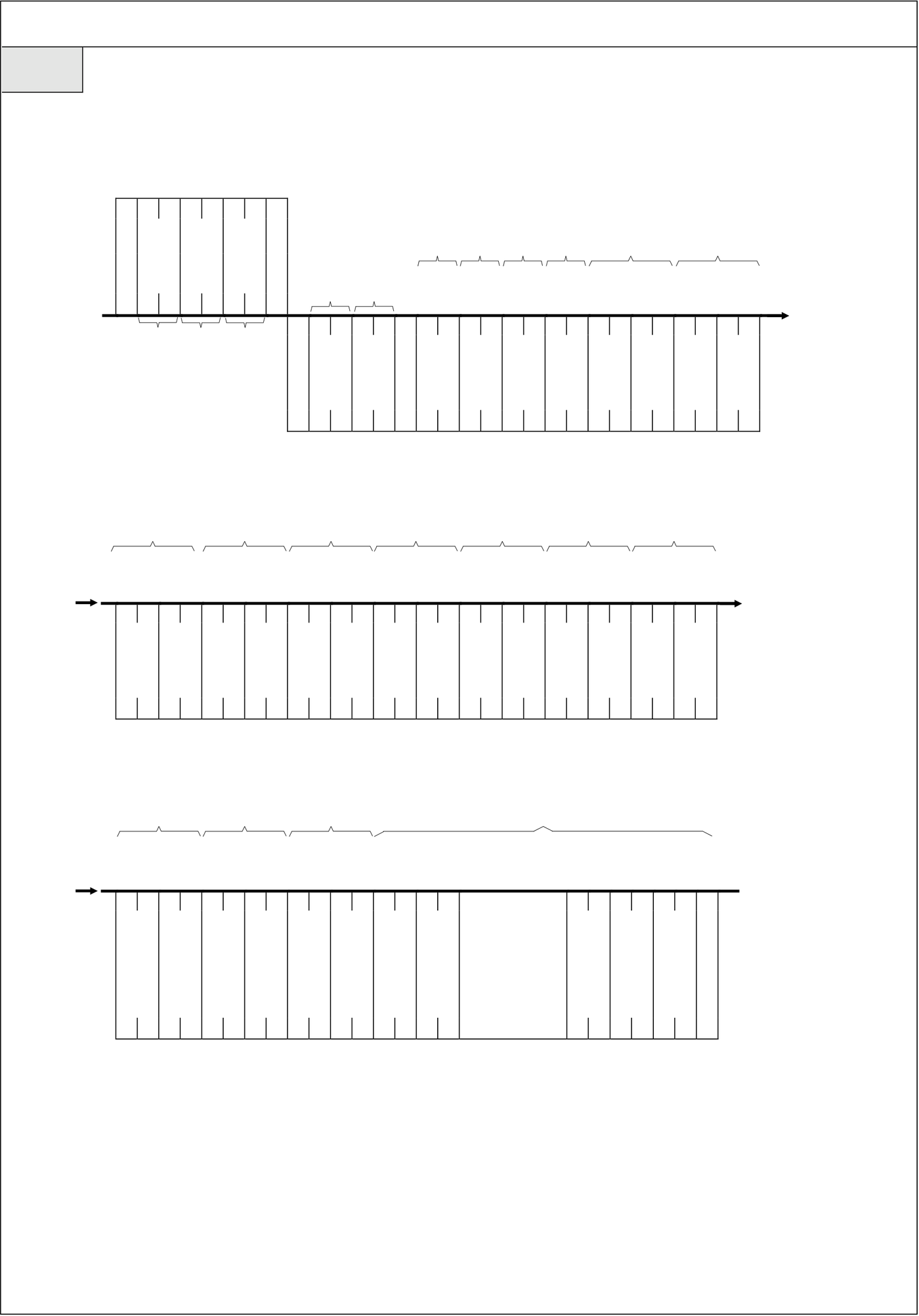
●Command code 53(Read the detailed system status of PLC)
Format
|
MASTER |
S |
0 1 5 3 C B |
E |
|
T |
T |
||
|
Command |
|||
|
X |
X |
H L H L H L
|
PLC |
S |
STATUS |
STATUS |
STATUS |
STATUS |
STATUS |
STATUS |
‧‧‧‧‧‧‧‧ |
STATUS |
E |
|
|
T |
0 1 5 3 |
T |
|||||||||
|
response |
1 |
2 |
3 |
4 |
5 |
6 |
|||||
|
X |
X |
||||||||||
|
H L H L |
H L H L H L H L H L H L |
H L H L |
|||||||||
B0:RUN/STOP
B1:Battery Low/Normal
B2:Ladder checksum error/Normal
|
STATUS 1 |
B3:Use MEMORY PACK/Not use |
STATUS 15 |
M Relay Hi-Byte |
~ |
|
|
B4:WDT Time out/Normal |
|||||
|
B5:ID setting/Not set ID |
|||||
|
STATUS 2 |
B6:Urgent stop/Normal |
STATUS 16 |
M Relay Lo-Byte |
||
|
B7:(reserve for future use) |
STATUS 17 |
S Relay Hi-Byte |
|||
|
Types of Main unit |
STATUS 18 |
S Relay Lo-Byte |
|||
|
00H:MA |
STATUS 19 |
L Relay Hi-Byte |
|||
|
01H:MC |
STATUS 20 |
L Relay Lo-Byte |
|||
|
STATUS 3 |
Other values: retain |
STATUS 21 |
R Register Hi-Byte |
||
|
I/O points of main unit |
STATUS 22 |
R Register Lo-Byte |
|||
|
00H:10 points |
STATUS 23 |
D Register Hi-Byte |
|||
|
01H:14 points |
|||||
|
STATUS 24 |
D Register Lo-Byte |
||||
|
02H:20 points |
|||||
|
STATUS 4 |
˙ |
STATUS 25 |
Timer Hi-byte |
||
|
˙ |
|||||
|
STATUS 26 |
Timer Lo-byte |
||||
|
OS Version of PLC |
|||||
|
STATUS 27 |
Counter Hi-Byte |
||||
|
40H:V4.0X |
STATUS 28 |
Counter Lo-Byte |
|||
|
41H:V4.1X |
STATUS 29 |
||||
|
STATUS 5 |
․ |
․ |
․ |
||
|
․ |
|||||
|
Ladder Size Hi-Byte |
․ |
․ |
|||
|
STATUS 6 |
Ladder Size Lo-Byte |
․ |
․ |
||
|
STATUS 7 |
Discrete input Hi-Byte |
․ |
~ |
․ |
|
|
STATUS 8 |
Discrete input Lo-Byte |
․ |
․ |
||
|
․ |
․ |
||||
|
STATUS 9 |
Discrete output Hi-Byte |
||||
|
STATUS 10 |
Discrete output Lo-Byte |
STATUS 64 |
|||
|
STATUS 11 |
Analog input Hi-Byte |
||||
|
STATUS 12 |
Analog input Lo-Byte |
||||
|
STATUS 13 |
Analog output Hi-Byte |
||||
|
STATUS 14 |
Analog output Lo-Byte |
||||
●Command code 53(Read the detailed system status of PLC)
Ex. If the type of PLC is FBs-20MC, OS version is 4.0x, program capacity is 32K words, without MEMORY PACK, and ID setting, all the status are normal and in RUN model, then the result of reading the system status is as following:
|
MASTER |
S |
0 1 5 3 C B |
E |
S |
MC |
20 |
OS |
Ladder Size |
DI=256 |
c |
||||
|
point |
||||||||||||||
|
V4.0 |
||||||||||||||
|
CPU |
=32KW |
|||||||||||||
|
T |
T |
|||||||||||||
|
Command |
||||||||||||||
|
X |
X |
STATUS |
STATUS |
STATUS |
STATUS |
STATUS |
STATUS |
STATUS |
STATUS |
|||||
|
1 |
2 |
4 |
5 |
6 |
7 |
8 |
||||||||
|
02H 30H 31H 35H 33H 43H 42H 03H |
3 |
|||||||||||||
|
PLC |
0 1 5 3 0 2 1 0 1 0 2 4 0 8 0 0 0 0 1 0 0 |
|||||||||||||
|
T |
||||||||||||||
|
response |
||||||||||||||
|
X |
||||||||||||||
02H 30H 31H 35H 33H 30H 32H 31H 30H 31H 30H 32H 33H 31H 33H 33H 38H 30H 30H 31H 30H 30H
|
c |
DO=256 |
AI=64 |
AO=64 |
MRelay |
S Relay |
L Relay |
R Register |
d |
|||||||
|
= 2002 |
= 1000 |
= 0 |
= 8072 |
||||||||||||
|
STATUS |
STATUS |
STATUS |
STATUS |
STATUS |
STATUS |
STATUS |
STATUS |
STATUS |
STATUS |
STATUS |
STATUS |
STATUS |
STATUS |
||
|
9 |
10 |
11 |
12 |
13 |
14 |
15 |
16 |
17 |
18 |
19 |
20 |
21 |
22 |
||
0 1 0 0 0 0 6 4 0 0 6 4 0 7 D 2 0 3 E 8 0 0 0 0 1 F 8 8
30H 31H 30H 30H 30H 30H 36H 34H 30H 30H 36H 34H 30H 37H 44H 32H 30H 33H 45H 38H 30H 30H 30H 30H 31H 46H 38H 38H
|
D Register |
Timer=256 |
Counter=256 |
STATUS |
STATUS |
reserve |
|||
|
= 4096 |
||||||||
|
STATUS |
STATUS |
STATUS |
STATUS |
STATUS |
STATUS |
|||
|
23 |
24 |
25 |
26 |
27 |
28 |
29 |
30 |
|
d
E 1 0 0 0 0 1 0 0 0 1 0 0 0 0 0 0 ‧‧‧‧ 0 0 0 0 T X
|
30H 43H 30H 30H 30H 31H 30H 30H 30H 31H 30H 30H 30H 30H 30H 30H |
30H 30H 30H 30H |
03H |
Tip: press ← → to switch chapters, Ctrl+K to search