A real time clock (RTC) has been built in the FBs-PLC’s MC/MN main unit. No matter whether the PLC is switched on or off, the RTC will always keep accurate time. It provides 7 kinds of time value data-week, year, month, day, hour, minute and second. Users can take advantage of the real time clock to do 24 hour controls throughout the year (for example, businesses or factories can switch lights on and off at set times each day, control gate access, and do pre-cooling and pre-heating before business or operations begin). It can enable your control system to automatically coordinate with people’s living schedules, and not only will it raise the level of automatic control, it will improve efficiency.
|
15.1 Correspondence Between RTC and the RTCR Within PLC |
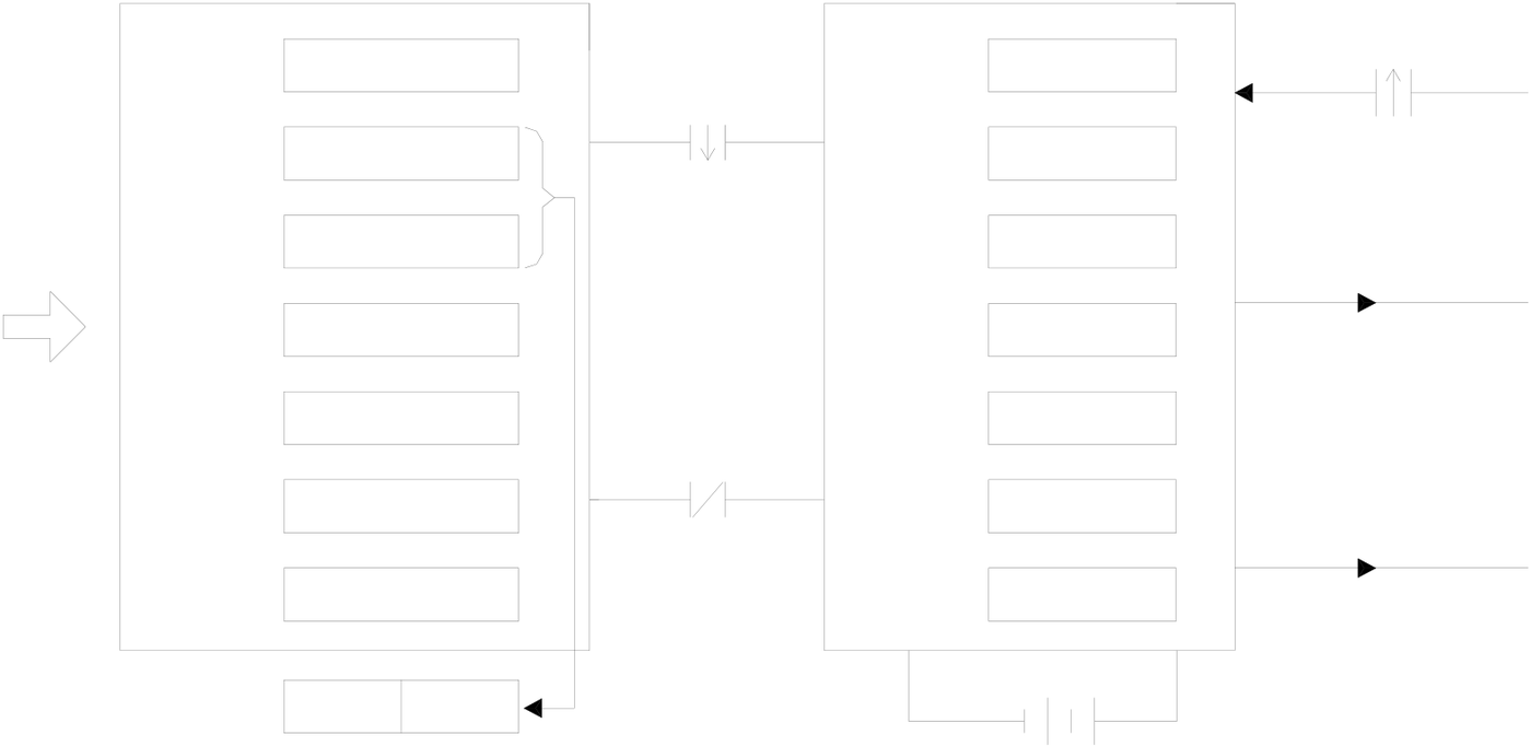
Within PLC, there are special purpose registers (RTCR) for storing the time values of the RTC. There are 8 RTCR registers in all, going from R4128 to R4135. R4128 to R4134 are used to store the 7 kinds of time values mentioned above, from weeks to seconds. Because in practical daily application, certain hour and minute time data is often used, we have specially merged the time values of the hour register (R4130) and minute register (R4129) within RTCR, and put them in R4135 high byte and low byte, so they can be accessed by the user. The diagram below shows the
correspondence between RTC and the RTCR within PLC, as well as the control switch and status flag (M1952-M1955) related to RTC accessing.
|
(R4128~R4134) |
RTC |
(±30 second adjustment) |
|
(IC) |
|
R4128~R4134 |
R4128 |
(Sec)0~59 |
(Set) |
Sec |
0~59 |
M1953 |
|
|
M1952 |
|||||||
|
R4129 |
(Min)0~59 |
(Read Out) |
Min |
0~59 |
(RTC installation detection) |
||
|
R4130 |
(Hrs)0~23 |
Hrs |
0~23 |
||||
|
M1954 |
|||||||
|
( ) |
|||||||
|
R4131 |
(Day)1~31 |
Day |
0~31 |
||||
|
set value write-in |
|||||||
|
(M1952 must be 1) |
|||||||
|
R4132 |
(Mon) 1~12 |
Mon |
0~12 |
||||
|
R4133 |
(Yr)0~99 |
M1952 |
Yr |
0~99 |
(set value error) |
||
|
M1955 |
|||||||
|
R4134 |
(Wk) |
0~6 |
Wk |
0~6 |
( ) |
||
|
R4135 |
Hrs |
Min |
|||||
Standby battery(for use during power failure)
※D4053= 0,no RTC chip installed
= 1,RTC chip is HT1381
= 2,RTC chip is ISL1208
= 3,RTC chip is S35390A

|
15.2 RTC Access Control and Setting |
Within PLC, R4128~R4134 registers have been allocated to store the time values of RTC, and this is of great convenience to the user. However, if you want to load the set values of R1428~R4134 into RTC or read out what is in RTC onto R1428~R4134, and tune the time value etc, then the setting must be done using the special relays (M1952 and M1953) for RTC access. Below is an explanation of the access and adjustment procedures, and the status flag relays.
1. RTC setting:
The (R4128~R4134→RTC) setting action is only executed once at the moment that relay M1952 goes from 1→0 (falling edge).
ON
M1952 Timing stoppedTiming active
At the moment when M1952 goes from 1 to 0, the set
values of R4128 to R4134 within RTCR will be written
into the corresponding hardware registers within RTC.
After M1952 has returned to 0 the timing action will start.
Also, with each scan, CPU will retrieve time values from
RTC in the opposite direction and write them onto
R4128~R4134.
Note: If you want to load the set values into RTC, you must first make M1952 as 1 and then load the set values into R4128~R4134. The loading of the set values into R4128~R4134 can be done via MOVE instruction. However, you must first halt the RTC read out (make M1952 as 1), otherwise the data that you just wrote into R4128~R4134 will immediately be overridden by the time data being read back from RTC in the opposite direction.
2. RTC read out (RTC→R4128~R4135):
whenever the M1952 relay is 0 (RTC timing active). With every scan, CPU will take the time value data within RTC and move it to R4128~R4135. When it is 1, it will not read out. In this case R4128~R4135 can load in the set values and they won’t be overridden.
3. ±30 second adjustment:
At the moment that the status of relay M1953 goes 1, CPU will check the value of the second register (R4128) within RTC. If its value is between 0 and 29 seconds then it will be cleared to 0. If its value is between 30 and 59 seconds then besides being cleared to 0, the minute register (R4129) will be increased by 1 (ie, one minute will be added). This can be used to adjust your RTC time value.
4. M1954 RTC installation detecting flag:
When RTC is fitted to the PLC, relay M1954 will be set as 1; otherwise it will be 0.
5. M1955 set value error flag:
When the time value which is set to RTC’s IC is illegal, then the error flag relay M1955 will be set as 1, and the setting action will not be executed.
Setting calendar with WinProladder
Click the “calendar” Item which in Tool bar :
calendar Æ Click right button and select “New Table” |
||||||||||||||||||||||||||||||||||||||
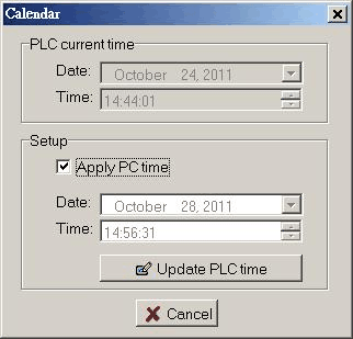
●『 PLC current time 』: It is means current time of PLC in on-line situation. In the “Setup” frame, if “Apply PC time” item is chosen then current time of PC will display below, press “Update PLC time” button to write PC’s current time into PLC. But if “Apply PC time” item isn’t chosen you can modify the Date and Time by yourself. After you change the Date and Time, press “Update PLC time” button to write the Date and time into PLC’s calendar.
|
15.3 RTC Time Calibration |
Real-time Clock is essential in many applications, but due to external temperature changes, the RTC crystal frequency will also change. Thus, the RTC is not as accurate as we expected!
The inaccuracy of Calendar (RTC) circuit in FBs main unit is from crystal frequency. The inaccuracy includes: manufacturing causes, crystal aging and working temperature changes caused by temperature frequency difference (as they are given the technical parameters of crystal products, usually several PPM to tens PPM).
When the crystal frequency is deviated from specific value in actual work, it is caused by time calibration. We must try to compensate the inaccuracy.
As the actual vibration frequency of the same nominal value of each crystal, which matches with a nominal value of capacitor, must fall within in a certain range. In addition, FBs series (D4053=3) provides a digital clock adjustment function. It can also change 32768Hz pulses/second, and then reached adjustment of the clock in which the PLC is to maintain high accuracy travel time. The related time adjustment register is D4054.
According to experimental experiences of time calibration (seconds/day), and then refer to the below table to find the corresponding error and makes correction. It is to improve timing accuracy.
The following table shows the error of seconds when a day goes. The time adjustment register (D4054) is to set the corresponding correction parameters, range is from -16.88 to +16.61 seconds.
Figure 1: Time calibration table when D4053=3
|
Rate |
Time |
Rate |
Time |
Rate |
Time |
Rate |
Time |
|
16.61 |
56FCH |
4.55 |
562DH |
-0.18 |
567FH |
-4.82 |
5693H |
|
16.35 |
567CH |
4.46 |
56CDH |
-0.26 |
56BFH |
-4.91 |
5613H |
|
16.09 |
56BCH |
4.37 |
564DH |
-0.35 |
563FH |
-5.00 |
56E3H |
|
15.83 |
563CH |
4.28 |
568DH |
-0.43 |
56DFH |
-5.09 |
5663H |
|
15.57 |
56DCH |
4.19 |
560DH |
-0.52 |
565FH |
-5.18 |
56A3H |
|
15.31 |
565CH |
4.10 |
56F5H |
-0.60 |
569FH |
-5.27 |
5623H |
|
15.05 |
569CH |
4.01 |
5675H |
-0.69 |
561FH |
-5.36 |
56C3H |
|
14.79 |
561CH |
3.92 |
56B5H |
-0.77 |
56EFH |
-5.45 |
5643H |
|
14.53 |
56ECH |
3.83 |
5635H |
-0.86 |
566FH |
-5.54 |
5683H |
|
14.27 |
566CH |
3.74 |
56D5H |
-0.94 |
56AFH |
-5.62 |
5603H |
|
14.01 |
56ACH |
3.65 |
5655H |
-1.03 |
562FH |
-5.83 |
5656H |
|
13.75 |
562CH |
3.56 |
5695H |
-1.11 |
56CFH |
-6.09 |
5696H |
|
13.49 |
56CCH |
3.47 |
5615H |
-1.20 |
564FH |
-6.36 |
5616H |
|
13.23 |
564CH |
3.38 |
56E5H |
-1.28 |
568FH |
-6.62 |
56E6H |
|
12.97 |
568CH |
3.29 |
5665H |
-1.37 |
560FH |
-6.89 |
5666H |
|
12.71 |
560CH |
3.20 |
56A5H |
-1.45 |
56F7H |
-7.15 |
56A6H |
|
12.45 |
56F4H |
3.11 |
5625H |
-1.54 |
5677H |
-7.42 |
5626H |
|
12.19 |
5674H |
3.02 |
56C5H |
-1.62 |
56B7H |
-7.68 |
56C6H |
|
11.93 |
56B4H |
2.93 |
5645H |
-1.71 |
5637H |
-7.95 |
5646H |
|
11.66 |
5634H |
2.84 |
5685H |
-1.79 |
56D7H |
-8.21 |
5686H |
|
11.39 |
56D4H |
2.75 |
5605H |
-1.88 |
5657H |
-8.48 |
5606H |
|
11.13 |
5654H |
2.66 |
56F9H |
-1.96 |
5697H |
-8.74 |
56FAH |
|
10.86 |
5694H |
2.57 |
5679H |
-2.05 |
5617H |
-9.01 |
567AH |
|
10.60 |
5614H |
2.48 |
56B9H |
-2.13 |
56E7H |
-9.17 |
56BAH |
|
10.33 |
56E4H |
2.39 |
5639H |
-2.22 |
5667H |
-9.43 |
563AH |
|
10.07 |
5664H |
2.31 |
56D9H |
-2.30 |
56A7H |
-9.69 |
56DAH |
|
9.80 |
56A4H |
2.22 |
5659H |
-2.39 |
5627H |
-9.95 |
565AH |
|
9.54 |
5624H |
2.14 |
5699H |
-2.48 |
56C7H |
-10.21 |
569AH |
|
9.27 |
56C4H |
2.05 |
5618H |
-2.57 |
5647H |
-10.47 |
561AH |
|
9.01 |
5644H |
1.97 |
56E9H |
-2.66 |
5687H |
-10.73 |
56EAH |
|
8.74 |
5684H |
1.88 |
5669H |
-2.75 |
5607H |
-10.99 |
566AH |
|
8.48 |
5604H |
1.80 |
56A9H |
-2.84 |
56FBH |
-11.25 |
56AAH |
|
8.21 |
56F8H |
1.71 |
5629H |
-2.93 |
567BH |
-11.51 |
562AH |
|
7.95 |
5678H |
1.63 |
56C8H |
-3.02 |
56BBH |
-11.77 |
56CAH |
|
7.68 |
56B8H |
1.54 |
5649H |
-3.11 |
563BH |
-12.04 |
564AH |
|
7.42 |
5638H |
1.46 |
5689H |
-3.20 |
56DBH |
-12.30 |
568AH |
|
7.15 |
56D8H |
1.37 |
5609H |
-3.29 |
565BH |
-12.57 |
560AH |
|
6.89 |
5658H |
1.29 |
56F1H |
-3.38 |
569BH |
-12.83 |
56F2H |
|
6.62 |
5698H |
1.20 |
5671H |
-3.47 |
561BH |
-13.10 |
5672H |
|
6.36 |
5618H |
1.12 |
56B1H |
-3.56 |
56EBH |
-13.37 |
56B2H |
|
6.09 |
56E8H |
1.03 |
5631H |
-3.65 |
566BH |
-13.64 |
5632H |
|
5.83 |
5668H |
0.95 |
56D1H |
-3.74 |
56ABH |
-13.91 |
56D2H |
|
5.56 |
56A8H |
0.86 |
5651H |
-3.83 |
562BH |
-14.18 |
5652H |
|
5.54 |
56FDH |
0.77 |
5691H |
-3.92 |
56CBH |
-14.45 |
5692H |
|
5.45 |
567DH |
0.69 |
5611H |
-4.01 |
564BH |
-14.72 |
5612H |
|
5.36 |
56BDH |
0.60 |
56E1H |
-4.10 |
568BH |
-14.99 |
56E2H |
|
5.27 |
563DH |
0.52 |
5661H |
-4.19 |
560BH |
-15.26 |
5662H |
|
5.18 |
56DDH |
0.43 |
56A1H |
-4.28 |
56F3H |
-15.53 |
56A2H |
|
5.09 |
565DH |
0.35 |
5621H |
-4.37 |
5673H |
-15.80 |
5622H |
|
5.00 |
569DH |
0.26 |
56C1H |
-4.46 |
56B3H |
-16.07 |
56C2H |
|
4.91 |
561DH |
0.18 |
5641H |
-4.55 |
5633H |
-16.34 |
5642H |
|
4.82 |
56EDH |
0.09 |
5681H |
-4.64 |
56D3H |
-16.61 |
5682H |
|
4.73 |
566DH |
0 |
0000H |
-4.73 |
5653H |
-16.88 |
5602H |
|
4.64 |
56ADH |
-0.09 |
56FFH |
Note: The clock adjustment circuitry only adjusts time calibration. It does not adjust frequency of crystal itself, so there is no change in pulse output 32768Hz.
Examples of setting a range adjustment value
1. When PLC time calibration takes daily faster 3.38 seconds, the time calibration value is 3.38 seconds / day, Look-up the above table to adjust value = 56E5H
2. When PLC time calibration takes daily slower 5.62 seconds, the time calibration is -5.62 seconds / day, Look-up the above table to adjust value = 5603H
Tip: press ← → to switch chapters, Ctrl+K to search