|
16.1 FBs-7SG Overview |
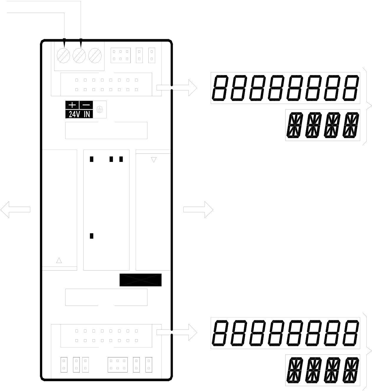
There two models in the FBs-7SG range: 7SG1 and 7SG2. Each of which has one or two 8-digit display driver ICs for driving eight or sixteen 7-segment LED displays using a common ground; or four or eight 16-segment LED displays. The drawing below is an example of FBs-7SG2.
Appearance
External 24V power input
First Channel
CH0
|
Expansion input |
EXT |
O |
O |
Expansion output |
|
(connection to main unit or upper |
POW |
|||
|
(connect to lower level |
||||
|
level expansion unit) |
||||
|
expansion unit) |
||||
FBs-7SG2
CH1
2nd Channel
FBs-7SG has been equipped with an exclusive 7-segment LED display driver IC for multiplexing display of one to eight 7-segment or one to four 16-segment LED displays (one group). With one 16-core flat ribbon cable, users can display 8 digits (numbers) or 64 independent LED displays (8 LEDs for one digit, selectable between digital or LED display) or 4-digit character display. Every 7SG module will occupy three to eight output registers(OR) addresses (R3904~R3967) in the I/O address. Therefore, the PLC can control a maximum of 192 7-segnment displays or 64 16-segment displays or 1024 independent LED displays.
|
16.2 The Procedure of Using FBs-7SG Module |
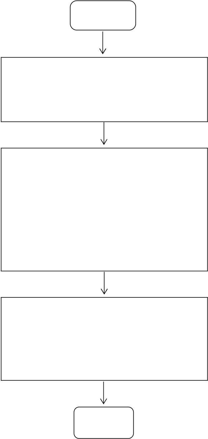
Start
Install FBs-7SG and connect the
24VDC power cable and 7-segnment LED display cable.
z See FBs-7SG Hardware Wiring, Section 16.4.1 for details. Refer to Section 16.4 for details about the circuit of 7-segment LED display
Set appropriate driving voltage for each
group according to the number of LEDs
in each group of the 7-segment display
and adjust LED to the best display condition according to the forward
z See FBs-7SG Hardware Setup, Section 16.4.2 for details.
voltage drop of each group and ensure
no over voltage (OV) has occurred.
Enter OR to the FBs-PLC to light up the
7-segment LED display or display characters and numbers by means of FUN84 (TDSP)
End
|
16.3 FBs-7SG I/O Address |
z See FUN84. TDSP Commands, Section 16.8 for details.
Every FBs-7SG module will occupy three to eight output registers(OR) addresses (R3904~R3967) in the I/O address. In general, WinProladder will detect and calculate the actual I/O addresses occupied by the expansion modules installed on the system after connecting to the PLC. Users may refer to the I/O Module Number Configuration provided by WinProladder in order to find out the exact I/O address of each expansion module to facilitate programming.
|
16.4 FBs-7SG Hardware Wiring and Setup |
|
16.4.1 FBs-7SG Hardware Wiring |
The hardware wiring diagram of FBs-7SG is shown above. In addition to the external 24V power, expansion module input and expansion module output, users will only need to connect the output to a 7-/16-segment LED display board with an 16-core FRC flat ribbon cable.
|
16.4.2 FBs-7SG Hardware Setup |
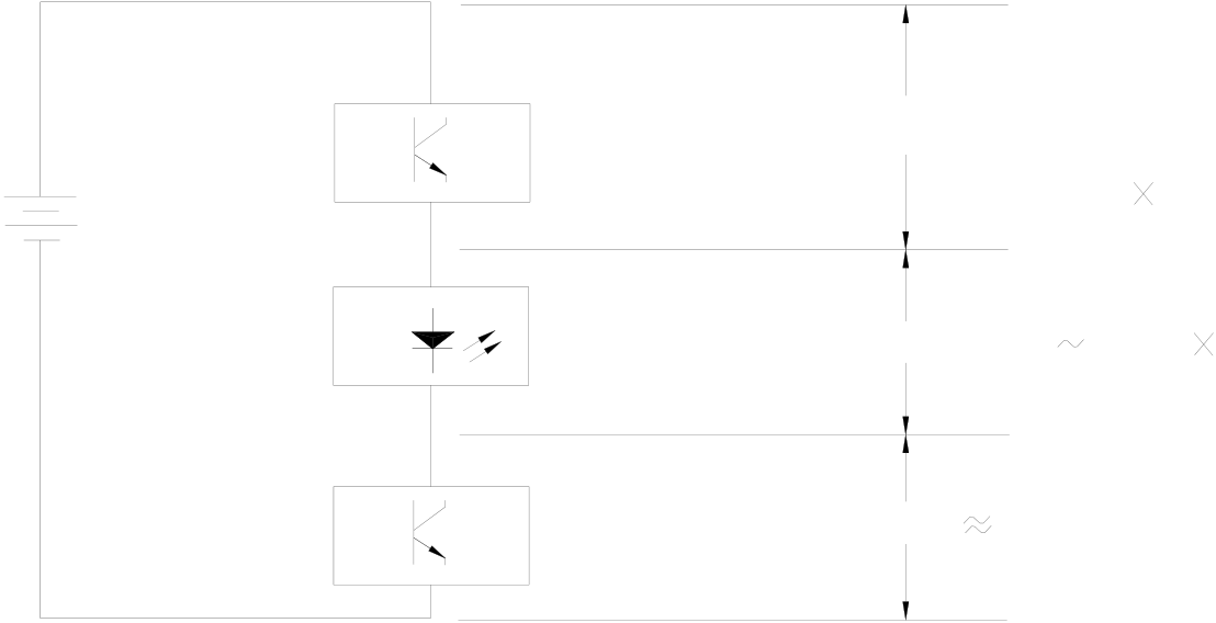
The drawing below presents the output driver circuit of the internal display IC on FBs-7SG. General users will not need to calculate the voltage drop of LEDs. They will only need to adjust the voltage according to the jumper table below in order to prevent over voltage.
40mA
|
Driving power source |
Fixed current for |
VIC=VIN – VLED – 0.8V |
|
displaying IC |
PD=40mAVIC≦ 0.8W |
VIN
|
7-segment LED Multiplexing scan |
VLED=(1.7 |
2.8V) Numbers of cascade |
|
connected amp sect LED VMUX 0.8V(Fixed) |
||
The power consumption will completely depend on the amount of voltage drop VIC (PD = 40mA × VIC) connected to it because the IC current source is fixed at 40mA. As shown in the above diagram, VIC = VIN− VLED− 0.8V, i.e. VIC is affected by the driving current voltage VIN and the forward voltage drop of the 7-segment display VLED, because the safety power consumption of display IC at the severest ambient temperature condition must be controlled at or under 0.8W; i.e. VIC must be smaller than 2V. If the VIC is too low, the brightness of the LED will be reduced; if it is too high, it will result in incorrect display (LEDs that are not supposed to be lighted up will be lighted up) or display IC damage.
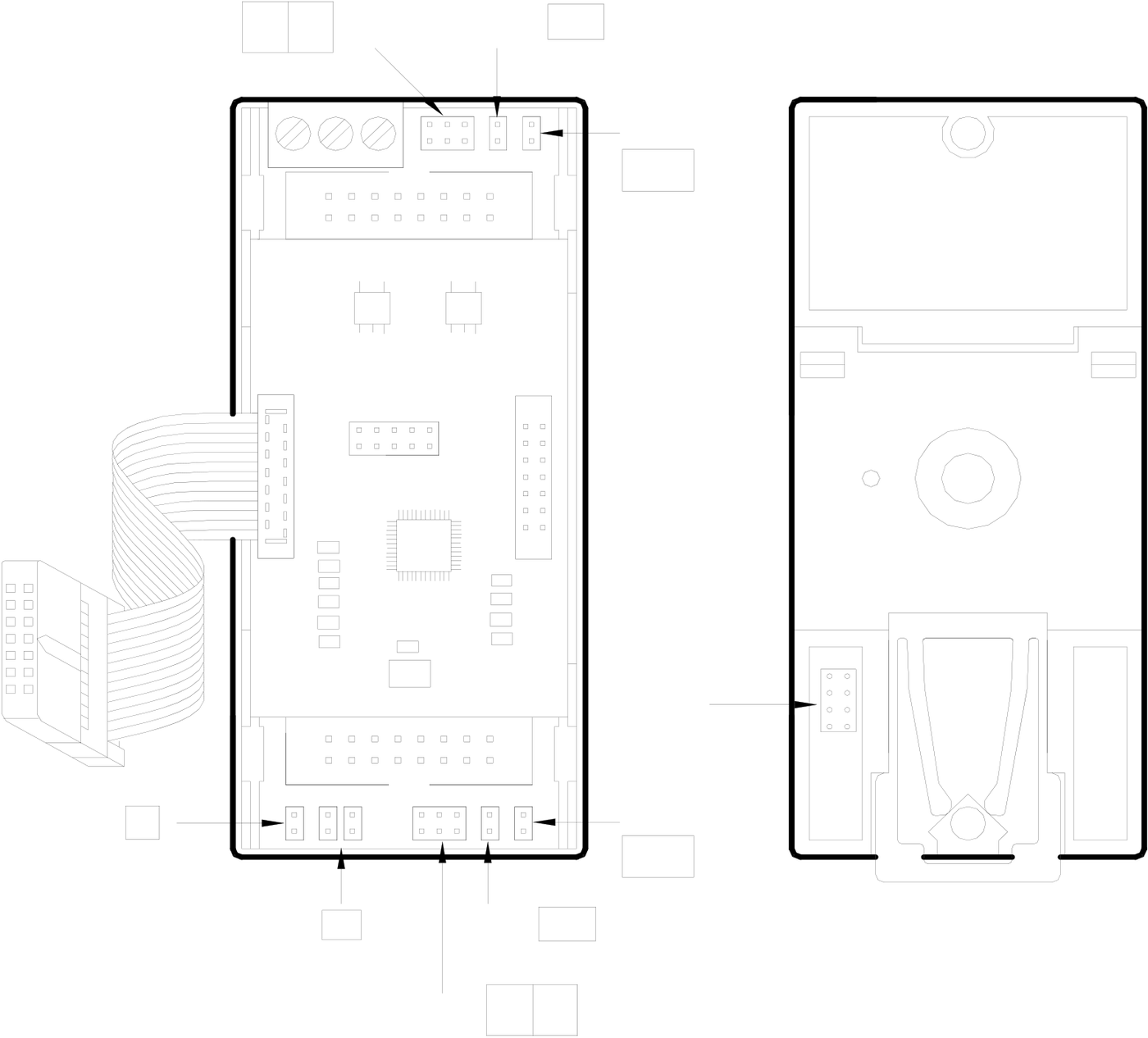
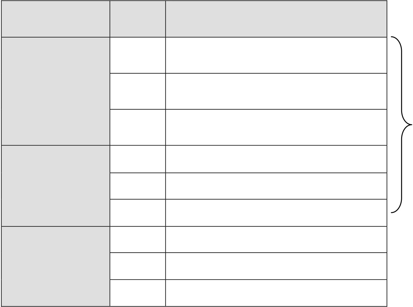
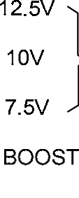
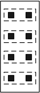
The forward voltage drop of LED is generally between 1.7V and 2.8V. Depending on the size of ordinary 7-segment or 16-segment LED displays, each segment (e.g. a-g) consists of one to five LEDs connected in series. While the range of forward voltage drop among segments will be from 1.7V to 14V, it will be impossible to drive different LED displays with a single voltage. In order to drive the majority 7-segment LED displays, FBs-7SG comes with four driving voltage options at 5V (low-voltage), 7.5V, 10V and 12.5V (high voltage for the last three options) and a fine tuning function at 0.6V-1.8V by means of the diodes and jumpers incorporated to them. In practice, the power supply can drive LEDs of different forward voltages and prevent display IC from blowing by limiting VIC within 2V. The diagrams below show the high/low voltage setup (common) of LED on FBs-7SG, the high/low voltage driving options of displays and the jumper setting of forward voltage drop fine tuning, and its exaction location (as seen after opening the top cover of FBs-7SG).
In this section, we will show you how to obtain the optimal display of 7-/16-segment LED displays without blowing or shorten the life of the display IC by means of driving voltage (VIN) setup, high/low voltage selection and forward voltage fine tuning.
|
FBs-7SG jumper location |
|
HV |
LV |
JP5 |
JP6 .6V |
JP7
1V2
JP1
|
D |
T |
JP9 .6V |
JP10 |
|
JP2 |
1V2 |
JP3
|
JP8 |
HV |
LV |
Jumper Layout (back of module) 插梢位置(背面) |
|
Jumper Layout (open top cover)插梢位置圖(打開上蓋) |
|||
The jumper settings below are referred to FBs-7SG2, because they have covered those in FBs-7SG1.
|
Attribute |
Jumper |
Function |
FBs-7SG1 |
|
FBs-7SG2 |
|
Common |
JP2 |
Decode (D closed)/Non-decode (D |
|||
|
open) setting |
|||||
|
JP3 |
O.V. Test (T) or Normal (No Jumper) |
||||
|
setting |
|||||
|
CH0 |
JP1 |
High Voltage (HV) selection (back of |
|||
|
module) |
|||||
|
JP5 |
|||||
|
High (HV)/Low (LV) voltage selection |
|||||
|
JP6 |
0.6V(0.6V) voltage drop fine tuning |
||||
|
CH1 |
JP7 |
1.2V(1V2) voltage drop fine tuning |
|||
|
JP8 |
High (HV)/Low (LV) voltage selection |
||||
|
JP9 |
0.6V(0.6V) voltage drop fine tuning |
||||
|
JP10 |
1.2V(1V2) voltage drop fine tuning |






|
JP5/JP8 |
JP1 |
JP7/JP10 |
JP6/JP9 |
LED Driving Voltage |
Short JP5/JP8 with a jumper JP1 is located at the back of the module. Turn module over for setup.
Short only one of the three options When BOOST is short, the driving |
||||
|
LV |
Inactive |
Open |
Open |
2.4V |
|||||
|
Open |
Short |
3V |
|||||||
|
Short |
Open |
3.6V |
|||||||
|
Short |
Short |
4.2V |
|||||||
|
HV |
7.5V |
Open |
Open |
4.9V |
|||||
|
Open |
Short |
5.5V |
|||||||
|
Short |
Open |
6.1V |
|||||||
|
Short |
Short |
6.7V |
|||||||
|
10V |
Open |
Open |
7.4V |
||||||
|
Open |
Short |
8V |
|||||||
|
Short |
Open |
8.6V |
|||||||
|
Short |
Short |
9.2V |
|||||||
|
12.5V |
Open |
Open |
9.9V |
||||||
|
Open |
Short |
10.5V |
|||||||
|
Short |
Open |
11.1V |
|||||||
|
Short |
Short |
11.7V |



|
FBs-7SG module default jumper setting |
|
Jumper Number |
Default Jumper Setting |
Note |
|
JP1 |
Locating in third position(7.5V) |
Setting as 7.5V mode |
|
JP2 |
Plugging jumper |
Setting as decode mode |
|
JP3 |
Only plugging in bottom terminal (equal no Setting) |
Don’t do over voltage test(O.V.) |
|
JP5 |
Locating in LV position |
Setting as low voltage mode |
|
JP6 |
Plugging jumper |
Fine tuning 0.6V |
|
JP7 |
No jumper |
|
|
JP8 |
Locating in LV position |
Setting as low voltage mode |
|
JP9 |
Plugging jumper |
Fine tuning 0.6V |
|
JP10 |
No jumper |
|
16.4.3 LED Driving Voltage Setup and Over-Voltage (OV) Inspection |
Users must select the correct driving voltage according to the voltage requirements of LEDs of different sizes before applying the module. If the voltage is too low, the brightness of LEDs will be reduced. If the voltage is too high, the brightness of LEDs will be uneven. More importantly, the LED driver IC will be blown due to over-voltage (O.V.). Therefore, it is necessary to make sure that the CE intermittent voltage (VIC) of the driver IC is below 2V to prevent an O.V. of the driver IC. Yet, it is difficult for users to measure the VIC of driver IC in multiplexing. Therefore, FBs-7SG is equipped with an O.V. LED indicator to facilitate users to check if an OV occurs. The O.V. indicator is located next to the output socket on the panel labeled with O.V.
The result of the O.V. indicator is meaningful only when all segments (a total of 64, including the decimal point) are lighted up. If the O.V. indicator is out in this situation, it means there is no O.V. If the indicator is on, it means there is an O.V. (the indicator may blink or is on constantly if not all segments are lighted up, in this case, it is meaningless). If you want to perform a full segment test, set the TEST Jumper (JP3) to “T” (only when the PLC is OFF) on the lower left part of 7SG or use the convenient command (FUN84:TDSP) on 7SG by setting All Input-ON to “1” (PLC is in “RUN” mode) to light up all segments for an O.V. test.
The following examples show the LED of FBs-7SG module driving voltage setup and O.V. test procedures.
1. Set JP3 to “T”.
2. Start with LV and then adjust driving voltage to the required brightness or the O.V. indicator is on according to the jumper setting as shown in the table above. When the O.V. indicator is on, reduce voltage until the O.V. indicator is off. Please be noted that if the brightness is at its maximum level but it cannot meet the requirements, replace LEDs with higher efficiency.
3. Set JP3 back to ‘N” (normal position) or All Input-ON of FUN84:TDSP to “0”.
|
• Caution |
|
The 7-segment LED display of FBs-7SG is driven by the driver IC with a rated current ≒40mA. The power consumption depends on the VIC of CE because the maximum power limit is only 0.7W/25°C, do not use module in O.V. condition to prevent the driver IC from blowing. |
|
16.5 7-segment LED Display and Individual LED Display Circuits |
|
(D0) g |
(D1) f |
(D2) e |
(D3) d |
(D4) c |
(D5) b |
(D6) a |
(D7) |
7-segment |
displayer or |
Independent LED |
g |
LED |
21 |
non-decoding |
mode |
1(Least significant) |
decoding |
|||
|
cdef |
||||||||||||||||||||
|
3 |
||||||||||||||||||||
|
4 |
||||||||||||||||||||
|
5 |
||||||||||||||||||||
|
b |
6 |
2 |
||||||||||||||||||
|
a |
7 |
|||||||||||||||||||
|
8 |
||||||||||||||||||||
|
g |
||||||||||||||||||||
|
109 |
||||||||||||||||||||
|
cdef |
||||||||||||||||||||
|
11 |
||||||||||||||||||||
|
12 |
||||||||||||||||||||
|
13 |
||||||||||||||||||||
|
b |
14 |
3 |
||||||||||||||||||
|
a |
15 |
|||||||||||||||||||
|
16 |
||||||||||||||||||||
|
4 |
||||||||||||||||||||
|
5 |
||||||||||||||||||||
|
6 |
||||||||||||||||||||
|
15 |
g |
5049 |
7 |
|||||||||||||||||
|
cdef |
||||||||||||||||||||
|
51 |
||||||||||||||||||||
|
52 |
||||||||||||||||||||
|
53 |
||||||||||||||||||||
|
b |
54 |
|||||||||||||||||||
|
8(Most significant) |
||||||||||||||||||||
|
a |
55 |
|||||||||||||||||||
|
56 |
||||||||||||||||||||
|
g |
||||||||||||||||||||
|
5857 |
||||||||||||||||||||
|
cdef |
||||||||||||||||||||
|
59 |
||||||||||||||||||||
|
60 |
||||||||||||||||||||
|
61 |
||||||||||||||||||||
|
b |
62 |
|||||||||||||||||||
|
Digit |
displaying |
of mode |
||||||||||||||||||
|
a |
63 |
|||||||||||||||||||
|
64 |
||||||||||||||||||||
|
Independent |
||||||||||||||||||||
|
displaying |
of |
|||||||||||||||||||
|
1 |
||||||||||||||||||||
16 2
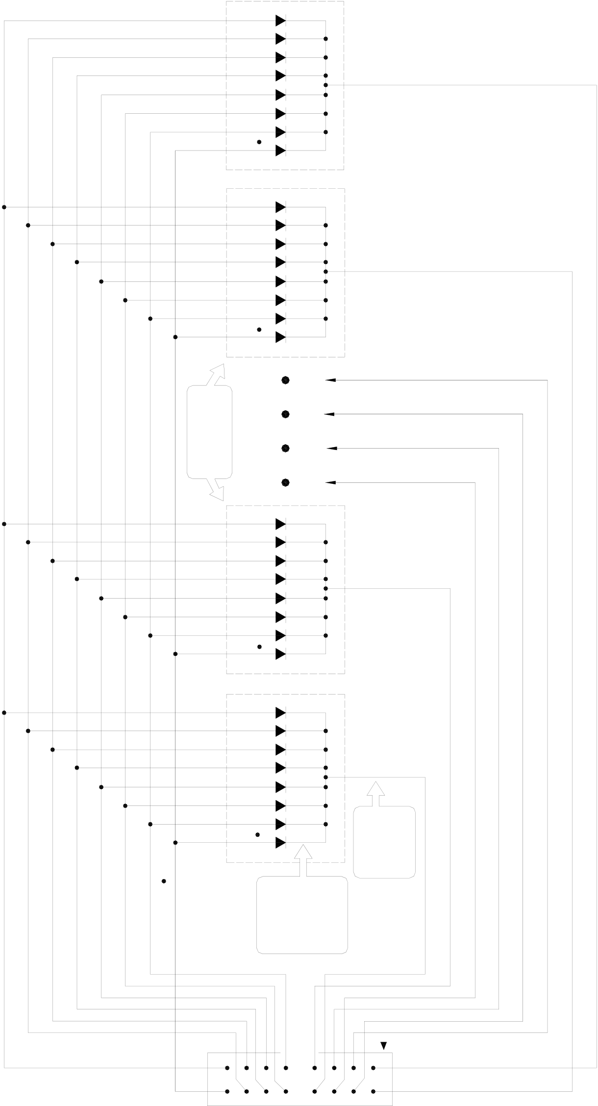
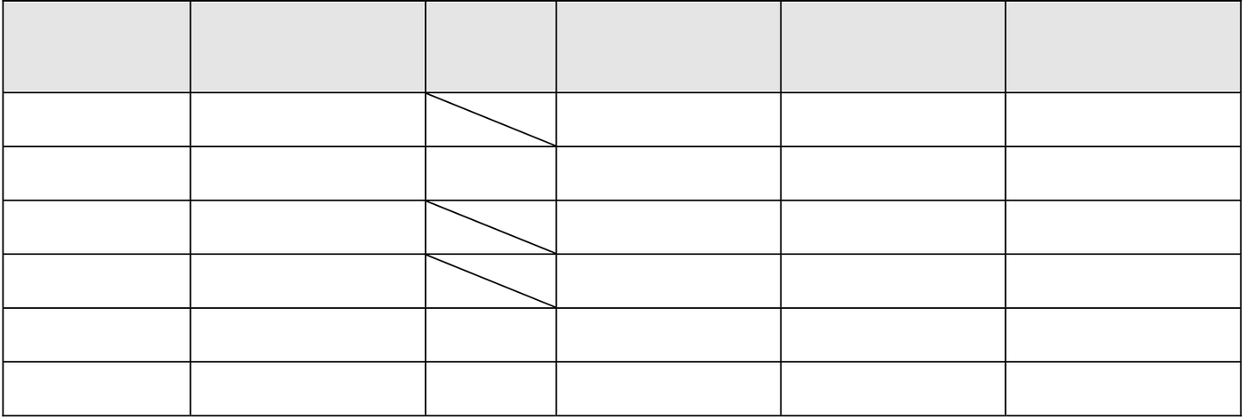
The above diagram indicates the correct wiring (common ground) of the 7-segment LED display or independent LED display of FBs-7SG. Users may make their own display according to this circuit and layout and connect the display to any output socket on FBs-7SG with a 16-pin flat ribbon cable. We offer LED display boards and products in six different dimensions to meet the demands of users. The table below shows the range of our LED display boards and products.
|
Model |
Specification |
|
DBAN.8-nR |
0.8” 4-digit 16-segment LED display, n means R(Red) 16-segment LED characters display installed, can be 1~4 |
|
DBAN2.3-nR |
2.3” 4-digit 16-segment LED display, n means R(Red) 16-segment LED characters display installed, can be 1~4 |
|
DB.56-nR |
0.56” 8-digit 7-segment LED display, n means R(Red) 7-segment LED characters display installed, can be 1~8 |
|
DB.8-nR |
0.8” 8-digit 7-segment LED display , n means R(Red) 7-segment LED characters display installed, can be 1~8 |
|
DB2.3-nR |
2.3” 8-digit 7-segment LED display, n means R(Red) 7-segment LED characters display installed, can be 1~8 |
|
DB4.0-nR |
4.0” 4-digit 7-segment LED display , n means R(Red) 7-segment LED characters display installed, can be 1~4 |
|
※ |
Models inside parentheses are products equipped with LED display and ribbon cable socket. |
|
Recommended pin settings |
|
Model |
HV/LV |
JP1 |
JP7/JP10 |
JP6/JP9 |
Driving Voltage |
|
(JP5/JP8) |
|||||
|
DBAN.8 |
LV |
10V |
Open |
Short |
3V |
|
DBAN2.3 |
HV |
Open |
Open |
7.4V |
|
|
DB.56 |
LV |
10V |
Open |
Open |
2.4V |
|
DB.8 |
LV |
Short |
Open |
3.6V |
|
|
DB2.3 |
HV |
Short |
Short |
9.2V |
|
|
DB4.0 |
HV |
10V |
Short |
Open |
8.6V |
Users can adjust the pin settings tabulated above table on any FATEK standard products. If higher brightness is desired, users can fine-tune the driving voltage according to the jumper settings as shown above. Users must avoid over voltage (O.V.) of output (O.V. indicator will light up) in order not to blow the 7SG module.
Connector pin layout
|
Pin |
Signal |
Pin |
Signal |
|
1 |
DIG0 |
2 |
DIG1 |
|
3 |
DIG2 |
4 |
DIG3 |
|
5 |
DIG4 |
6 |
DIG5 |
|
7 |
DIG6 |
8 |
DIG7 |
|
9 |
a/D0 |
10 |
b/D1 |
|
11 |
c/D2 |
12 |
d/D3 |
|
13 |
e/D4 |
14 |
f/D5 |
|
15 |
g/D6 |
16 |
p/D7 |
There are two display output connectors on 7SG2, each can support 64 segments of LED display. When all segments are on, 8 segments will be scanned at a time for a total of 8 times.
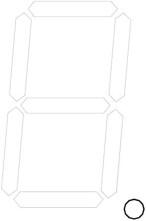
DIG0-DIG7 as tabulated above refer to low active output signals (Sink or NPN output), only one signal will be active (multiplexing) at the same time to select a group of LEDs (8 segments). a/D0-p/D7 are source output signals (PNP) controlling the display of corresponding segments.
|
16.6 Decode Display and Non-Decode Display |
|
○1 Non-decode display: (All segments are dimmed, controlled by user-defined applications independently) |
A total of 8 ORs are equipped on FBs-7SG2 to control the display of 128 segments. Each segment is controlled by a corresponding bit. When the bit value is 1, the corresponding segment will light up. The correlations of each segment and OR is tabulated below. OR is the first output register that occupied by the module. Each OR will output signals twice, i.e. 1 bit of data (8 segments) each time. These data will be transferred to the corresponding outputs p/D7-a/D0.
|
OR |
D15~D8 |
D7~D0 |
|
|
CH0 |
OR+0 |
SEG15~SEG8 |
SEG7~SEG0 |
|
OR+1 |
SEG31~SEG24 |
SEG23~SEG16 |
|
|
OR+2 |
SEG47~SEG40 |
SEG39~SEG32 |
|
|
OR+3 |
SEG63~SEG56 |
SEG63~SEG48 |
|
|
CH1 |
OR+4 |
SEG15~SEG8 |
SEG7~SEG0 |
|
OR+5 |
SEG31~SEG24 |
SEG23~SEG16 |
|
|
OR+6 |
SEG47~SEG40 |
SEG39~SEG32 |
|
|
OR+7 |
SEG63~SEG56 |
SEG63~SEG48 |
|
outputs SEG8-SEG15; the digit on the farthest left of the display board corresponds to outputs SEG63-SEG56. Each 7SG2 can drive sixteen 7-segment LED displays. The digit on the farthest right of the display board (8 digits, max.) corresponds to outputs SEG0-SEG7; the next digit to the left corresponds to |
||||||||||||||||||||
|
16-segment LED correspondence |
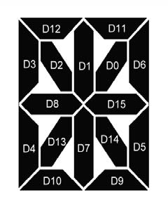
Segments D0-D15 of the digit on the farthest right of the display board (4 digits, max.) correspond to outputs SEG0-SEG15 on 7SG2; the next digit to the left corresponds to outputs SEG16-SEG31; the digit on the farthest left of the display board corresponds to outputs SEG63-SEG48. Each 7SG2 can drive 8 16-segment LED displays.

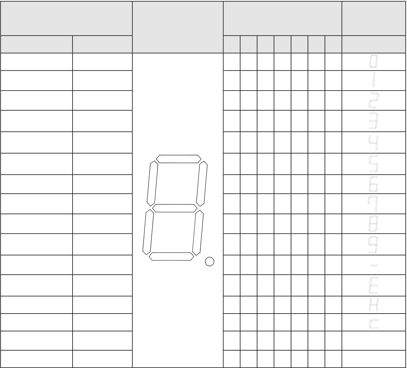
○2Decode Display : Display data on the corresponding segments with default coding
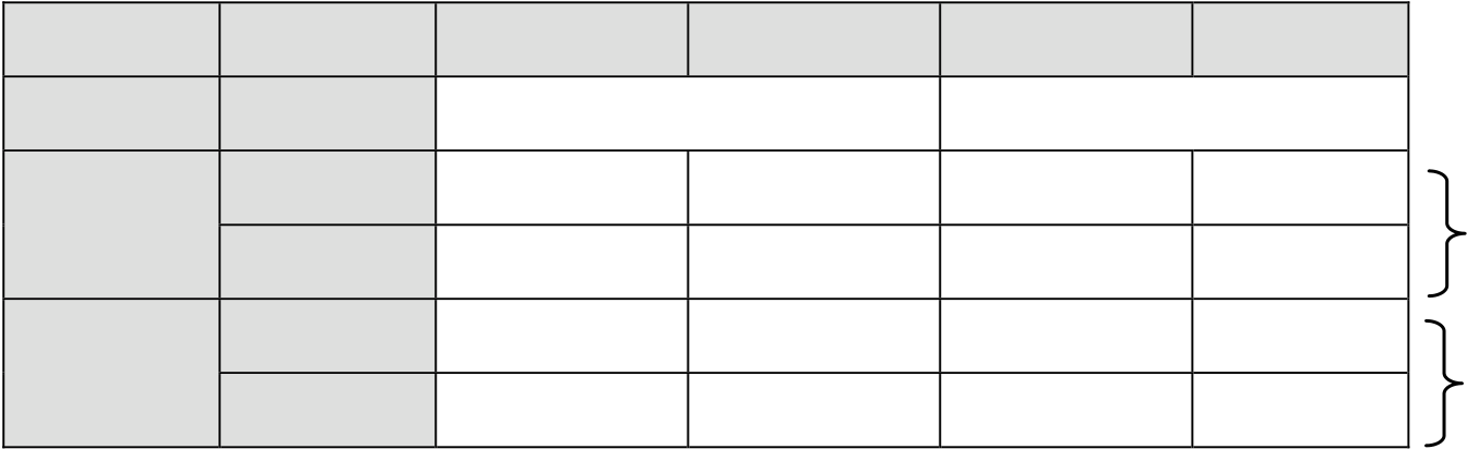
In this mode, a total of 4 output registers(OR) are equipped on FBs-7SG2 to control the display of 8 digits of 7-segment LEDs. Each digit is controlled by 4 bits. The decimal point of an 8-digit number is controlled by the first output register. Each point is controlled by the corresponding bit. The correlations among the digits, decimal point and ORs are tabulated below. OR is the first output register that occupied by the module.
|
Attribute |
OR |
D15~D12 |
D11~D8 |
D7~D4 |
D3~D0 |
1_st 8-digit |
|
Common |
OR+0 |
P15~P8 |
P7~P0 |
|||
|
CH0 |
OR+1 |
DIG3 |
DIG2 |
DIG1 |
DIG0 |
|
|
OR+2 |
DIG7 |
DIG6 |
DIG5 |
DIG4 |
||
|
CH1 |
OR+3 |
DIG3 |
DIG2 |
DIG1 |
DIG0 |
2_nd 8-digit |
|
OR+4 |
DIG7 |
DIG6 |
DIG5 |
DIG4 |
||
OR0 controls the display of decimal point. When the value is “1”, the corresponding decimal point will light up. OR1-OR4 control the display of 16-digit numbers. Each digit will be controlled by four corresponding bits. A total of 16 changes correspond to the following displays.
4-bit digital 7-segment LED decode and non-decode number displays
|
Nibble Value |
7-segment LED |
a |
Segment DIM (0) |
g |
Number |
||||||
|
ON (1) |
|||||||||||
|
Hexadecimal |
Binary |
display structure |
|||||||||
|
b |
c |
d |
e |
f |
|||||||
|
0 |
0000 |
a |
1 |
1 |
1 |
1 |
1 |
1 |
0 |
||
|
1 |
0001 |
0 |
1 |
1 |
0 |
0 |
0 |
0 |
|||
|
2 |
0010 |
1 |
1 |
0 |
1 |
1 |
0 |
1 |
|||
|
3 |
0011 |
1 |
1 |
1 |
1 |
0 |
0 |
1 |
|||
|
4 |
0100 |
0 |
1 |
1 |
0 |
0 |
1 |
1 |
|||
|
5 |
0101 |
1 |
0 |
1 |
1 |
0 |
1 |
1 |
|||
|
6 |
0110 |
f |
b |
1 |
0 |
1 |
1 |
1 |
1 |
1 |
|
|
7 |
0111 |
g |
1 |
1 |
1 |
0 |
0 |
1 |
0 |
||
|
8 |
1000 |
e |
c |
1 |
1 |
1 |
1 |
1 |
1 |
1 |
|
|
9 |
1001 |
d |
P |
1 |
1 |
1 |
1 |
0 |
1 |
1 |
|
|
A |
1010 |
0 |
0 |
0 |
0 |
0 |
0 |
1 |
|||
|
B |
1011 |
1 |
0 |
0 |
1 |
1 |
1 |
1 |
|||
|
C |
1100 |
0 |
1 |
1 |
0 |
1 |
1 |
1 |
|||
|
D |
1101 |
0 |
0 |
0 |
1 |
1 |
0 |
1 |
|||
|
E |
1110 |
0 |
0 |
0 |
1 |
1 |
1 |
1 |
|||
|
F |
1111 |
0 |
0 |
0 |
0 |
0 |
0 |
0 |
|||
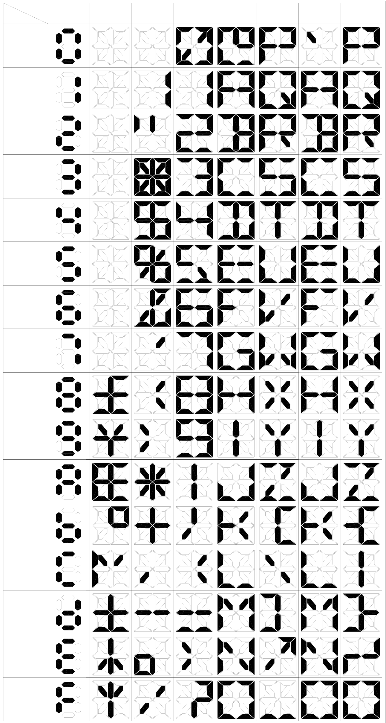
|
ASCII Code and 16-segment number display cross-reference table |
|
M SB |
x000 |
x001 |
x010 |
x011 |
x100 |
x101 |
x110 |
x111 |
|
LSB |
0000
0001
0010
0011
0100
0101
0110
0111
1000
1001
1010
1011
1100
1101
1110
1111
|
16.7 FBs-7SG Input Power Requirements and Consumption |
FBs-7SG is equipped with a DC24V isolated power supply to convert an external 24V power input into power supply for use by the internal circuit and 7-segment LED display on FBs-7SG. The tolerance of input is DC24V±20%.
FBs-7SG consumes 2Wmax when idled. The consumption increases according to the number of 7-segments lighted up. The segment driving current of every display IC on FBs-7SG is 40mA. The driving current for displaying one digit using 8 segments consumes 320mA, and the maximum power consumption of a group is obtained as formulated below:
Pd = 320mA × VIN (LED driving voltage) ÷ 0.8 (power efficiency) W
Total consumption = 2 + Pd × n(W)
For example, the total power consumption of FBs-7SG2 (output from both groups) at maximum power (VIN = 12.5V, all 8 segments are on):
2W +(320mA × 12.5V ÷8 )= 7W
|
16.8 Controlling Display Contents with OR on FBs-7SG |
There are two ways to light up an LED with FBs-7SG. In this section, we will introduce the method of how to light up a 7-segment number display by programming the OR output. In the next section, we will continue with displaying special symbols with FUN84. If displaying numbers with OR controls in decode mode, digits in front of a number will be displayed as 0.
If expansion modules are connected to the FBs PLC, these modules and the I/O address they occupied (see Chapter 12, WinProladder User’s Manual for details) will be displayed on the screen when WinProladder is connected to the PLC. If a FBs-7SG2 is connected to the FBs PLC, users will find in the project window that the system has automatically assigned the output address to FBs-7SG2 when WinProladder is connected to the PLC.
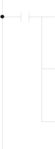
Program example 1 (Decode Display Mode)
Control of 8-digit 7-segment display with FBs-7SG1, with decimal point on. In this case, the FBs-7SG1 must be set to Decode Mode.
|
M0 |
EN |
08.MOV |
|
|
S : |
00FFH |
||
|
D : |
R3904 |
||
08.MOV
|
EN |
S : |
5678H |
|
D : |
R3905 |
08.MOV
|
EN |
S : |
1234H |
|
D : |
R3906 |
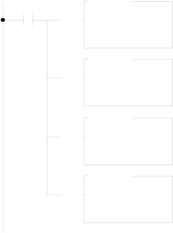
Description :
When M0=1, move the value to be output to the OR. As described above, OR+0 (R3904 in the example) controls the display of decimal point in decode mode; OR+1 (R3905 in the example) controls the display of the lower section of the four digits and OR+2 (R3906 in the example) the upper section of the four digits. The results are:
|
|
7-segment display contents : 1.2.3.4.5.6.7.8. |

Program example 2 (Non-decode Display Mode)
Display numbers on the 8-digit 7-segment display with FBs-7SG1, with decimal point on. In this case, the FBs-7SG1 must be set to Non-decode Mode.
|
M0 |
EN |
08.MOV |
||
|
S : |
EDB0H |
|||
|
D : |
R3904 |
|||
08.MOV
|
EN |
S : |
B3F9H |
|
D : |
R3905 |
08.MOV
|
EN |
S : |
DFDBH |
|
D : |
R3906 |
08.MOV
|
EN |
S : |
CFBDH |
|
D : |
R3907 |
Description :
When M0=1, move the value to be output to the OR. As described above, OR+0 (R3904 in the example) controls the display of the first two digits, OR+1 (R3905 in the example) the third and fourth digits, OR+2 (R3906 in the example) the fifth and sixth digits, and OR+3(R3907 in the example) the last two digits. The results are:
|
|
7-segment display contents :E.d.6.5.4.3.2.1. |

|
16.9FBs-7SG Output Commands FUN84: TDSP |
The TDSP commands are described in the next page.


TDSP
|
FUN84 TDSP |
FBs-7SG Display Module Convenient Commands |
FUN84 TDSP |
||||||||||||||||||||||||||||||||||||||||||||||||||||||||||||||||||||||||||||||||||||||||||||||||||||||||||||||||||||||
S : Starting address of being converted characters
|
||||||||||||||||||||||||||||||||||||||||||||||||||||||||||||||||||||||||||||||||||||||||||||||||||||||||||||||||||||||||
|
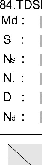
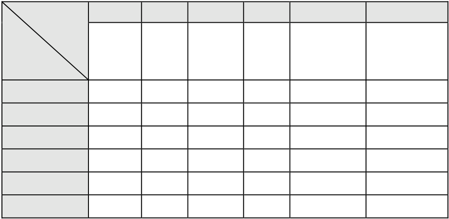
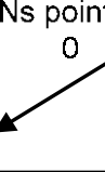
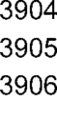
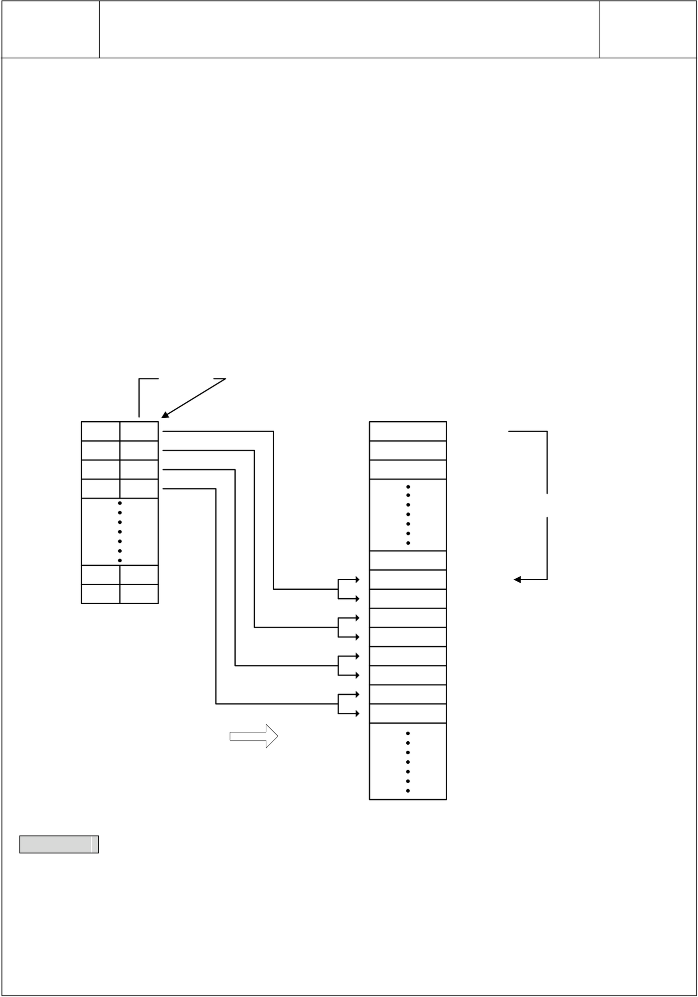
● This convenient instruction is used to generate the corresponding display pattern for FBs series 7-segment or 16-segment display pannel under the control of FBs-7SG1 or FBs-7SG2 modules. When execution control "EN"=1, input "OFF"=0, and input "ON"= 0, this instruction will perform the display pattern conversion, where S is the starting address storing the being converted characters, Ns is the pointer to locate the starting character, Nl tells the length of being converted characters, and D is the starting address to store the converted result, Nd is the pointer to locate the start of storing. There are 4 kinds of operation mode as below: Md=2, Non-decoded display pattern conversion for 7-segment display; the source character is the 4-bit nibble code, the converted result is the 8-bit display pattern. Md=3, Without leading zero display conversion for 7-segment decoded display; the source character is the 4-bit nibble code, the converted result is the 4-bit display pattern without leading zero. Byte 0 or Nibble 0 of S is the 1st displaying character, Byte 1 or Nibble 1 of S is the 2nd displaying character,… Ns operand is the pointer to tell where the displaying character starts Nl operand is the character quantity for conversion |
||||||||||||||||||||||||||||||||||||||||||||||||||||||||||||||||||||||||||||||||||||||||||||||||||||||||||||||||||||||||































TDSP
|
FUN84 |
FBs-7SG Display Module Convenient Commands |
FUN84 |
|
TDSP |
7/16-segment display character and number display conversion |
TDSP |
D operand is the starting address to store the converted display pattern; while Md=0 or 1, one source character of 8-bit ASCII code needs one 16-bit location to store the result; while Md=2, one source character of 4-bit nibble code needs one 8-bit location to store it; while Md=3, one source character of 4-bit nibble code needs one 4-bit location to store it.
Nd operand is the pointer to tell where is the start to store the converted pattern.
● When inputs "OFF"=1, "ON"=0, and "EN"=0/1, the D operand will be filled with the all OFF pattern according to the operation mode, the Nd pointer, and the quantity of Nl.
● When inputs "ON"=1, "OFF"=0/1, and "EN"=0/1, the D operand will be filled with the all ON pattern according to the operation mode, the Nd pointer, and the quantity of Nl.
● Data will be converted differently based on the selected mode. The description below is based on Example 2.
In Example 2, MD=1; S=R0; Ns=0; Nl=8; D=R3904; and Nd=8. Data conversion is presented below.
Example1
8-character of text display by using the FBs-7SG2 display module and 16-Segment display panels; for this application, the FBs-7SG2 module must be set to work at the non-decoded operation mode.
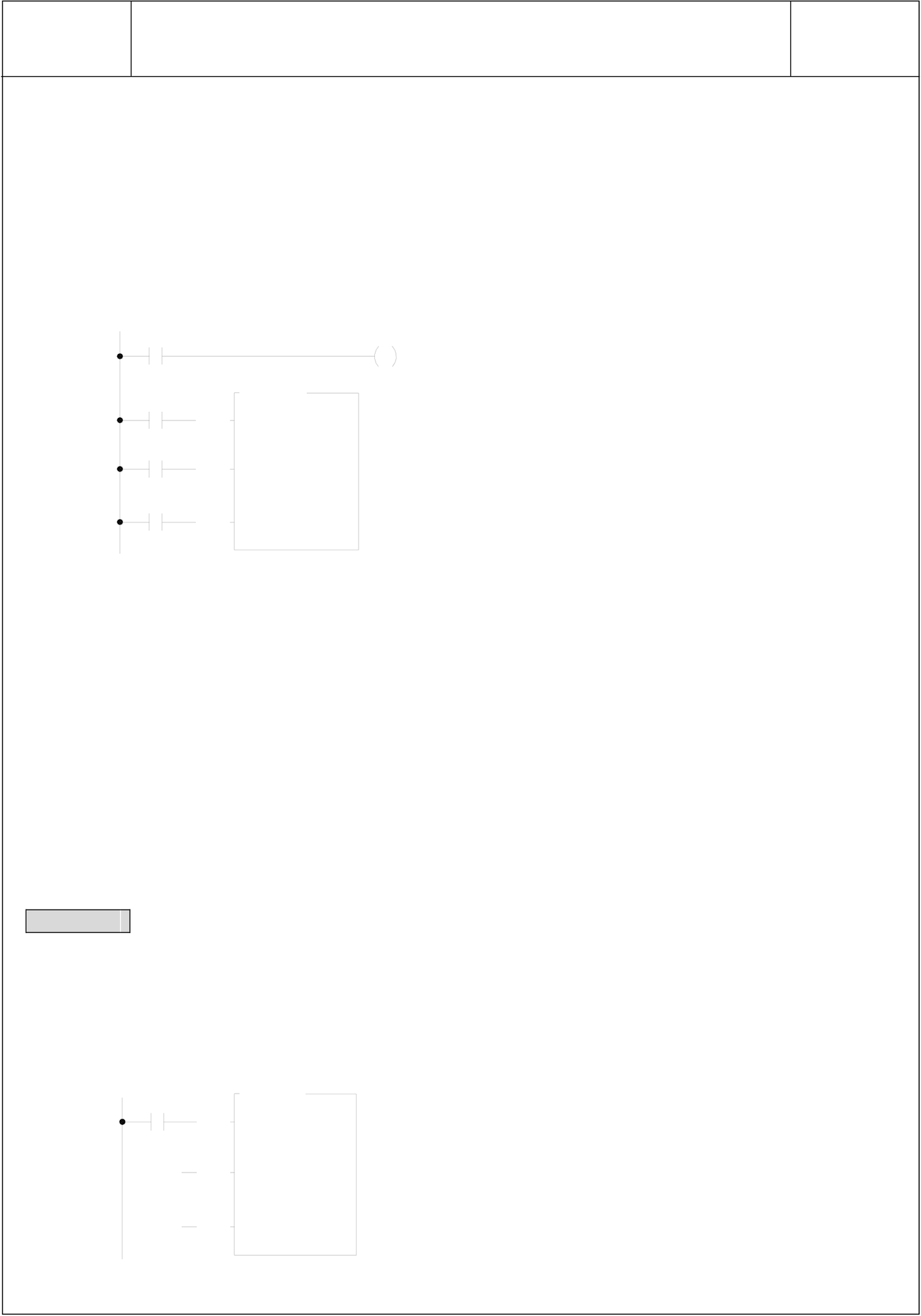
The WinProladder supports the "ASCII Table" editing for easy and convenient text message display; we can create one ASCII Table with the content ‘ WELCOME ‘ for testing, and we assign R5000 is the table starting address, then R5000~R5007 will have the following contents :
TDSP
|
FUN84 |
FBs-7SG Display Module Convenient Commands |
FUN84 |
|
TDSP |
7/16-segment display character and number display conversion |
TDSP |
R5000=2027H (20H= ;27H=’)
R5001=4557H (45H=E;57H=W)
R5002=434CH (43H=C;4CH=L)
R5003=4D4FH (4DH=M;4FH=O)
R5004=2045H (20H= ;45H=E)
R5005=2C27H (2CH=,;27H=’)
R5006=4E45H (4EH=N;45H=E)
R5007=0044H (00H= ;44H=D)
|
S500 |
EN |
84.TDSP |
M1990 |
|||
|
M100 |
||||||
|
MD: |
0 |
|||||
|
M101 |
OFF |
S : |
R5000 |
|||
|
NS: |
2 |
|||||
|
M102 |
Nl : |
8 |
||||
|
ON |
||||||
|
D : |
R3904 |
|||||
|
Nd: |
0 |
|||||
Description: When M100=1, M101=0 and M102=0, the FUN84 will perform the display pattern conversion, where
the source (S) begins from the R5000, the start pointer (Ns) is pointed to byte 2, and the quantity
(Nl) is 8, it means thecontents of R5001~R5004 are the displaying characters; the registers
R3904~R3911 will store the converted pattern for text message displaying (D operand begins from
R3904, Nd operand is pointed to word 0, Nl operand is 8 for quantity)
While M1990=1, the 16-segment panel will display "WELCOME " ;
While M1990=0, the 16-segment panel will display " EMOCLEW".
When M101=1, M102=0, the registers R3904~R3911 will be filled with the all OFF pattern for
displaying.
When M102=1, the registers R3904~R3911 will be filled with the all ON pattern for displaying.
Example2
8-character of display without the leading zero through the second FBs-7SG2 display module and
16-Segment display panels; for this application, the FBs-7SG2 module must be set to work at the non-decoded
operation mode.
|
M110 |
EN |
84.TDSP |
|||
|
MD: |
1 |
||||
|
OFF |
S : |
R0 |
|||
|
NS: |
0 |
||||
|
Nl : |
8 |
||||
|
ON |
|||||
|
D : |
R3904 |
||||
|
Nd: |
8 |
||||
TDSP
|
FUN84 TDSP |
FBs-7SG Display Module Convenient Commands |
FUN84 TDSP |
||
|
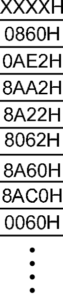
Description When M110=1, the FUN84 will perform the display pattern conversion, where the source (S) begins from the R0, the start pointer (Ns) is pointed to byte 0, and the quantity (Nl) is 8, it means the contents of R0~R3 are the displaying characters; the registers R3912~R3919 will store the converted pattern for message displaying (D operand begins from R3904, Nd operand is pointed to word 8, Nl operand is 8 for quantity). (1) R0=0008H (2) R0=0708H (3) R0=3738H (4) R0=3038H ※The I/O address of FBs-7SG2 in Example 2 must be at R3912~R3919 to ensure the correct display of the message/number (length=8); i.e. other digital or analog output modules may be connected in front of FBs-7SG2.
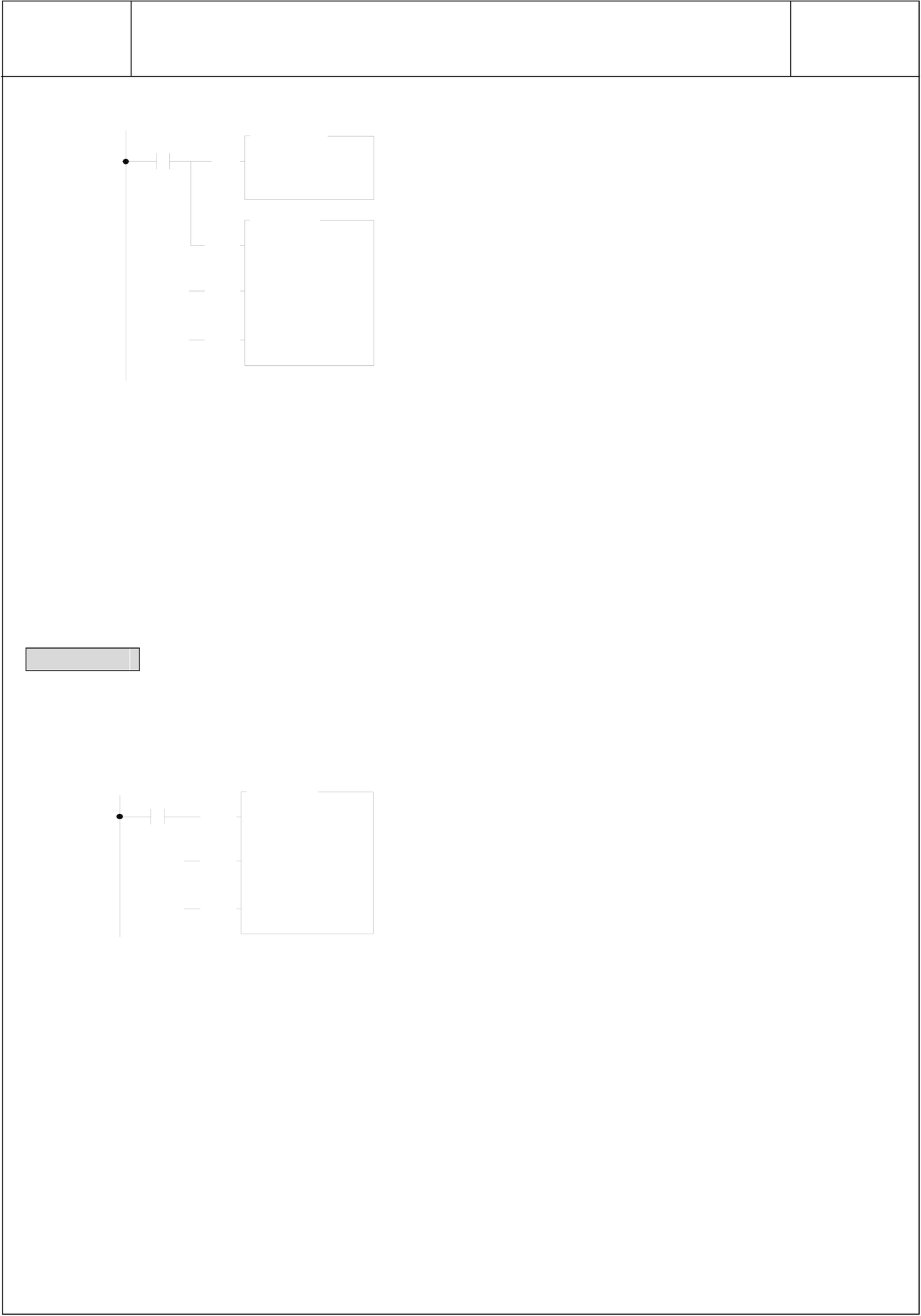
4-digit of numeric display and 32-point of external independent LED’s display through the control of FBs-7SG1 display module and 4-digit of 7-segment display panel; also, it needs the extra circuit to control the 32-point of independent LED’s display. For this application, the FBs-7SG1 module must be set to work at the non-decoded operation mode. |
||||
TDSP
|
FUN84 |
M120 |
FBs-7SG Display Module Convenient Commands |
FUN84 |
|||
|
TDSP |
7/16-segment display character and number display conversion |
TDSP |
||||
|
08D.MOV |
||||||
|
EN |
S : |
W M0 |
||||
|
D : |
R3904 |
|||||
84.TDSP
|
EN |
MD: |
2 |
|
OFF |
S : |
R0 |
|
N S: |
0 |
|
|
Nl : |
4 |
|
|
ON |
||
|
D : |
R3906 |
|
|
Nd: |
0 |
Description : When M120=1, the status of M0~M31 will be copied to the output registers R3904~R3905 to control the display of the 32-point of independent LEDs. The FUN84 also performs the display pattern conversion, where the source (S) begins from the R0, the start pointer (Ns) is pointed to nibble 0, and the quantity (Nl) is 4, it means nibble0~nibble3 of R0 are the displaying characters; the output registers R3906~R3907 will store the converted pattern for displaying (D operand begins from R3906, Nd operand is pointed to byte 0, Nl operand is 4 for quantity).
R0=1024H Æ The 7-segment panel will display "1024"
Example 4
12-digit of decoded numeric display without the leading zero through the control of FBs-7SG2 display module and 12-digit of 7-segment display panels. For this application, the FBs-7SG2 module must be set to work at the decoded operation mode.
|
M 130 |
EN |
84.TD SP |
|
|
M D : |
3 |
||
|
O FF |
S : |
R 0 |
|
|
N S: |
0 |
||
|
O N |
N l : |
12 |
|
|
D : |
R 3905 |
||
|
N d: |
0 |
||
Description:When M130=1, the FUN84 will perform the display pattern conversion, where the source
(S) begins from the R0, the start pointer (Ns) is pointed to nibble 0, and the quantity (Nl) is 12, it means nibble0~nibble11 of R0~R2 are the displaying characters; the output registers R3905~R3907 will store the converted pattern for displaying (D operand begins from R3904, Nd operand is pointed to nibble 0, Nl operand is 12 for quantity).
(1). R2=1234H, R1=5678H, R0=9000H
Display on the 7-segment display : "123456789000"
(2). R2=0000H, R1=5678H, R0=9000H
Display on the 7-segment display : " 56789000"
Tip: press ← → to switch chapters, Ctrl+K to search