18.1FBs-6AD Analog Input Module
FBs-6AD is one of the analog input modules of FATEK FBs series PLC. It provides 6 channels A/D input with 12 or 14 bits effective resolution.. Base on the different jumper settings it can measure the varieties of current or voltage signal. The reading value is represented by a 14-bit value no matter the effective resolution is set to 12 or 14 bits. In order to filter out the field noise imposed on the signal, it also provides the average of sample input function.
18.1.1Specifications of FBs-6AD
|
Item |
Specifications |
Remark |
||
|
Total Channel |
6 Channel |
|||
|
Digital Input Value |
−8192~+8191 or 0~16383(14 bits) −2048~+2047 or 0~4095(12 bits) |
|||
|
Span Of |
Bipolar* |
10V* |
*1.Voltage:−10~10V 5.Current:−20~20mA |
*:It means the default setting |
|
5V |
2. Voltage:−5~5V 6. Current:−10~10mA |
|||
|
Unipolar |
10V |
3. Voltage:0~10V 7. Current:0~20mA |
||
|
5V |
4. Voltage:0~5V 8. Current:0~10mA |
|||
|
Resolution |
14 or 12 bits |
|||
|
Finest resolution |
Voltage:0.3mV |
= Analog input signal / 16383 |
||
|
I/O Points Occupied |
6 IR(Input Register) |
|||
|
Accuracy |
Within ±1% of full scale |
|||
|
Conversion Time |
Updated each scan |
|||
|
Maximum absolute input signal |
Voltage:±15V(max) |
It may cause the destruction to hardware if exceeds this value. |
||
|
Input resistance |
63.2KΩ(Voltage input)、250Ω(Current input) |
|||
|
Isolation |
Transformer(Power) and photocouple(Signal) |
|||
|
Indicator(s) |
5VPWR LED |
|||
|
Supply Power |
24V-15%/+20%、2VA |
|||
|
Internal Power Consumption |
5V、100mA |
|||
|
Operating Temperature |
0 ~ 60 ℃ |
|||
|
Storage Temperature |
-20 ~ 80 ℃ |
|||
|
Dimensions |
40(W)x90(H)x80(D) mm |
|||
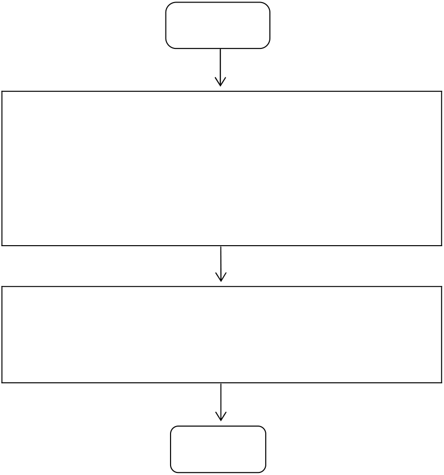
18.1.2The Procedure of Using FBs-6AD Module
Start
Set the I/O voltage/current (V/I), polarity (B/U), and
|
the V/I range of each point before installation. |
——- |
Please refer to section 18.1.4 for hardware |
|
Connect FBs-6AD to the expansion interface on |
||
|
explanation. |
||
|
PLC in series and connect an external 24VDC |
source and analog output wires to the module.
Directly read the value of the six corresponding
value input registers to obtain the analog input
reading of CH0~CH63.
End
|
18.1.3Address Allocation of FBs-PLC Analog Inputs |
The I/O addressing of FBs-6AD inputs is beginning from the module closest to main unit, it is orderly numbered as CH0~CH5 (1st module), CH6~CH11 (2nd module), CH12~CH17 (3rd module)…… and increased with occurring order number, i.e. for each module, it adds with 6 and is totally 64 inputs from CH0~CH63, and they are corresponding to the respective internal analogue input register of PLC (so called as IR register) R3840~R3903 as listed in following table. After connecting FBs-6AD to the expansion interface on the PLC, FBs-PLC will automatically detect the number of AD points. WinProladder will automatically detect and calculate the IRs on the system after connecting to the PLC. Users may refer to the I/O Module Number Configuration provided by WinProladder in order to find out the exact I/O address of each expansion module to facilitate programming.
|
Numeric Input |
Content of IR (CH0~CH63) |
Input label |
FBs-6AD |
|
Register(IR) |
B 15 B 1 4 B 1 3 B 1 2 B 11 B 1 0 B 9 B 8 B 7 B 6 B 5 B 4 B 3 B 2 B 1 B 0 |
||
|
Of FBs- |
|||
|
6AD |
|||
|
IR+0 |
14/12 bit ; 14-bit , B14~ B15= B13 ; 12-bit, B12~ B15= B11 |
CH0 |
|
|
IR +1 |
14/12 bit ; 14-bit , B14~ B15= B13 ; 12-bit, B12~ B15= B11 |
CH1 |
|
|
IR +2 |
〃 |
CH2 |
|
|
IR +3 |
〃 |
CH3 |
|
|
IR +4 |
〃 |
CH4 |
|
|
IR +5 |
〃 |
CH5 |
|
|
IR +6 |
Depends on module type |
CHX |
|
|
IR +7 |
Depends on module type |
CHX |
|
|
IR +8 |
〃 |
CHX |
|
|
IR +9 |
〃 |
CHX |
|
R3896 |
〃 |
CHX |
Other Modules |
|
R3897 |
〃 |
CHX |
|
|
R3898 |
〃 |
CHX |
|
|
R3899 |
〃 |
CHX |
|
|
R3900 |
〃 |
CHX |
|
|
R3901 |
〃 |
CHX |
|
|
R3902 |
Depends on module type |
CHX |
|
|
R3903 |
Depends on module type |
CHX |
|
|
1 |
6 |
7 |
8 |
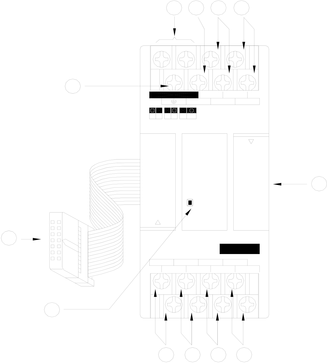
18.1.4FBs-6AD Hardware Description
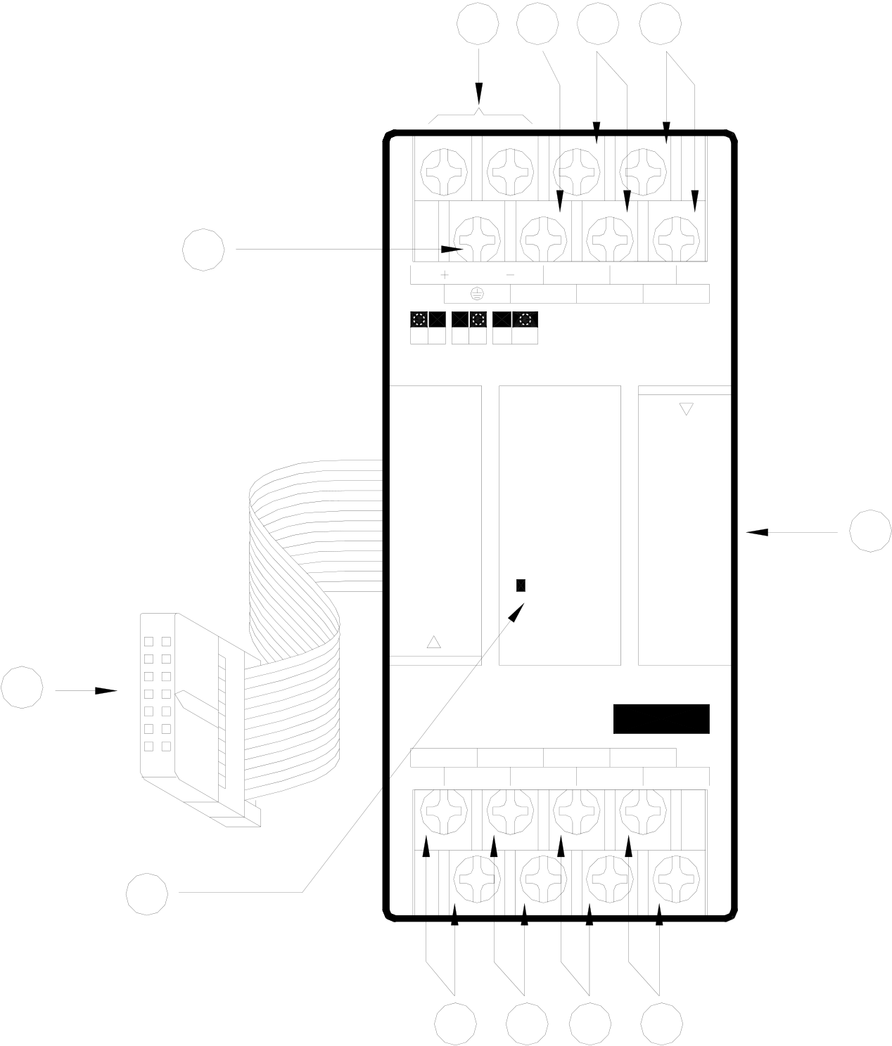
※ FBs-6AD contains 3 PCBs overlapping one
another. The lowest one is the power
|
2 |
V |
I |
24V IN |
AG |
I0+ I1+ I0-I1- |
supply unit (isolated power supply). The |
||
|
middle one is the I/O board (connectors |
||||||||
|
U |
B |
5V |
10V |
|||||
|
are on this layer). The upper one is the |
||||||||
control board (control/expansion I/O
connections) as described below.:
4
POW
|
3 |
FBs-6AD I2+ I3+ I4+ I5+ I2- I3- I4- I5- |
5
|
9 |
10 |
11 |
12 |
Outlook of top view
○1 External power input terminal :Power supply of analogue circuit for FBs-6AD, the voltage can be 24VDC±20% and
should be supplied with 4W of power at least.
○2 Protecting ground terminal:Connect to the shielding of the signal cable.
○3 Expansion input cable:It should be connected to the front expansion unit, or the expansion output of main unit.
○4 Expansion output connector:Provides the connection for next expansion unit.
○5 Power indicator: It indicates whether the power supply at analogue circuit and external input power source are
normal.
○6 AG Ground:No connection is needed in general; except when the common mode signal is too high. See examples
overleaf for details.
○7~○12 :Input terminal of CH0~CH5.
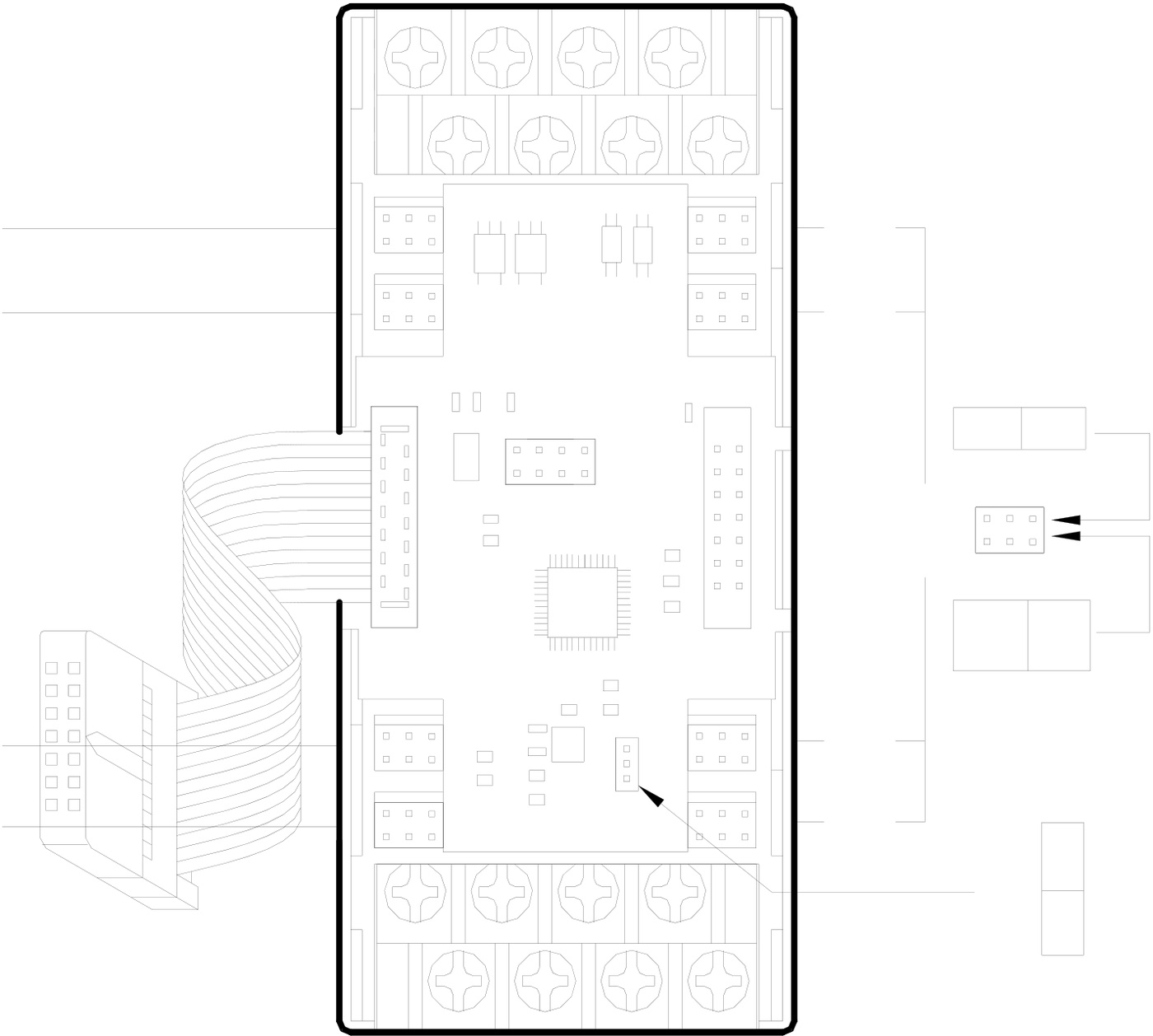
18.1.4.1 FBs-6AD Hardware Jumper Setting
|
JP5 |
V I |
|
B |
U |
JP1 |
JP4 |
V |
||
|
B |
I |
|||||
|
U |
JP2 |
5V |
10V
V
I
|
V |
JP7 |
JP8 |
V |
|
I |
I |
||
|
V |
JP6 |
JP9 |
V |
|
I |
I |
||
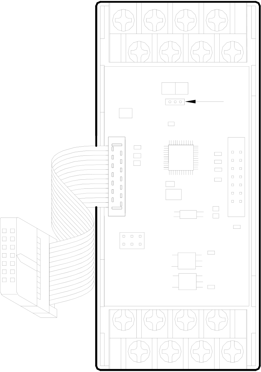
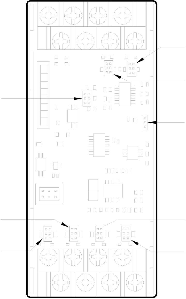
Pin layout in control board (open top cover)
Pin layout on I/O board (remove control board)







1. Input code format selection (JP1)
Users can select between unipolar and bipolar codes. The input range of unipolar codes and bipolar codes is 0~16383 and –8192~8191, respectively. The two extreme values of these formats correspond to the lowest and highest input signal values, respectively (see table below). For example, if the input signal type is set to -10V~ +10V, the unipolar code corresponding to the input is 8192 and the bipolar code corresponding to the input is 0 for 0V input. If the input is 10V, the unipolar code corresponding to the input is 16383 and the bipolar code corresponding to the input is 8191. In general, the input code format is selected according to the form of input signals; i.e. unipolar codes for unipolar input signals; and bipolar codes for bipolar input signals. In doing so, their correlations will become more heuristics. Unless it is necessary to make a deviation conversion through FUN33; otherwise, do not select bipolar codes for unipolar input signals (see FUN33 description for details). The format of input codes of all channels is selected from JP1. See above diagram for the location of JP1:
|



|
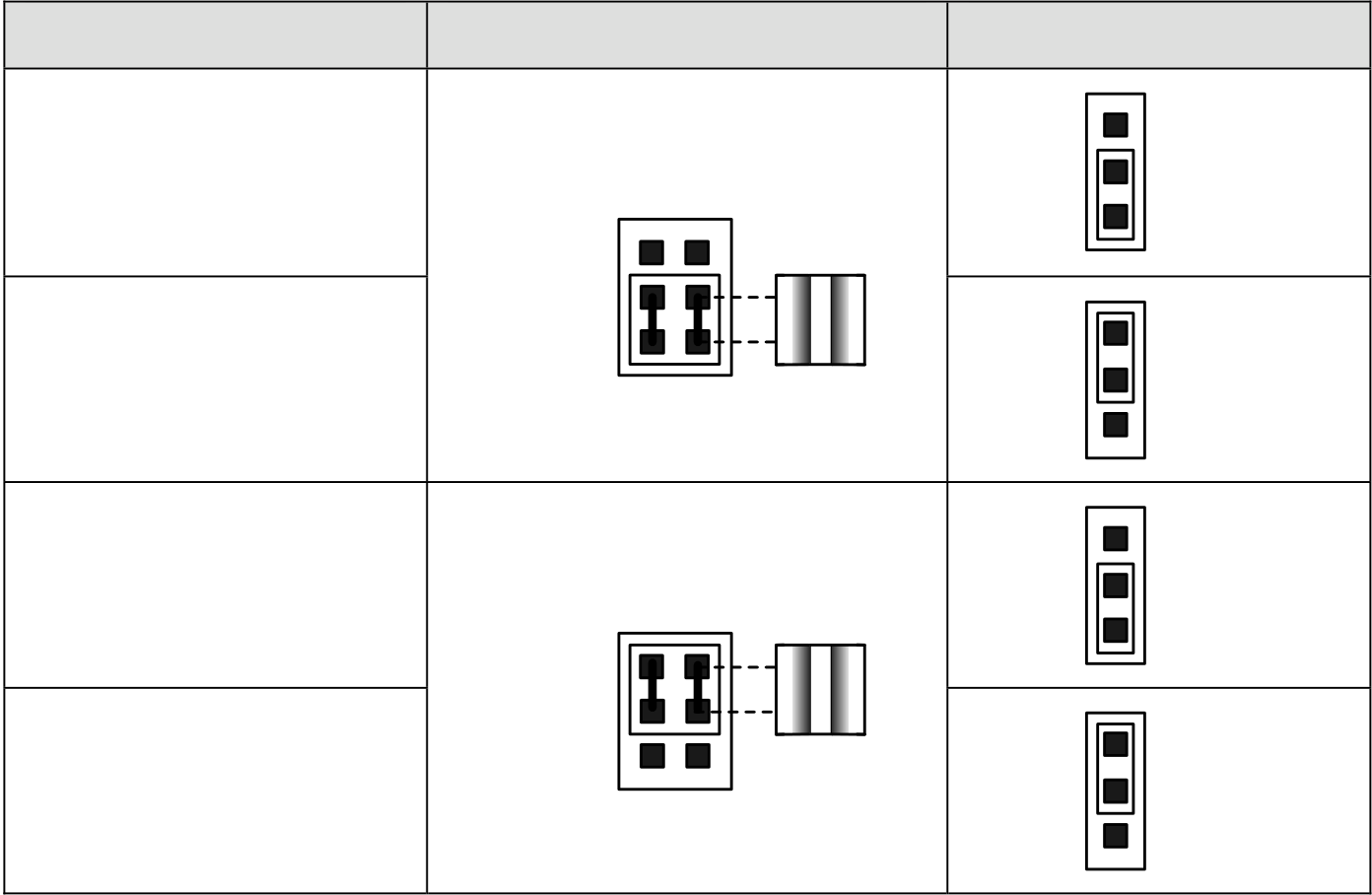
2. Input signal form setup (JP2&JP3) |
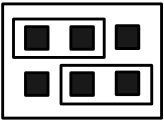
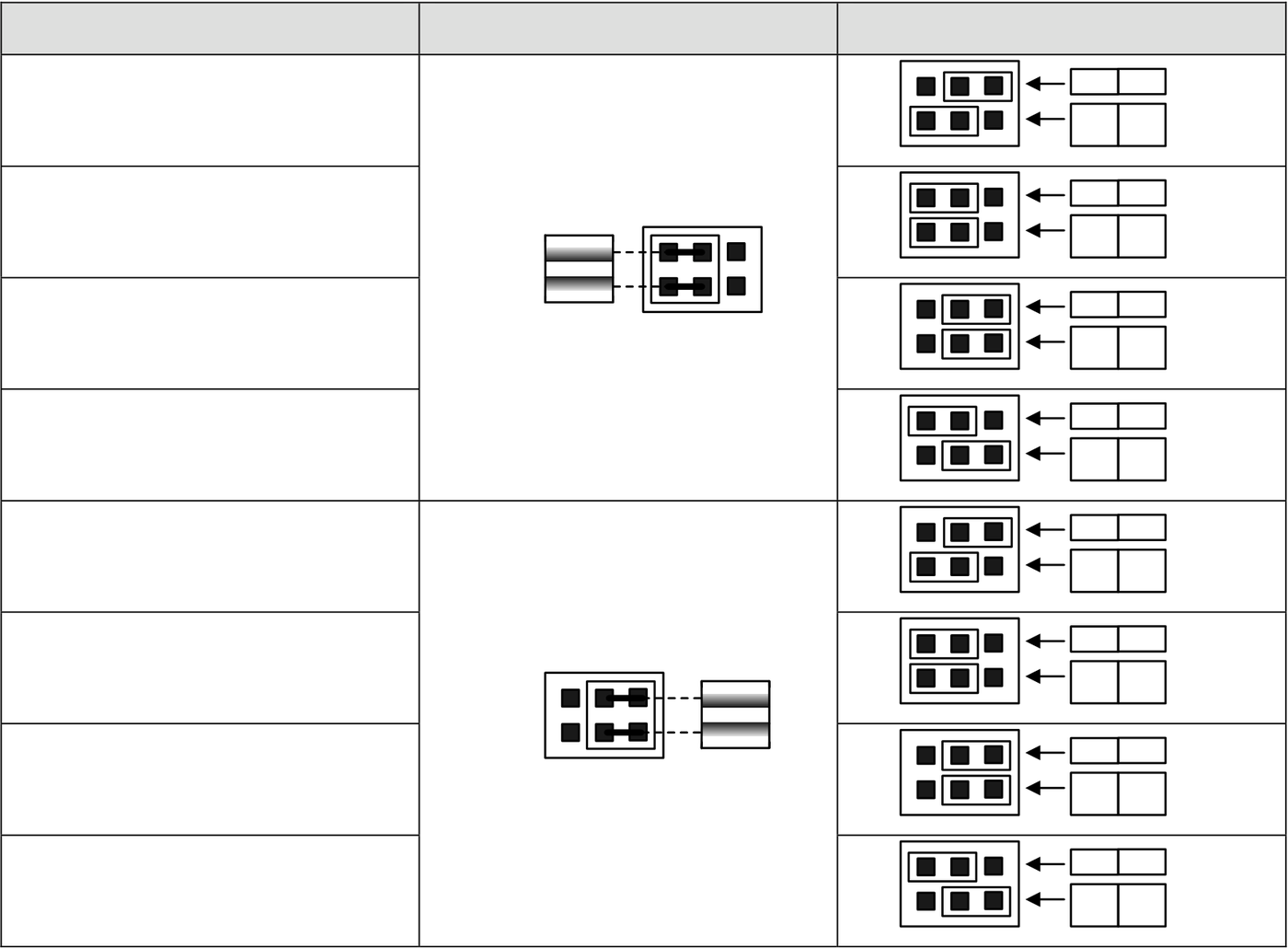
Users can set the input signal form (voltage/current) of individual channels; except the polarity and amplitude which are common. The location of jumpers are tabulated below:
|
Signal Form |
JP3 Setting |
JP2 Setting |
0~10V
or
0~20mA
0~5V
or
0~10mA
|
-10~+10V -20~+20mA -5~+5V -10mA~+10mA |
5V 5V |

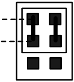
CH0~CH5 share the JP2 and JP3 jumper, therefore all channels must be of the same type that is one of the four types listed at above table. Only the current/voltage setting can be chosen arbitrary:
3. Voltage or current setting (JP4~JP9)
|
Signal Type |
JP4(CH0) ~ JP9(CH5) Setting |
||
|
Voltage |
|
||
|
Current |
|
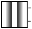
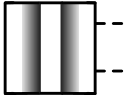
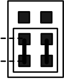
*The default factory settings of 6AD analogue input module are:
Input code format Æ Bipolar(-8192~+8191)
Input signal type and range Æ Bipolar(-10V ~ +10V)
For those applications that require the setting differ than the above default setting should make some modifications of jumper position according to above tables. While application, besides the setting of jumper should be conducted, the AI module configuration of WinProladder also need to be performed.
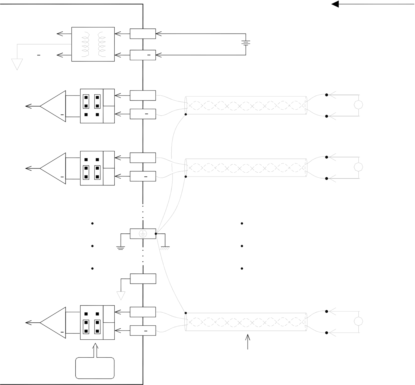
18.1.5FBs-6AD Input Circuit Diagram
|
FBs-6AD |
V |
24V+ |
+ |
24VDC |
Inputs |
||
|
+15V |
|||||||
|
15V |
24V |
External power supply |
V |
CH0 Input Ch0 Input (Voltage sou (Voltage Source) |
|||
|
+ |
I0+ |
||||||
|
I |
I0 |
||||||
|
+ |
V |
I1+ |
I |
CH1 Input Ch1 Input (Current sou (Current Source) |
|||
|
I1 |
|||||||
|
I |
|||||||
AG
|
+ |
I |
I5+ |
Twisted pair with shielding |
V |
CH5 Input Ch5 Input |
|
V |
I5 |
(Voltage sou (Voltage Source) |
|||
|
Voltage/ |
Current
selection
18.1.6FBs-6AD Input Characteristics and Jumper Setting
Users can select the Input ranges of FBs-6AD from the jumpers described above, such as V/I, U/B (I/O codes), U/B (signal form), 5V/10V, etc. The Input signals conversion characteristics of these settings are illustrated below. Users can adjust different Input forms by coordinating the conversion curve with various V/I (voltage/current) Input settings. See Section 18.1.4 for details of V/I settings :















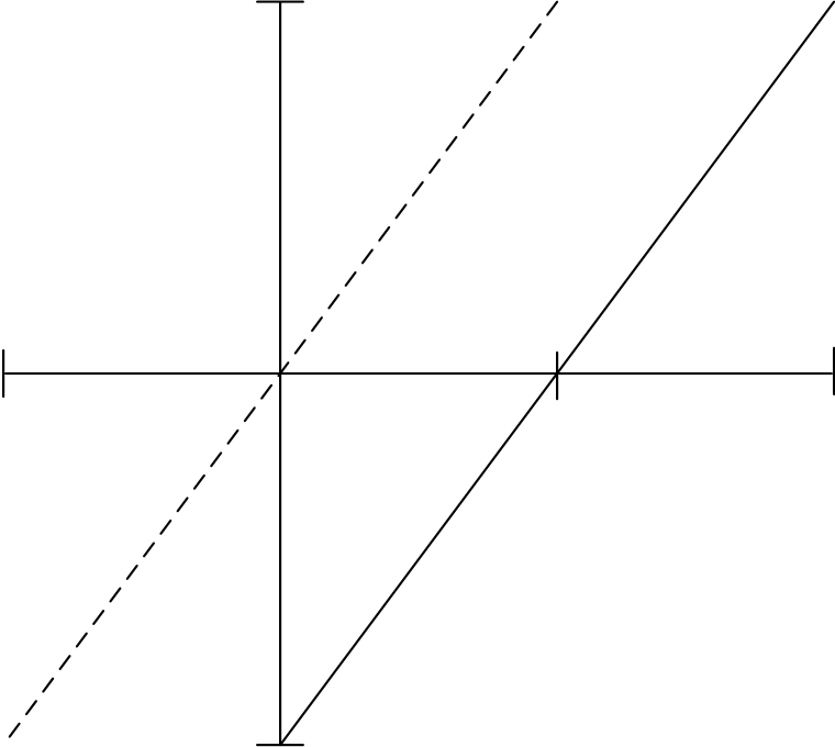
















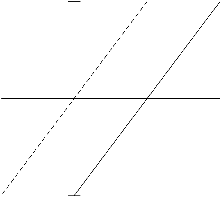








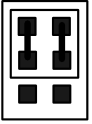




Diagram 1:Bipolar 10V(20mA)Span
|
Input |
Voltage |
−10V~10V |
Jumper |
|||||
|
Range |
Current |
−20mA~20mA Setting |
|
|
|
|
||



14 bit input format


|
|
|
|
|






|
|
|
|
|
|
|
|
|
|
|
|
12 bit input format |
|||||||||













|
|
|
|
|






|
|
|
|
|
|
|
|
|


























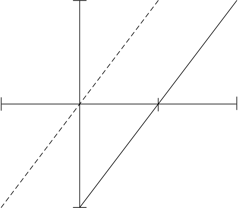




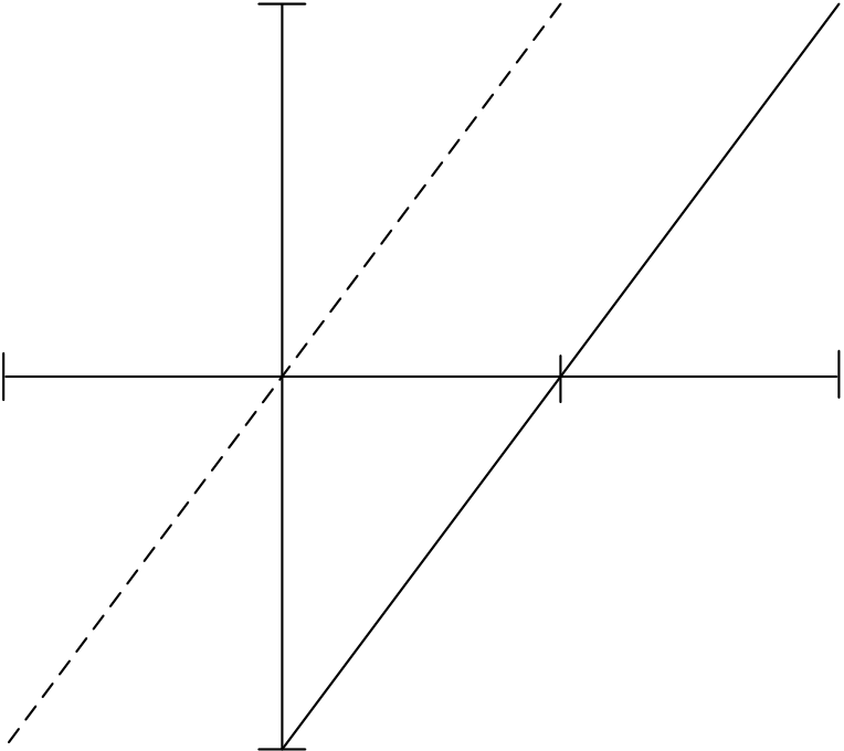

























Diagram 2:Bipolar 5V(10mA)Span
|




14 bit input format

|
|
|
|
|






|
|
|
|
|
|
|
|
|
|
12 bit input format |
|||||||










|
|
|
|
|






|
|
|
|
|
|
|
|
|
|
























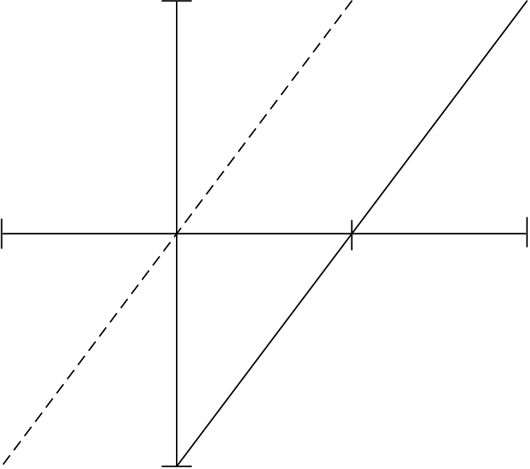

















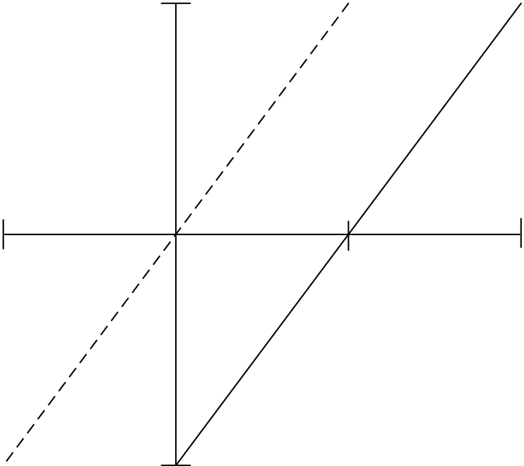










Diagram 3:Unipolar 10V(20mA)Span
|




14 bit input format

|
|
|
|
|






|
|
|
|
|
|
|
|
|
|
|
|
12 bit input format |
|||||||||












|
|
|
|





|
|
|
|
|
|
|
|
|
|










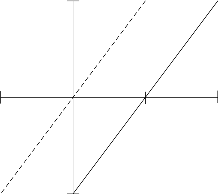






















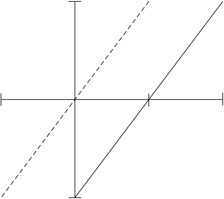
Diagram 4:Unipolar 5V(10mA)Span
|






14 bit input format

|
|
|
|
|






|
|
|
|
|
|
|
|
|
|
|
|
|
12 bit input format |
||||||||||












Analog Input(MAX.)
|
Input Register Value |
-2048 |
+5V(+10mA) |
Bipolar(B) |
Unipolar(U) |
|
0 |
+2047 |
+4095 |
||
|
(12 bit) |
0V(0mA)
Analog Input(Min.)
|
18.1.7 Configuration of Analog Input |
For the analog input reading of FBs series PLC, there are 3 kinds of data formats used to represent the reading value in compliance with the variation of the external analog inputs. Also, it supports the average method to improve the drift of the reading value away from the noise interference or unstable original analog signal.
The WinProladder provides the friendly and convenient operation interface for the purpose of analog input configuration. There are "analog input data format", "valid bits", and "number of average" for settings.
The procedures for analog inputs configuration with WinProladder
Click the item “I/O Configuration” which in Project Windows :
|
Project name |
||||||
|
S |
stem Co |
nfigurat |
on |
|||
I/O Configuration Æ Select “AI Configuration”
● If FBs main unit connects with AD Expansion nodule, then it will auto detect and allotted the system resource(IR).
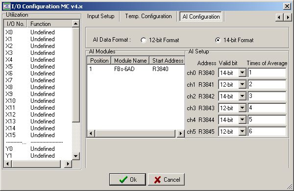
Description of the configuration screen:
● AI Data Format :All analog inputs can be assigned as 12-bit or 14-bit resolution of data format.
● AI Modules :This window displays the information of installed analog input modules, click the selective module will
bring the setting window for valid bits and times of average.
● AI Setup :When the data format is 12-bit resolution, each channel of analog input can be allowed to set the times
of average; When the data format is 14-bit resolution, each channel of analog input can be allowed to
set the valid bits and times of average.
AI Data Format
● 12-bit resolution with sign representation (-2048~2047):
|
B15 |
B14 |
B13 |
B12 |
B11 |
B10 |
B9 |
B8 |
B7 |
B6 |
B5 |
B4 |
B3 |
B2 |
B1 |
B0 |
|
B11 |
B11 |
B11 |
B11 |
0/1 |
0/1 |
0/1 |
0/1 |
0/1 |
0/1 |
0/1 |
0/1 |
0/1 |
0/1 |
0/1 |
0/1 |
*B11 = 0———Positive reading value
1——— Negative reading value
*B15~B12 = B11
● 12-bit resolution without sign representation(0~4095):
|
B15 |
B14 |
B13 |
B12 |
B11 |
B10 |
B9 |
B8 |
B7 |
B6 |
B5 |
B4 |
B3 |
B2 |
B1 |
B0 |
|
0 |
0 |
0 |
0 |
0/1 |
0/1 |
0/1 |
0/1 |
0/1 |
0/1 |
0/1 |
0/1 |
0/1 |
0/1 |
0/1 |
0/1 |
● 14-bit but valid 12-bit resolution with sign representation (-8192~8188):
|
B15 |
B14 |
B13 |
B12 |
B11 |
B10 |
B9 |
B8 |
B7 |
B6 |
B5 |
B4 |
B3 |
B2 |
B1 |
B0 |
|
B13 |
B13 |
0/1 |
0/1 |
0/1 |
0/1 |
0/1 |
0/1 |
0/1 |
0/1 |
0/1 |
0/1 |
0/1 |
0/1 |
0 |
0 |
*B13 = 0——— Positive reading value
1——— Negative reading value
*B15~B14= B13 ; B1~B0= 0
*In this Data Format, because B1 and B0 are fixed 0 then value change by times of 4.
● 14-bit but valid 12-bit resolution without sign representation (0~16380):
|
B15 |
B14 |
B13 |
B12 |
B11 |
B10 |
B9 |
B8 |
B7 |
B6 |
B5 |
B4 |
B3 |
B2 |
B1 |
B0 |
|
0 |
0 |
0/1 |
0/1 |
0/1 |
0/1 |
0/1 |
0/1 |
0/1 |
0/1 |
0/1 |
0/1 |
0/1 |
0/1 |
0 |
0 |
*In this Data Format, because B1 and B0 are fixed 0 then value change by time of 4.
● 14-bit resolution with sign representation (-8192~8191):
|
B15 |
B14 |
B13 |
B12 |
B11 |
B10 |
B9 |
B8 |
B7 |
B6 |
B5 |
B4 |
B3 |
B2 |
B1 |
B0 |
|
B13 |
B13 |
0/1 |
0/1 |
0/1 |
0/1 |
0/1 |
0/1 |
0/1 |
0/1 |
0/1 |
0/1 |
0/1 |
0/1 |
0/1 |
0/1 |
*B13 = 0——— Positive reading value
1——— Negative reading value
*B15~B14= B13
● 14-bit resolution without sign representation (0~16383):
|
B15 |
B14 |
B13 |
B12 |
B11 |
B10 |
B9 |
B8 |
B7 |
B6 |
B5 |
B4 |
B3 |
B2 |
B1 |
B0 |
|
0 |
0 |
0/1 |
0/1 |
0/1 |
0/1 |
0/1 |
0/1 |
0/1 |
0/1 |
0/1 |
0/1 |
0/1 |
0/1 |
0/1 |
0/1 |
Relative registers of AI configuration
This introduction is for HMI or SCADA User, because they may modify through registers. Winprolader’s User can
ignore this introduction. When you configure Analog Input format with Winproladder, these value of registers will be
finished.
|
Register |
Content |
Description |
|
D4042 |
5612H |
all analog inputs are the 12-bit resolution ; it is allowed to set times of average for each channel. |
|
〃 |
5614H |
all analog inputs are the 14-bit resolution ; it is allowed to set times of average for each channel. |
|
Register |
Content |
Description |
|
D4006 |
B0 = 0 |
AI channel 0 is valid 12-bit resolution. |
|
B0 = 1 |
AI channel 0 is valid 14-bit resolution. |
|
|
〃 |
● |
● |
|
D4006 |
B15 = 0 |
AI channel 15 is valid 12-bit resolution. |
|
B15 = 1 |
AI channel 15 is valid 14-bit resolution. |
|
|
D4007 |
B0 = 0 |
AI channel 16 is valid 12-bit resolution. |
|
B0 = 1 |
AI channel 16 is valid 14-bit resolution. |
|
|
〃 |
● |
● |
|
D4007 |
B15 = 0 |
AI channel 31 is valid 12-bit resolution. |
|
B15 = 1 |
AI channel 31 is valid 14-bit resolution. |
|
|
Register |
Content |
Description |
|
D4008 |
B0 = 0 |
AI channel 32 is valid 12-bit resolution. |
|
B0 = 1 |
AI channel 32 is valid 14-bit resolution. |
|
|
〃 |
● |
● |
|
D4008 |
B15 = 0 |
AI channel 47 is valid 12-bit resolution. |
|
B15 = 1 |
AI channel 47 is valid 14-bit resolution. |
|
|
D4009 |
B0 = 0 |
AI channel 48 is valid 12-bit resolution. |
|
B0 = 1 |
AI channel 48 is valid 14-bit resolution. |
|
|
〃 |
● |
● |
|
D4009 |
B15 = 0 |
AI channel 63 is valid 12-bit resolution. |
|
B15 = 1 |
AI channel 63 is valid 14-bit resolution. |
|
|
Register |
Content |
Description |
|
D4010 |
1~16 |
Low byte is used to define the times of average for AI channel 0. |
|
1~16 |
High byte is used to define the times of average for AI channel 1. |
|
|
● |
● |
● |
|
D4041 |
1~16 |
Low byte is used to define the times of average for AI channel 62. |
|
1~16 |
High byte is used to define the times of average for AI channel 63. |
※ The default of AI data format is 14-bit resolution, valid 12-bit, and times of average is 1.
※ The legal setting value for times of average is 1~16, if it is not the value :
The default for times of average is 1 when it is valid 12-bit resolution. The default for times of average is 8 when it is valid 14-bit resolution.
|
18.1.8Tacking on the OFFSET Mode Input |
For the process of input for signal source of offset mode (take 4~20mA input for example), the user can set A/D input range to be 0 ~20mA, convert the IR value to unipolar (0 ~16383), lessen the offset (4mA) value (16383×4/20=3276), then times the maximum input amount (20mA), and divide by the maximum span (4mA~20mA); and it can acquire the offset input conversion from 4mA~20mA reflect to 0~16383, the procedure is as follows :
a. Set the A/D input range of analogue input module to be 0~20mA.
|
b. Add the IR (R3840~R3903) value with |
*8192 and then store it into register Rn (the value of Rn is 0~16383). |
|
c. Deduct 3276 (16383x 20 4) from value of register Rn, and store the calculated value back to register Rn; if the value is |
|
negative, clear the content of register Rn to 0 (the value of Rn is 0~13107).
d. The value of register Rn times 20 and then divide by 16 (Rn x 16 20), and it will convert the 4mA~20mA input to
range of 0~16383.
e. To sum up the items from a~d, the mathematical equation is as follows:
Offset mode conversion value =[IR+8192(or 0) −(16383×20 4)]×16 20;value is 0~16383
※ Special to 4~20 mA Offset mode, you can use FUN32 to substitute for processing above, but another offset mode
please refer to above processing.
*note : Step b “Add 8192” is means input code setting in bipolar mode( JP1 setting in position B). If input code setting in
unipolar mode (JP1 setting in position U) then you don’t have to “Add 8192”.
Using Linear Conversion(FUN33) reading on 4~20mA OFFSET mode
Except using the above mathematical methods and FUN32 to read 4~20mA analog reading conversion, when the OS version is later than 4.08 (including), you may use linear conversion instruction (FUN33) to read 4~20mA conversion input parameters.
|
• When M0 is “ON”, it will continuous perform |
|||||||
|
|
|
|
|
|
6 registers of conversion starting from R0, |
||
|
where R1000 is the starting address of the |
|||||||
|
table of the conversion parameters, and the |
|||||||
|
corresponding values will be stored into |
|||||||
|
R50~R55. |





The converted result is in below:
Ts
|
R1000 |
3276 |
|
R1001 |
16383 |
|
R1002 |
0 |
|
R1003 |
16383 |
S D
|
R0 |
0 |
R50 |
-4094 |
|
|
R1 |
3000 |
R51 |
-345 |
|
|
R2 |
6000 |
R52 |
3405 |
|
|
R3 |
9000 |
Ö |
R53 |
7155 |
|
R4 |
12000 |
R54 |
10904 |
|
|
R5 |
16383 |
R55 |
16383 |
|
18.2 FBs-4DA/2DA Analog Output Module |
FBs-4DA and FBs-2DA are two of the analog output modules of FATEK FBs series PLC. They provide 4 and 2 channels 14 bits D/A output respectively. Base on the different jumper settings it can provide varieties of current or voltage output signal. The output code can be configured as unipolar or bipolar which makes the relation of output code and real output signal more intuitive. For safety, the output signal will be automatically forced to zero(0V or 0mA) when the module is not serviced by CPU for 0.5 second.
|
18.2.1 Specifications of FBs-4DA/2DA |
|
Item |
Specifications |
Remark |
||
|
Total Channel |
4 Channel(FBs-4DA)、2 Channel(FBs-2DA) |
|||
|
Digital Output Value |
−8192~+8191(Bipolar) or 0~16383(Unipolar) |
*:It means the default setting |
||
|
Span output |
Bipolar* |
*10V |
*1. Voltage:−10~10V 5. Current:−20~20mA |
|
|
5V |
2. Voltage:−5~5V 6. Current:−10~10mA |
|||
|
Unipolar |
10V |
3. Voltage:0~10V 7. Current:0~20mA |
||
|
5V |
4. Voltage:0~5V 8. Current:0~10mA |
|||
|
Resolution |
14 bits |
|||
|
Finest resolution |
0.3mV(Voltage)、0.61µA(Current) |
|||
|
I/O Points Occupied |
4(4DA) or 2(2DA) OR(Output register) |
|||
|
Accuracy |
Within ±1% of full scale |
|||
|
Conversion Time |
Updated each scan |
|||
|
Maximum accommodation for resistance loading |
Voltage:500Ω~1MΩ |
The deviation will be |
||
|
Isolation |
Transformer(Power) and photocouple(Signal) |
|||
|
Indicator(s) |
5VPWR LED |
|||
|
Internal Power Consumption |
5V、20mA |
|||
|
Operating Temperature |
0~60 ℃ |
|||
|
Storage Temperature |
-20~80 ℃ |
|||
|
External power supply |
24V-15%/+20%、120mA(4DA)、70mA(2DA) |
|||
|
Dimensions |
40(W)x90(H)x80(D) mm |
|||
|
18.2.2The Procedure of Using FBs-4DA/2DA Analog Output Module |
Start
Set the I/O voltage/current (V/I), polarity (B/U), and the V/I
range of each point before installation. Connect FBs-4DA/2DA to the expansion interface on PLC in series and connect an external 24VDC source and analog output wires to the module.
Directly fill the output value into the analogue output registers R3904~R3967 to acquire the corresponding analogue output span of CH0~CH63 from output module.
End
——-Please refer to section 18.2.4 for hardware explanation.
|
18.2.3 Address Allocation of FBs-PLC Analog Outputs |
FBs-4DA/2DA Provides 4 points of outputs(4DA) or 2 points of outputs(2DA). The I/O addressing of output is beginning from the module closest to main unit; it is orderly numbered as CH0~CH1 (1st module), CH2~CH3 (2nd module), CH4~CH5 (3rd module)…… and increased with occurring order number, which reaches 64 points in total, and they are corresponding to the respective internal analogue output registers (so called OR register) R3904~R3967. User needs only to expand connecting FBs-DA modules through expansion interface, and main unit will automatically detect the quantity of the outputs and send out the value to corresponding output of each DA modules. The following table is detailed OR registers (R3904~R3967) corresponding to the expansion analogue outputs (CH0~CH63). WinProladder will automatically detect and calculate the ORs on the system after connecting to the PLC. Users may refer to the I/O Module Number Configuration provided by WinProladder in order to find out the exact I/O address of each expansion module to facilitate programming.
I/O allocation of FBs-2DA
|
Numeric Output |
Contents (CH0~CH63) |
Output lable |
FBs-2DA |
|
|
Register(OR) |
B 1 5 B1 4B 1 3 B1 2 B 11 B 1 0 B9 B 8 B 7 B 6 B 5 B 4 B3 B 2 B 1 B 0 |
Of FBs-2DA |
||
|
OR+0 |
**B 1 3 CH0output valueB 0 |
CH0 |
||
|
OR+1 |
** |
CH1output value |
CH1 |
FBs-2DA |
|
OR+2 |
** |
CH2output value |
CH0 |
|
|
OR+3 |
** |
CH3output value |
CH1 |
|
Other modules
|
R3966 |
Depends on module type |
CHX |
|
R3967 |
Depends on module type |
CHX |
* *———— Unipolar code output (0~16383),B14、B15 = 00
Bipolar code output (-8192~8191),B14、B15 = B13
|
I/O allocation of FBs-4DA |
||||
|
Numeric Output |
Contents (CH0~CH63) |
Output lable |
FBs-4DA |
|
|
Register(OR) |
B 1 5 B1 4B 1 3 B1 2 B 11 B 1 0 B9 B 8 B 7 B 6 B 5 B 4 B3 B 2 B 1 B 0 |
Of FBs-4DA |
||
|
OR+0 |
**B 1 3 CH0output valueB 0 |
CH0 |
||
|
OR+1 |
** |
CH1output value |
CH1 |
|
|
OR+2 |
** |
CH2output value |
CH2 |
Other modules |
|
OR+3 |
** |
CH3output value |
CH3 |
|
|
R3964 |
Depends on module type |
CHX |
||
|
R3965 |
Depends on module type |
CHX |
|
R3966 |
Depends on module type |
CHX |
|
R3967 |
Depends on module type |
CHX |
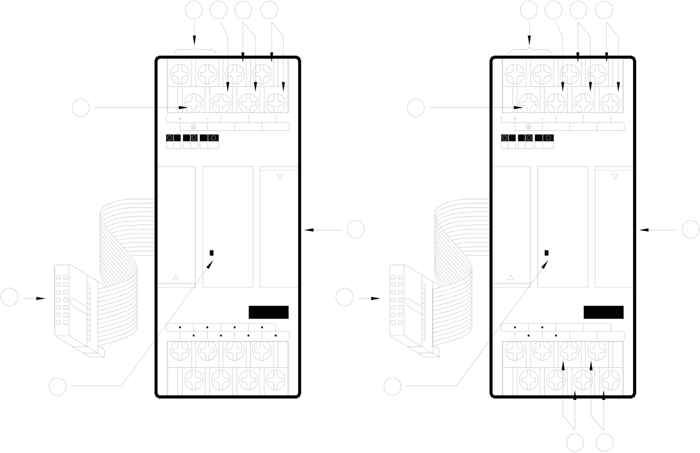
|
18.2.4 FBs-2DA /4DA Hardware Description |
|
2 |
1 |
6 |
7 |
8 |
2 |
1 |
6 |
7 |
8 |
||
|
24V IN |
AG |
O0+ O1+ O0- |
O1- |
24V IN |
AG |
O0+ O1+ O0- |
O1- |
||||
V I UB5V 10V V I UB 5V 10V
4 4
POW POW
3 3
FBs-2DA FBs-4DA
O2+ O3+
O2- O3-
5 5
9 10
FBS-2DA FBS-4DA
○1External power input terminal:Power supply of analogue circuit for this module, the voltage can be 24VDC±20% and
should be supplied with 4W of power at least.
○2Protecting ground terminal:Connect to the shielding signal cable.
○3Expansion input cable:It should be connected to the front expansion unit, or the expansion output of main unit.
○4Expansion output connector:Provides the connection for next expansion unit.
○5Power indicator:It indicates whether the power supply at analogue circuit and external input power source are
normal.
○6AG Ground:No connection is needed in general; except when the common mode signal is too high. See examples
overleaf for details.
○7、○8:Output terminal of CH0~CH1.
○9、○10 :Output terminal of CH2~CH3.
|
18.2.4.1 FBs-4DA/2DA Hardware Jumper Setting |
|
CH0 |
CH0 |
|
V |
I |
CH1 |
CH1 |
JPB |
B |
U |
|
|
|
|
|
JPA |
CH2 |
10V |
5V |
|
|
|
|
|
|||||
|
CH2 |
|||||||
|
CH3 |
CH3 |
JP1 |
U |
||||


B
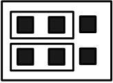
FBs-4DA/2DA Jumper location
Output code format selection (JP1)
Users can select between unipolar and bipolar codes. The output range of unipolar codes and bipolar codes is 0~16383 and –8192~8191, respectively. The two extreme values of these formats correspond to the lowest and highest output signal values, respectively (see table below). In general, the output code format is selected according to the form of output signals; i.e. unipolar codes for unipolar output signals; and bipolar codes for bipolar output signals. In doing so, their correlations will become more heuristics. Yet, as the format of output code on all channels is selected from JP1, it is the user’s choice to select unipolar or bipolar codes if both are used on different channels. See diagram above for location of JP1 :
|










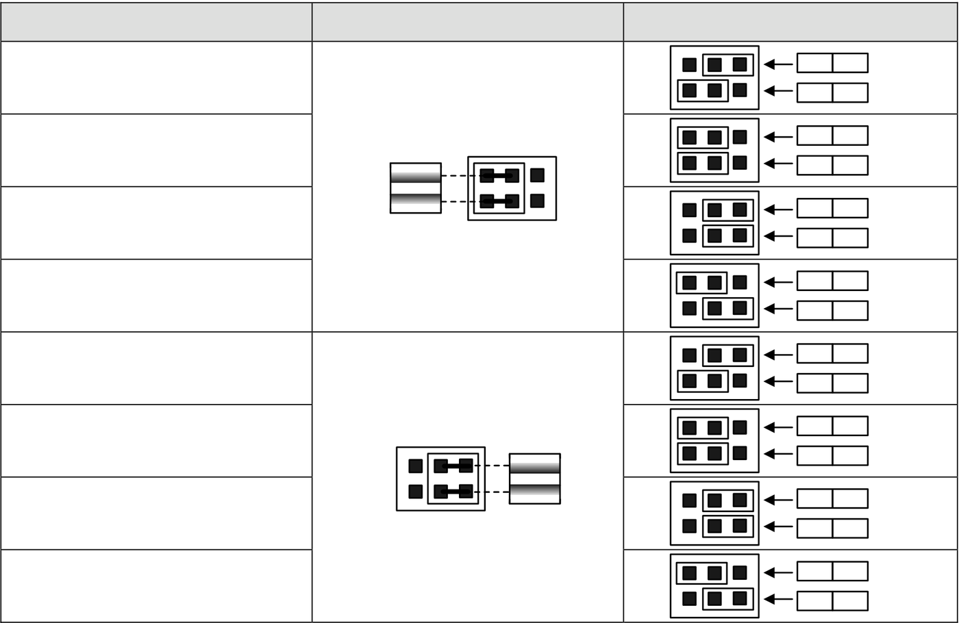
Output signal form setup (JPA&JPB)
Users can set the output signal form (voltage/current) of individual channels; except the polarity and amplitude which
are common.
|
Signal Form |
JPA (voltage/current) Setting |
JPB (polarity/amplitude) Setting |
0V~10V
-10V~10V
0V~5V
-5V~5V
0mA~20mA
-20mA~20mA
0mA~10mA
-10mA~10mA
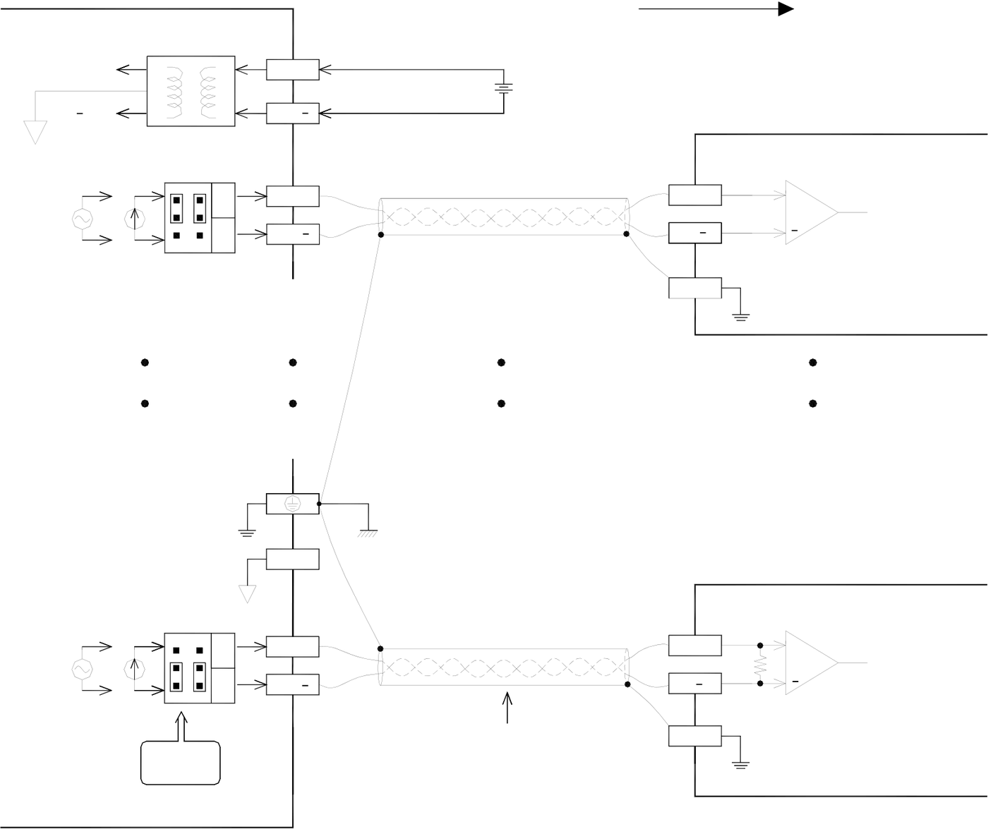
18.2.5 FBs-4DA/2DA Output Circuit Diagram
|
FBs-4DA/2DA |
V |
24V+ |
Output |
+ |
||
|
+ |
24VDC |
|||||
|
+15V |
||||||
|
15V |
24V |
External power supply |
||||
|
O0+ |
CH0 Voltage output |
V+ |
||||
|
I |
O0 |
V |
||||
Voltage Input
FG
AG
|
V |
On+ |
CHn Current output |
I+ |
+ |
|
On |
I |
|||
|
I |
Current Input
|
Voltage/ |
Twisted pair with shielding |
FG |
Current output
selection
n = 1 — 2DA
n = 3 — 4DA

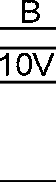









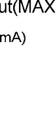











|
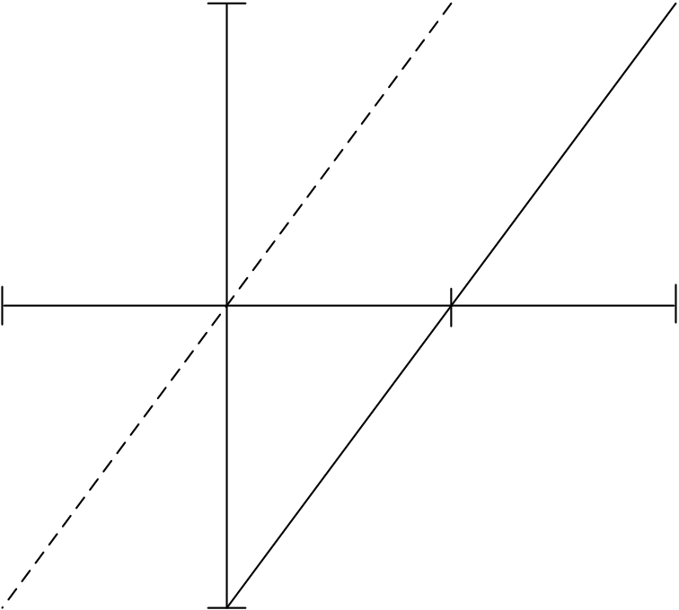
18.2.6 FBs-4DA/2DA Output Characteristics and Jumper Setting |
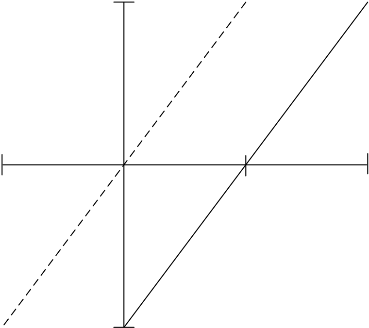
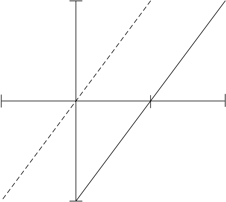
Users can select the output ranges of FBs-4DA/2DA from the jumpers described above, such as V/I, U/B (I/O codes), U/B (signal form), 5V/10V, etc. The Output signals conversion characteristics of these settings are illustrated below. Users can adjust different Output forms by coordinating the conversion curve with various V/I (voltage/current) Output settings. See Section 18.2.4 for details of V/I settings :
Diagram 1:Bipolar 10V(20mA)Span
|









|
|
|
|
|
|
|
|
|
|
|
|||||||
|
|














Diagram 2:Bipolar 5V(10mA)Span
|











































|
|
|
|
|
|
|
|
|
|
|
|||||||
|
|












Diagram 3:Unipolar 10V(20mA)Span
|








|
|
|
|
|
|
|
|
|
|
|
|
|
|||||||||
|
|



















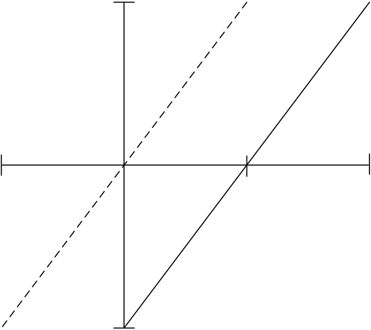









Diagram 4:Unipolar 5V(10mA)Span
|
||||||||||||||||||||||||||||||||||||||||||||||||
|
|
|
|
|
|||||||||||||||||||||||||||||||||||||||||||||
|
|
|
|
|
|||||||||||||||||||||||||||||||||||||||||||||




















|
18.2.7Tracking on the OFFSET Mode Output |
For the process of output for signal source of offset mode (take 4~20mA output for example), when the OS version is later than 4.08 (including), you may use linear conversion instruction (FUN33) to read 4~20mA conversion output parameters.
|
•When M0 is “ON”, it will continuous perform 6 |
||||||||
|
|
|
registers of conversion starting from R0, |
||||||
|
where R1000 is the starting address of the |
||||||||
|
table of the conversion parameters, and the |
||||||||
|
corresponding values will be stored into |
||||||||
|
R50~R55. |






The converted result is in below:
Ts
|
R1000 |
|
S D
|
R0 |
|
Ö |
R50 |
|
||||||||||||
|
R1 |
R51 |
|||||||||||||||
|
R2 |
R52 |
|||||||||||||||
|
R3 |
R53 |
|||||||||||||||
|
R4 |
R54 |
|||||||||||||||
|
R5 |
R55 |
18.3 FBs-4A2D Analog Input/Output Module
FBs-4A2D is one of the analog I/O modules of FATEK FBs series PLC. For analog output it provides 2 channels of 14 bit D/A output. Base on the different jumper settings it can provide varieties of current or voltage output signal. The output code can be configured as unipolar or bipolar which makes the relation of output code and real output signal more intuitive. For safety, the output signal will be automatically forced to zero(0V or 0mA) when the module is not serviced by CPU for 0.5 second.
For analog input it provides 4 channels A/D input with 12 or 14 bits effective resolution. Base on the different jumper settings it can measure the varieties of current or voltage signal. The reading value is represented by a 14 bit value no matter the effective resolution is set to 12 or 14 bits The output code also can be configured as unipolar or bipolar which makes the relation of input code and real input signal more intuitive.. In order to filter out the field noise imposed on the signal, it also provides the average of sample input function.
|
18.3.1 Specifications of FBs-4A2D |
|
Analog output specifications |
|
Item |
Specifications |
Remark |
||
|
Output Channel |
2 Channel (2DA) |
|||
|
Digital Output Value |
−8192~+8191(Bipolar) or 0~16383(Unipolar) |
*:It means the default setting |
||
|
Span Of output |
Bipolar* |
*10V |
*1. Voltage:−10~10V 5. Current:−20~20mA |
|
|
5V |
2. Voltage:−5~5V 6. Current:−10~10mA |
|||
|
Unipolar |
10V |
3. Voltage:0~10V 7. Current:0~20mA |
||
|
5V |
4. Voltage:0~5V 8. Current:0~10mA |
|||
|
Resolution |
14 bits |
|||
|
Finest resolution |
0.3mV(Voltage)、0.61µA(Current) |
|||
|
I/O Points Occupied |
2 OR(Output register) |
|||
|
Accuracy |
Within ±1% of full scale |
|||
|
Conversion Time |
Updated each scan |
|||
|
Maximum accommodation for resistance loading |
Voltage:500Ω~1MΩ |
The deviation will be |
||
|
Analog input specifications |
|
Item |
Specifications |
Remark |
||
|
Input Channel |
4 Channel (4AD) |
|||
|
Digital Input Value |
−8192~+8191or 0~16383(14bit) −2048~+2047or 0~4095(12bit) |
|||
|
Span |
Bipolar* |
*10V |
*10V *1. Voltage:−10~10V 5. Current:−20~20mA |
*:It means the default setting |
|
5V |
2. Voltage:−5~5V 6. Current:−10~10mA |
|||
|
Unipolar |
10V |
3. Voltage:0~10V 7. Current:0~20mA |
||
|
5V |
4. Voltage:0~5V 8. Current:0~10mA |
|||
|
Resolution |
14 or 12 bit |
|||
|
Finest resolution |
Voltage:0.3mV |
=Analog Input Signal/ |
|
I/O Points Occupied |
4 IR(Input register) |
|
|
Accuracy |
Within ±1% of full scale |
|
|
Conversion Time |
Updated each scan |
|
|
Maximum absolute input signal |
Voltage:±15V(max) |
It may cause the |
|
Input resistance |
63.2KΩ(Voltage input)、250Ω(Current Input) |
General specifications
|
Isolation |
Transformer(Power) and photocouple(Signal) |
|
|
Indicator(s) |
5VPWR LED |
|
|
Internal Power Consumption |
5V、100mA |
|
|
External power supply |
24V-15%/+20%、100mA |
|
|
Operating Temperature |
0 ~ 60 ℃ |
|
|
Storage Temperature |
-20 ~ 80 ℃ |
|
|
Dimensions |
40(W)x90(H)x80(D) mm |
|
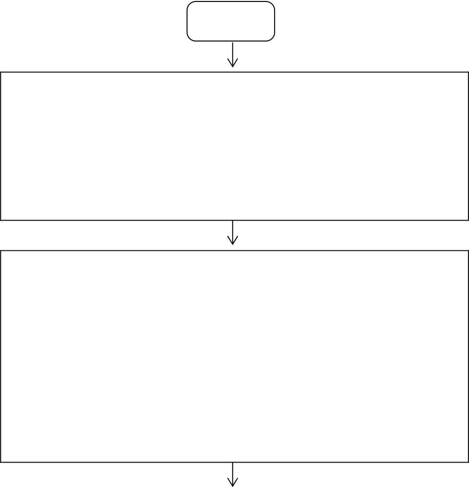
18.3.2 The Procedure of Using FBs-4A2D Analog Input/Output Module |
Start
Set the I/O voltage/current (V/I), polarity (B/U), and the V/I
range of each point before installation. Connect FBs-4A2D to the expansion interface on PLC in series and connect an external 24VDC source and analog output wires to the module.
Analog Input : Directly read the value of the four corresponding IRs to obtain the analog input reading of CH0~CH3.
Analog Output : Directly fill the output value into the analogue output registers R3904~R3967 to acquire the
——-Please refer to section 18.3.4 for hardware explanation.
corresponding analogue output span of CH0~CH1 from
output module.
End
|
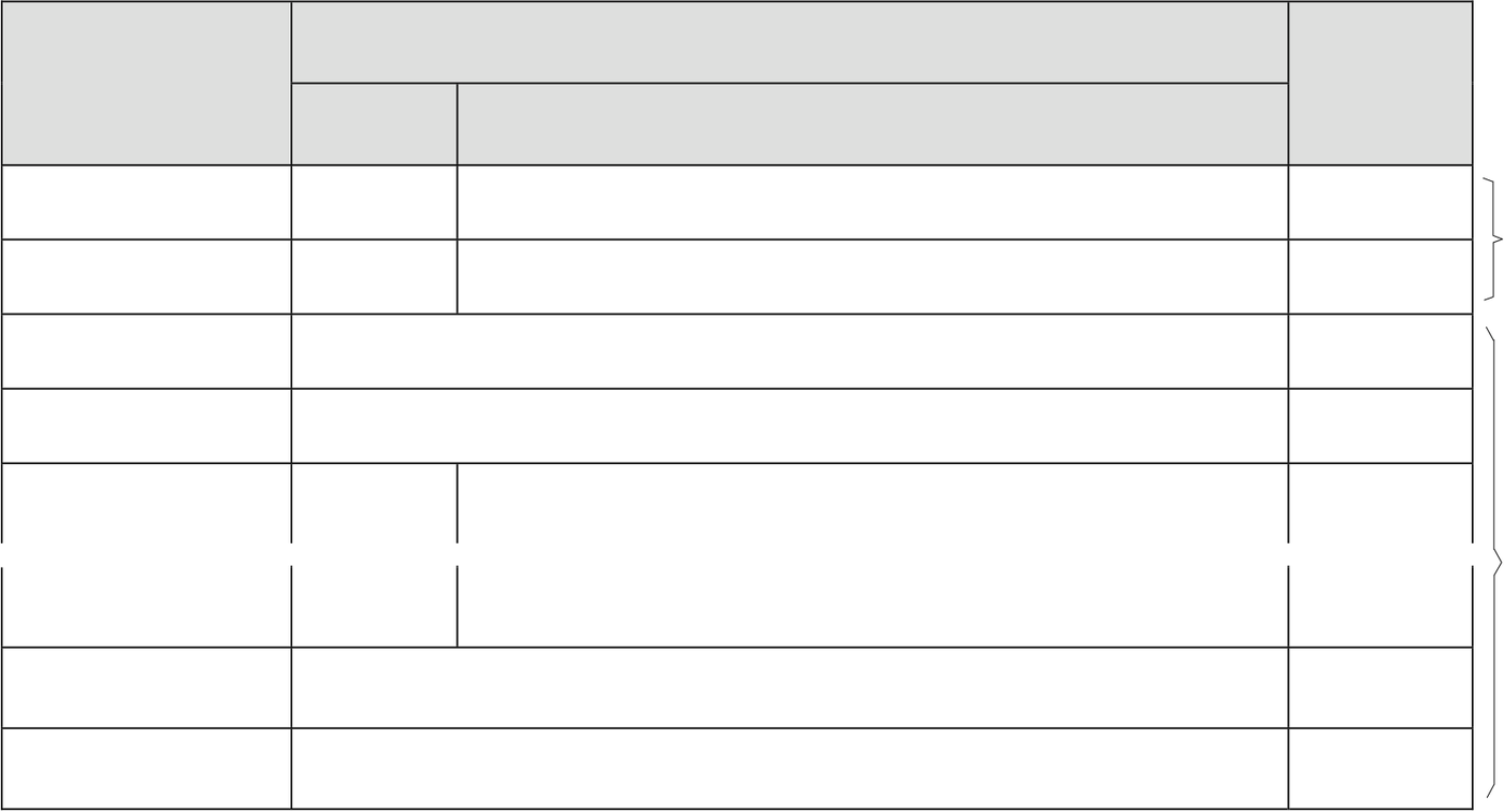
18.3.3 Address Allocation of FBs-PLC Analog Inputs/Outputs |
FBs-4A2D offers 4 AD points and 2 DA points. The AD points number starts from the one nearest to the PLC, the number in order is CH0~CH3 (module 1); CH4~CH7 (module 2); CH8~CH11 (module 3); etc, accumulates in serial; i.e. add 4 to each module, the total is 64 points (CH0~CH63) corresponding top the value IRs inside the PLC (R3840~R3903), respectively. In DA point numbering, from the one nearest to the PLC, the number runs from CH0 through to CH63 in serial, the total is 64 points corresponding top the value ORs inside the PLC (R3904~R3967), respectively. After connecting FBs-4A2D to the expansion interface on the PLC, FBs-PLC will automatically detect the number of AD/DA points. WinProladder will automatically detect and calculate the value IRs/ORs on the system after connecting to the PLC. Users may refer to the I/O Module Number Configuration provided by WinProladder in order to find out the exact I/O address of each expansion module to facilitate programming (see I/O Number Configuration, Section 12.6, WinProladder User’s Manual for details).
Address allocation of FBs-4A2D(Analog output)
|
Numeric Output |
Content of OR (CH0~CH63) |
Output |
FBs-4A2D |
|
|
Register(OR) |
B 15 B 1 4B 1 3 B1 2 B 11 B 1 0 B9 B 8 B 7 B 6 B 5 B 4 B3 B 2 B 1 B 0 |
lable |
||
|
OR+0 |
** |
B 1 3 CH0 output valueB 0 |
CH0 |
|
|
OR+1 |
** |
CH1 output value |
CH1 |
|
|
OR+2 |
Depends on module type |
CHX |
||
|
OR+3 |
CHX |
|||
Other modules
|
R3966 |
Depends on module type |
CHX |
|
R3967 |
Depends on module type |
CHX |
* *———— Unipolar code output (0~16383),B14、B15 = 00 Bipolar code output (-8192~8191),B14、B15 = B13
|
Address allocation of FBs-4A2D(Analog input) |
|
Numeric Input |
Content of IR (CH0~CH63) |
Input lable |
FBs-4A2D |
|
Register(IR) |
B 15 B 1 4 B 1 3 B 1 2 B 11 B 1 0 B 9 B 8 B 7 B 6 B 5 B 4 B 3 B 2 B 1 B 0 |
CH0 |
|
|
IR+0 |
14/12 bit ; 14-bit , B14~ B15= B13 ; 12-bit, B12~ B15= B11 |
||
|
IR+1 |
14/12 bit ; 14-bit , B14~ B15= B13 ; 12-bit, B12~ B15= B11 |
CH1 |
|
|
IR+2 |
〃 |
CH2 |
Other modules |
|
IR+3 |
〃 |
CH3 |
|
|
R3900 |
Depends on module type |
CHX |
|
R3901 |
Depends on module type |
CHX |
|
R3902 |
〃 |
CHX |
|
R3903 |
〃 |
CHX |
18.3.4 FBs-4A2D Hardware Description
|
1 |
6 |
7 |
8 |
※ FBs-4A2D contains 3 PCBs overlapping one
|
2 |
+ 24V IN – |
O0+ |
O0- |
O1+ |
O1- |
another. The lowest one is the power supply |
||||
|
unit (isolated power supply). The middle one |
||||||||||
|
AG |
||||||||||
|
VI |
U |
B |
5V |
10V |
is the I/O board (connectors are on this |
|||||
layer). The upper one is the control board
(control/expansion I/O connections) as
described below.:
4
POW
|
3 |
FBs-4A2D I0+ I1+ I2+ I3+ I0-I1-I2- I3- |
5
|
9 |
10 |
11 |
12 |
Outlook of top view
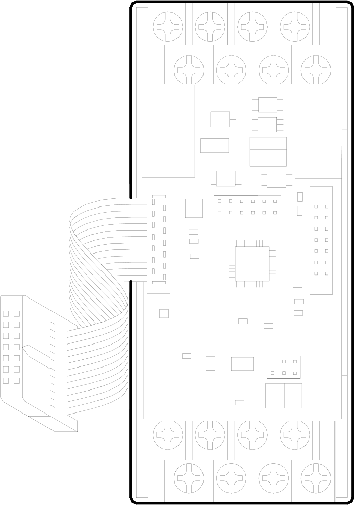
○1External power input terminal :Power supply of analogue circuit for this module, the voltage can be 24VDC±20%
and should be supplied with 4W of power at least.
○2Protecting ground terminal:Connect to the shielding of signal cable.
○3Expansion input cable:It should be connected to the front expansion unit, or the expansion output of main unit.
○4Expansion output connector:Provides the connection for next expansion unit.
○5Power indicator:It indicates whether the power supply at analogue circuit and external input power source are
normal.
○6AG Ground:No connection is needed in general; except when the common mode signal is too high. See examples
overleaf for details.
|
○7、○8:Output terminal of CH0~CH1. ○9、○12 :Input terminal of CH0~CH3. |
|
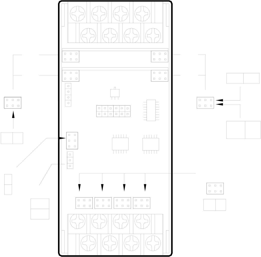
18.3.4.1 FBs-4A2D Hardware Jumper Setting |
|
CH0 |
CH0 |
|
V |
I |
B |
U |
U |
D/A |
V |
I |
CH1 |
CH1 |
B |
U |
|
10V |
5V |
||||||||||
|
JP1 |
B |
JPA |
JPB |
5V |
|||||||
|
10V |
|||||||||||
|
JP4 |
|||||||||||
|
JP3 |
JP5 ~ JP8 |
||||||||||
|
U |
|||||||||||
|
B |
|||||||||||
|
JP1 |
B |
U |
A/D |
I |
V |
||||||
|
5V |
|||||||||||
10V
Pin Layout in Control Board (open top cover)
● (Analog output)
1. Output code format selection (JP1)
Pin Layout on I/O Board (Remove Control Board)
Users can select between unipolar and bipolar codes. The output range of unipolar codes and bipolar codes is 0~16383 and –8192~8191, respectively. The two extreme values of these formats correspond to the lowest and highest output signal values, respectively (see table below). In general, the output code format is selected according to the form





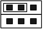




of output signals; i.e. unipolar codes for unipolar output signals; and bipolar codes for bipolar output signals. In doing so, their correlations will become more heuristics. Yet, as the format of output code on all channels is selected from JP1, it is the user’s choice to select unipolar or bipolar codes if both are used on different channels. See diagram above for location of JP1 :
|








2. Output signal form setup (JPA&JPB)
Users can set the output signal form (voltage/current) of individual channels; except the polarity and amplitude which are common.
|
Signal Form |
JPA (voltage/current) Setting |
JPB (polarity/amplitude) Setting |
0V~10V
-10V~10V
0V~5V
-5V~5V
0mA~20mA
|
-20mA~20mA |
V |
I |
0mA~10mA
-10mA~10mA
● (Analog input)
1. Input code format selection (JP1)
Users can select between unipolar and bipolar codes. The input range of unipolar codes and bipolar codes is 0~16383 and –8192~8191, respectively. The two extreme values of these formats correspond to the lowest and highest input signal values, respectively (see table below). For example, if the input signal type is set to -10V~ +10V, the unipolar code corresponding to the input is 8192 and the bipolar code corresponding to the input is 0 for 0V input. If the input is 10V, the unipolar code corresponding to the input is 16383 and the bipolar code corresponding to the input is 8191. In general, the input code format is selected according to the form of input signals; i.e. unipolar codes for unipolar input


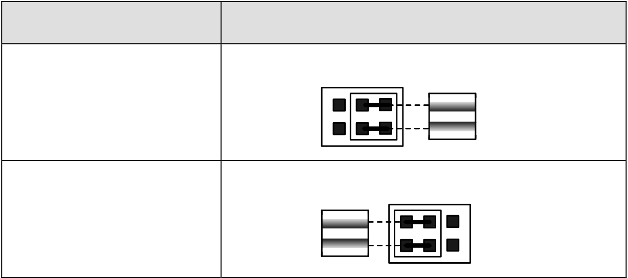
signals; and bipolar codes for bipolar input signals. In doing so, their correlations will become more heuristics. Unless it is
necessary to make a deviation conversion through FUN33; otherwise, do not select bipolar codes for unipolar input signals (see FUN33 description for details). The format of input codes of all channels is selected from JP1. See above diagram for the location of JP1:
|
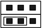

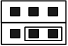







2. Input signal form setup (JP3&JP4)
Users can set the input signal form (voltage/current) of individual channels; except the polarity and amplitude which are common. The location of jumpers are tabulated below:
|
Signal Form |
JP3 Setting |
JP4Setting |
|||||||||||
|
0~10V |
|
|
|||||||||||
|
0~5V 0~10mA |
|
||||||||||||
|
-10~+10V |
|
|
|||||||||||
|
-5~+5V |
|

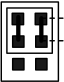
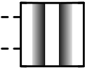


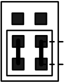
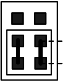



3. Voltage or current setting (JP5~JP8)
|
Signal Type |
JP5(CH0) ~ JP8(CH3) Setting |
Voltage
|
I |
V |
Current
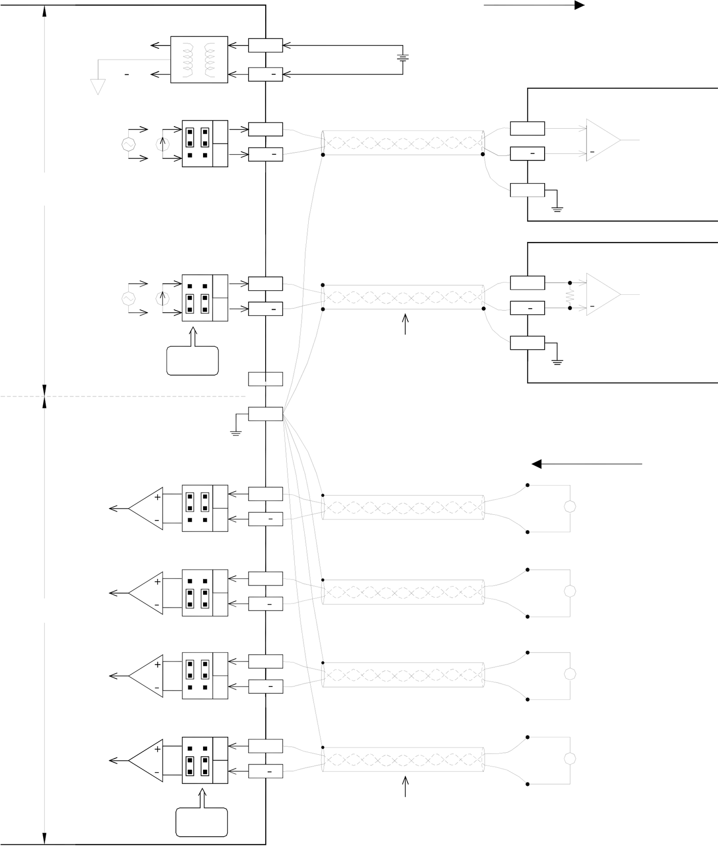
|
18.3.5 FBs-4A2D Input/Output Circuit Diagram |
|
FBs-4A2D |
V |
24V+ |
Output |
+ |
|
|
+15V |
+ |
24VDC |
|||
|
15V |
24V |
External power supply |
|||
|
O0+ |
CH0 Voltage output |
||||
|
V+ |
|||||
|
O0 |
V |
||||
|
I |
|||||
Voltage Input D/A FG
CH1 Current Input
|
V |
O1+ |
I+ |
+ |
|
O1 |
I |
||
|
I |
Current Input
|
Voltage/ |
Twisted pair with shielding |
FG |
Current output
|
selection |
AG |
FG
Input
|
A/D |
V |
I0+ |
Twisted pair with shielding |
V |
CH0 Input |
|
I |
I0 |
(Voltage source) |
|||
|
I1+ |
I |
CH1 Input |
|||
|
V |
|||||
|
I |
I1 |
(Current source) |
|||
|
I2+ |
V |
CH2 Input |
|||
|
V |
|||||
|
I |
I2 |
(Voltage source) |
|||
|
I3+ |
I |
CH3 Input |
|||
|
V |
|||||
|
I |
I3 |
(Current source) |
|||
|
Voltage/ |
Current input
selection
|
18.3.6 FBs-4A2D Input/Output Characteristics |
Users can select the I/O ranges of FBs-4A2D from the jumpers described above, such as V/I, U/B (I/O codes), U/B
(signal form), 5V/10V, etc. The I/O conversion characteristics of these settings are illustrated below. Users can adjust
different I/O forms by coordinating the conversion curve with various V/I (voltage/current) I/O settings. See Section 18.3.4
for details of V/I settings.
Tip: press ← → to switch chapters, Ctrl+K to search