7 Power Supply Wiring & Power Consumption Calculation and Power Sequencing Requirements
Power Supply Wiring & Power Consumption Calculation and Power Sequencing Requirements
There are two kinds of power for M series PLC power module. The 1st one is CPU dedicated power supply (To CPU & high speed or local I/O Expansion modules). The 2nd one is external Sensor power supply. The CPU module and the expansion module are also divided in 2 parts of circuits. The 1st one is 24VDC (Internal Circuit), the 2nd one is 24VDC (Output Sensor Circuit). The 24VDC (Internal Circuit) is supplied by the CPU dedicated power supply of the M series PLC power module. The 24VDC (Output Sensor Circuit) can be supplied by an external power supply or by the external Sensor power supply of the M series PLC power module. Neither the CPU module nor the expansion module has internal power supply, and both must consume the power of the power module to supply power.
|
⚠Caution |
|
In industrial environments, main power may irregularly experience a surge current or high voltage pulse caused by the start or shut down of high power equipment. Users are advised to take necessary measures (for example, the use of isolation transformer or other MOV suppression devices) for the protection of PLC and its peripherals. |
|
⚠Caution |
|
Dans les environnements industriels, l’alimentation principale peut subir de manière irrégulière des surtensions de courant ou des impulsions de haute tension, provoquées par la mise en marche ou l’arrêt d’équipements de forte puissance. Il est recommandé aux utilisateurs de prendre les mesures nécessaires (par exemple l’utilisation d’un transformateur d’isolement ou d’autres dispositifs de suppression tels que les varistances MOV) afin de protéger le PLC et ses périphériques. |
7-1 Specifications and Wiring of Power Module
Power Module Specification Table
|
Specification Model |
MPA024-24 |
MPA048-24 |
MRPWE-AC |
|
|
input |
Input Voltage |
100~240VAC |
100~240VAC |
100~240VAC |
|
Input Frequency |
50/60Hz |
50/60Hz |
50/60Hz |
|
|
Max. Input Current |
1A max. |
1A max. |
1A max. |
|
|
Inrush Current (Cold Start) |
22A/115Vac (44A/230Vac) |
22A/115Vac (44A/230Vac) |
22A/115Vac (44A/230Vac) |
|
|
Withstand voltage |
3,000 VAC (Primary-secondary), 1,500 VAC (Primary-PE), 500 VAC(Secondary-PE) |
3,000 VAC (Primary-secondary), 1,500 VAC (Primary-PE), 500 VAC(Secondary-PE) |
3,000 VAC (Primary-secondary), 1,500 VAC (Primary-PE), 500 VAC(Secondary-PE) |
|
|
Insulation resistance |
>100MΩ/500VDC |
>100MΩ/500VDC |
>100MΩ/500VDC |
|
|
Fuse Spec. |
2A |
2A |
2A |
|
|
Hold-up time |
>15ms/ 115VAC, >60ms/ 220VAC |
>15ms/ 115VAC, >60ms/ 220VAC |
>15ms/ 115VAC, >60ms/ 220VAC |
|
|
Isolation Type |
Transformer/ Photocoupler Isolation,1500VAC/1 minute |
Transformer/ Photocoupler Isolation,1500VAC/1 minute |
Transformer/ Photocoupler Isolation,1500VAC/1 minute |
|
|
Operation indication |
LED (green) |
LED (green) |
LED (green) |
|
|
output |
Rated output power |
24W (Shared CPU dedicated power supply and external Sensor power supply) |
48W (Shared CPU dedicated power supply and external Sensor power supply) |
48W (Shared CPU dedicated power supply and external Sensor power supply) |
|
Rated output current |
1A (Shared CPU dedicated power supply and external Sensor power supply) |
2A (Shared CPU dedicated power supply and external Sensor power supply) |
2A (Shared CPU dedicated power supply and external Sensor power supply) |
|
|
Output voltage range |
24VDC±1% |
24VDC±1% |
24VDC±1% |
|
|
Conversion efficiency |
86%/110VAC,87%/220VAC |
86%/110VAC,87%/220VAC |
86%/110VAC,87%/220VAC |
|
|
Protection |
Overvoltage protection |
Latching overvoltage protection, re-power on to recover 34V~36V |
Latching overvoltage protection, re-power on to recover 34V~36V |
Latching overvoltage protection, re-power on to recover 34V~36V |
|
Overcurrent protection |
Method: Foldback overload protection, automatically recover when overload is removed 101%~133% rated output power |
Method: Foldback overload protection, automatically recover when overload is removed 101%~133% rated output power |
Method: Foldback overload protection, automatically recover when overload is removed 101%~133% rated output power |
|
|
Environmental Specifications |
Operating Ambient Temperature |
0℃~55℃ |
0℃~55℃ |
0℃~55℃ |
|
Relative Humidity |
20 ~ 90% (non-condensing) |
20 ~ 90% (non-condensing) |
20 ~ 90% (non-condensing) |
|
|
Storage Temperature |
-25 ~ +70℃ |
-25 ~ +70℃ |
-25 ~ +70℃ |
|
|
Certifications |
CE |
CE |
CE |
|
|
External dimensions |
90mmX33.7mmX90mm |
90mmX33.7mmX90mm |
90mmX46.2mmX90mm |
|
|
⚠Caution |
|
The schematic diagram of power module is shown below. Also be cautious about the following:
|
|
⚠Caution |
|
Le schéma de principe du module de puissance est illustré ci-dessous. Il convient également de faire attention aux points suivants :
|
|
⚠Warning |
|
24VDC Output power for Sensor circuit cannot be connected in parallel with other powers, in which the conflict between two sets of power will decrease their lifetime or cause immediate damage. This will induce unexpected malfunction of PLC and cause serious or even deadly damage to people or equipment. |
|
⚠ Avertissement |
|
L’alimentation de sortie 24VDC pour le circuit du capteur ne peut pas être connectée en parallèle avec d’autres alimentations, dans lesquelles le conflit entre deux ensembles d’alimentation réduira leur durée de vie ou causera des dommages immédiats. Cela entraînerait un dysfonctionnement inattendu de l’automate et causerait des dommages graves, voire mortels, aux personnes ou à l’équipement. |
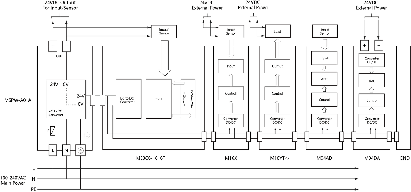
PLC System Wiring
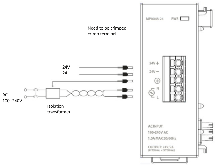
Power Supply Wiring Diagram
7-2 Maximum Current Consumption of Expansion Module
The CPU module and expansion modules themselves have no power supply and must be supplied by the M series PLC power module. The following table shows the maximum current consumption of each expansion module.
|
⚠Warning |
|
Any output of M series PLC power module, the total amount of current cannot exceed the value listed in the below table. Any violation will cause a voltage drop by overloading the power supply, or intermittent powered with the supply in protection mode, either of which will result in unexpected action of PLC and cause harm to people or damage to equipment. |
|
⚠ Avertissement |
|
Pour toute sortie d’un module d’alimentation PLC de la série M, la quantité totale de courant ne peut pas dépasser la valeur indiquée dans le tableau ci-dessous. Toute violation entraînera une chute de tension en surchargeant l’alimentation, ou une alimentation intermittente avec l’alimentation en mode de protection, ce qui entraînera une action inattendue de l’automate et causera des dommages aux personnes ou à l’équipement. |
Maximum Current Consumption of Expansion Module Table
|
Model Current Consumption |
24VDC (Internal Circuit) |
24VDC (Output Sensor Circuit) |
||
|
Advanced and power Expansion Modules |
Power Modules |
MPA024-24 |
– |
– |
|
MPA048-24 |
– |
– |
||
|
Plug-in Expansion Boards |
Communication Plug-in Expansion Boards |
MB-CB2 |
Approaches 0 mA |
|
|
MB-CB5 |
Approaches 0 mA |
|||
|
DI Plug-in Expansion Boards |
MB-2HSC |
Approaches 0 mA |
||
|
MB-4X |
Approaches 0 mA |
|||
|
DO Plug-in Expansion Boards |
MB-2PSO◇ |
Approaches 0 mA |
||
|
MB-4Y◇ |
Approaches 0 mA |
|||
|
AI Plug-in Expansion Boards |
MB-2ADL |
20 mA |
||
|
AO Plug-in Expansion Boards |
MB-2DAL |
80 mA |
||
|
RTC Plug-in Expansion Boards |
MB-RTC |
Approaches 0 mA |
||
|
High Speed Expansion Modules |
High Speed Communication Modules |
MHCM22 |
40mA |
|
|
MHCM55 |
40mA |
|||
|
MHCM25 |
40mA |
|||
|
Local I/O Expansion Modules |
DI Modules |
M16X |
70mA |
7.5mA/ Point |
|
DO Modules |
M16YT |
150mA |
Max.0.5A/ Point |
|
|
M16YJ |
163mA |
Max.0.5A/ Point |
||
|
M16YR |
90mA |
Max.2A/ Point |
||
|
DIO Combo Modules |
M1616XYT |
202mA |
X :7.5mA |
|
|
M1616XYJ |
202mA |
X :7.5mA |
||
|
M1616XYR |
202mA |
X :7.5mA Y:@2A/Point |
||
|
AI Modules |
M04AD |
78.2mA |
– |
|
|
M04ADR |
78.2mA |
– |
||
|
AO Modules |
M04DA |
14.2mA |
107mA |
|
|
M04DAR |
14.2mA |
107mA |
||
|
AIO Combo Modules |
M0202AH |
22.58mA |
39.85mA |
|
|
Temperature measurement Modules |
M04TC |
30.7mA |
– |
|
|
M04TCR |
30.7mA |
– |
||
|
Temperature Measurement Combo Modules |
M0202TH |
30mA |
– |
|
|
Load Cell Modules |
M02LC |
40.64mA |
– |
|
|
M02LCR |
56.1mA |
– |
||
|
End module |
MRE |
– |
– |
|
|
I/O Bus Extension modules |
Repeater Modules |
MRPWE-AC |
– |
– |
|
I/O Bus Extension module(Head) |
MRGH |
– |
– |
|
|
I/O Bus Extension module(Tail) |
MRGT |
– |
– |
|
|
Remote Expansion Modules |
Remote I/O Coupler |
MC0EN |
80mA |
– |
Maximum Current Consumption of CPU Module Table
|
Model Current |
24VDC (Internal Circuit) |
24VDC (Output Sensor Circuit) |
||
|
CPU Modules |
Compact CPU Modules |
MQ2M0-1616◇ |
150mA |
DI : 7.5mA/Point DO : Max.0.1A/Point |
|
MQ2M1-1616◇ |
150mA |
DI : 7.5mA/Point DO : Max.0.1A/Point |
||
|
MQ2M3-1616◇ |
150mA |
DI : 7.5mA/Point DO : Max.0.1A/Point |
||
|
MQ2M6-1616◇ |
150mA |
DI : 7.5mA/Point DO : Max.0.1A/Point |
||
|
Advanced CPU Modules |
MA1N0-1616◇ |
150mA |
DI : 7.5mA/Point DO : Max.0.1A/Point |
|
|
MA1N3-1616◇ |
150mA |
DI : 7.5mA/Point DO : Max.0.1A/Point |
||
|
MA1I4-1616◇ |
150mA |
DI : 7.5mA/Point DO : Max.0.1A/Point |
||
|
General Motion Control CPU Module |
MS2C4-1616◇ |
200mA |
DI : 7.5mA/Point DO : Max.0.1A/Point |
|
|
MS2C5-1616◇ |
200mA |
DI : 7.5mA/Point DO : Max.0.1A/Point |
||
|
MS3C6-1616◇ |
200mA |
DI : 7.5mA/Point DO : Max.0.1A/Point |
||
|
MU2C4-1616◇ |
200mA |
DI : 7.5mA/Point DO : Max.0.1A/Point |
||
|
MU2C6-1616◇ |
200mA |
DI : 7.5mA/Point DO : Max.0.1A/Point |
||
|
MU3C2-1616◇ |
200mA |
DI : 7.5mA/Point DO : Max.0.1A/Point |
||
|
MU3C3-1616◇ |
200mA |
DI : 7.5mA/Point DO : Max.0.1A/Point |
||
|
MU3C4-1616◇ |
200mA |
DI : 7.5mA/Point DO : Max.0.1A/Point |
||
|
MU3C5-1616◇ |
200mA |
DI : 7.5mA/Point DO : Max.0.1A/Point |
||
|
MU3C6-1616◇ |
200mA |
DI : 7.5mA/Point DO : Max.0.1A/Point |
||
|
Advanced Motion Control CPU Module |
ME2C3-1616◇ |
200mA |
DI : 7.5mA/Point DO : Max.0.1A/Point |
|
|
ME2C4-1616◇ |
200mA |
DI : 7.5mA/Point DO : Max.0.1A/Point |
||
|
ME2C5-1616◇ |
200mA |
DI : 7.5mA/Point DO : Max.0.1A/Point |
||
|
ME3C6-1616◇ |
200mA |
DI : 7.5mA/Point DO : Max.0.1A/Point |
||
7-3 Calculation Example of Power Capacity
Power module selection is depending on the sum of current consumption of all modules. Therefore, user must know the current consumption of each module. Please refer to the maximum current consumption of expansion module table, which has the maximum current consumption of each expansion module.
User must consider the match between power and expansion modules cannot cause output power of any one group of overload use.
The below diagram is a System Modules, try to calculate the power supply used of the system.
|
Type |
Power Module |
CPU Module |
Expansion Module |
Expansion Module |
Expansion Module |
Expansion Module |
END Module |
Extra Capacity |
|
Module Name |
MPA024- 24 |
ME3C6- 1616T |
M16XX |
M16YT |
M04AD |
M04TC |
MRE |
|
|
24VDC (Input Circuit) |
+1000mA |
-200mA |
-70mA |
-150mA |
-78.2mA |
-30.7mA |
– |
231.1mA |
|
24VDC (Output Circuit) |
-7.5mA*16 Point |
-7.5mA*16 Point |
– |
– |
– |
– |
- Power Module – 24VDC (Input Circuit) – 24VDC (Output Circuit)
【1000mA】–【200mA+70mA+150mA+78.2mA+30.7mA】-【(7.5mA*16)+(7.5mA*16)】=231.1mA
7-4 Requirement of Power Sequence in CPU Modlue & Expansion Module
When the power is on, the M Series PLC first detects the type and number of expansion module attached to its expansion interface and get the actual I/O configuration. Therefore, while the CPU module performs detection, the power in expansion module should be already UP, otherwise, the detected I/O configuration will not correct. Namely, the power of expansion module should be ON simultaneously or even earlier. There will be no time sequence error when CPU module/expansion module are connected together to one power. If the expansion module and CPU module powered by different powers (or the same power but different switches), or external power supply is used for expansion modules, time sequence of both powers should be considered. To solve the problem of the expansion module power not get ready before CPU module power does, M Series PLC provides a special R35367 register which can delay the detection time of I/O configuration. The time base of R35367 is 0.01sec with a default value of 0, which can be set from 0~1000 (1~10c), as shown in the figure below. If the expansion module power cannot be UP within 1sec after main unit power is ON, the R35367 time needs to be set longer to delay the detection by CPU. It cannot exceed 10sec, however, otherwise the configuration of expansion interface cannot be detected.
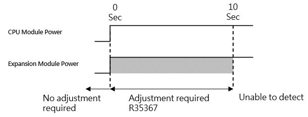
Power Timing Diagram
Tip: press ← → to switch chapters, Ctrl+K to search