8-1 Communication Plug-in Expansion Boards Specifications
If the communication Port of the M Series CPU module is not enough for a specific application, then can expand it with the additional plug-in Expansion Boards.
8-1-1 MB-CB2 Specifications
Appearance and Function
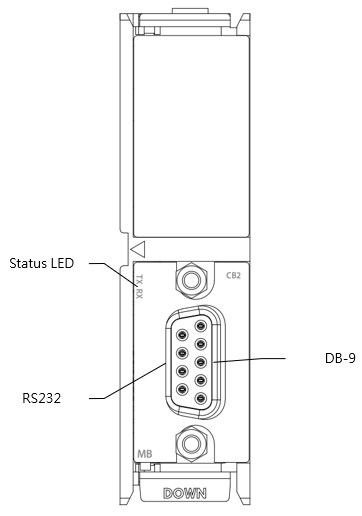
MB-CB2 Appearance
Technical Specifications
MB-CB2 Technical Specifications Table
|
Item |
Technical Specifications |
|
Model |
MB-CB2 |
|
connection interface |
1 Port RS232 |
|
Maximum number of connections |
1 Slave |
|
Connector type |
D-Sub 9-Pins |
|
Transmission rate |
Max 115200 |
|
Maximum cable length |
15M* |
* It varies based on cable material, communication speed and usage environment.
Status Indicator
MB-CB2 Status Indicator Table
|
Name |
instruction |
|
RX Port Indicator |
Port is receiving: yellow-green light |
|
TX Port Indicator |
Port is transmitting: orange light |
Pin assignment of the connector
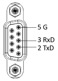
MB-CB2 Pins
8-1-2 MB-CB5 Specifications
Appearance and Function
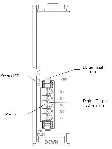
MB-CB5 Appearance
Technical Specifications
MB-CB5 Technical Specifications Table
|
Item |
Technical Specifications |
|
Model |
MB-CB5 |
|
connection interface |
1 Port RS485 |
|
Maximum number of connections |
32 Slaves |
|
Connector type |
5 pins spring terminal |
|
Transmission rate |
Max 230400 |
|
Maximum cable length |
1200M* |
* It varies based on cable material, communication speed and usage environment.
Status Indicator
MB-CB5 Status Indicator Table
|
Name |
instruction |
|
RX Port Indicator |
Port is receiving: yellow-green light |
|
TX Port Indicator |
Port is transmitting: orange light |
Pin assignment of the connector
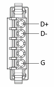
MB-CB5 Pins
8-1-3 MB-CBEQ Specifications
Appearance and Function
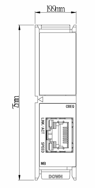
MB-CBEQ Specifications
Technical Specifications
MB-CB5 Technical Specifications Table
|
Item |
Technical Specifications |
|
Model |
MB-CBEQ |
|
Network interface |
10/100Base T |
|
Internet Protocol |
TCP/IP |
* It varies based on cable material, communication speed and usage environment.
8-2 High Speed Digital Input Plug-in Expansion Boards Specifications
If the input point of the M Series CPU module is not enough for a specific application, then can expand it with the additional plug-in expansion boards.
8-2-1 MB-2HSC Specifications
Appearance and Function
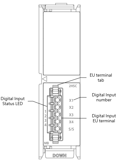
MB-2HSC Appearance
Technical Specifications
MB-2HSC Technical Specifications Table
|
Item |
Technical Specifications |
|
|
Model |
MB-2HSC |
|
|
Input Points |
4 |
|
|
Input Points Type |
24VDC Single-end input |
|
|
Maximum input frequency |
High Speed Counter,200kHz |
|
|
Input Signal Voltage |
24VDC±10% |
|
|
Input Current Threshold |
ON Current |
>4mA |
|
OFF Current |
<2mA |
|
|
Maximum Input Current |
6mA |
|
|
Input Resistance |
3.3kΩ |
|
|
Isolation Type |
Transformer/ Photocoupler Isolation,1500VAC/1 minute |
|
|
SINK /SOURCE Wiring |
Via variation of internal common terminal S/S and external common wiring |
|
|
Noise Filtering Time Constant |
DHF(0 ~ 15ms)+AHF(0.47μs) |
|
Status Indicator
MB-2HSC Status Indicator Table
|
Indicator |
instruction |
|
1~4 Input Indicator |
ON: green light OFF: no light |
Wiring
- Wiring of single-end common SINK input
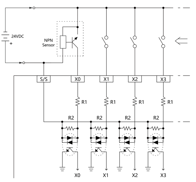
Wiring of single-end common SINK input
- Wiring of single-end common SOURCE input
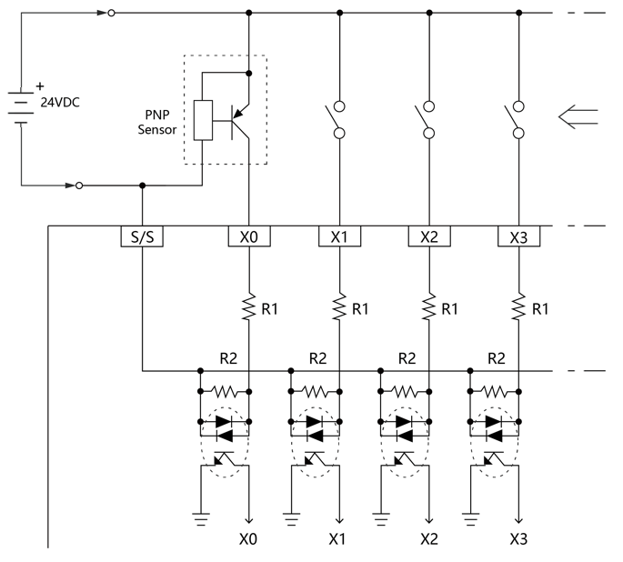
Wiring of single-end common SOURCE input
8-2-2 MB-4X Specifications
If the input point of the M Series CPU module is not enough for a specific application, then can expand it with the additional plug-in expansion boards.
Appearance and Function
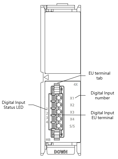
MB-4X Appearance
Technical Specifications
MB-4X Technical Specifications Table
|
Item |
Technical Specifications |
|
|
Model |
MB-4X |
|
|
Input Points |
4 |
|
|
Input Points Type |
24VDC Single-end input |
|
|
Maximum input frequency |
1kHz |
|
|
Input Signal Voltage |
24VDC±10% |
|
|
Input Current Threshold |
ON Current |
>4mA |
|
OFF Current |
<2mA |
|
|
Maximum Input Current |
6mA |
|
|
Input Resistance |
5.6kΩ |
|
|
Isolation Type |
Transformer/ Photocoupler Isolation,1500VAC/1 minute |
|
|
SINK /SOURCE Wiring |
Via variation of internal common terminal S/S and external common wiring |
|
|
Noise Filtering Time Constant |
DHF(0 ~ 70ms)+AHF(0.47μs) |
|
Status Indicator
MB-4X Status Indicator Table
|
Indicator |
instruction |
|
1~4 Input Indicator |
ON: green light OFF: no light |
Wiring
- Wiring of single-end common SINK input
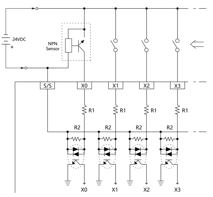
Wiring of single-end common SINK input
- Wiring of single-end common SOURCE input
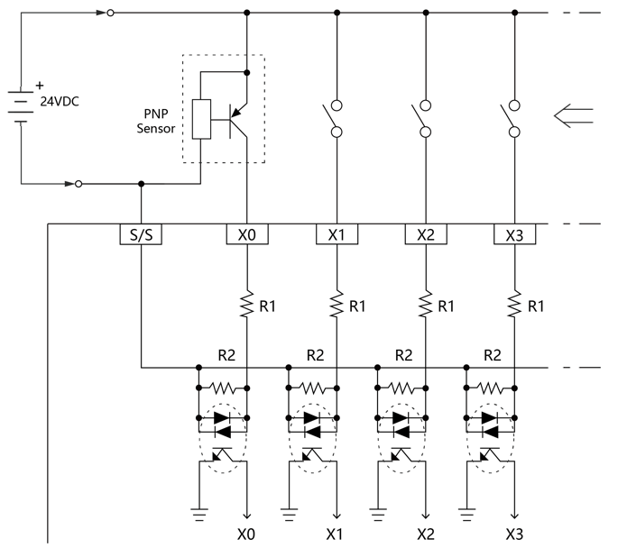
Wiring of single-end common SOURCE input
8-3 High Speed Digital output Plug-in Expansion Boards Specifications
If the output point of the M Series CPU module is not enough for a specific application, then can expand it with the additional plug-in Expansion Boards.
8-3-1 MB-2PSOT/MB-2PSOJ Specifications
Appearance and Function
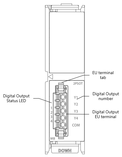
MB-2PSOT Appearance
Technical Specifications
MB-2PSOT/MB-2PSOJ Technical Specifications Table
|
Item |
Technical Specifications |
|
|
model |
MB-2PSOT/MB-2PSOJ |
|
|
Output Points |
4 |
|
|
Output Points Type |
Single-End Transistor Output; T-Transistor SINK(NPN) output; J-Transistor SOURCE(PNP) output |
|
|
Maximum output frequency |
High Speed Pulses Output,200kHz |
|
|
Working Voltage |
5~30VDC |
|
|
Maximum Load Current |
Resistive |
0.1A/Single 0.4A/COM |
|
Inductive |
||
|
Maximum Voltage Drop/conducing resistance |
0.6V |
|
|
Minimum Load |
– |
|
|
Leakage Current |
<0.1mA/30VDC |
|
|
Maximum Output Delay Time |
ON > OFF |
<2μS |
|
OFF > ON |
<2μS |
|
|
Over Current Protection |
N/A |
|
|
Isolation Type |
Photocoupler Isolation, 500VAC, 1 minute |
|
|
SINK /SOURCE Type |
Choose SINK/SOURCE by models and non-exchangeable |
|
Status Indicator
MB-2PSOT/MB-2PSOJ Status Indicator Table
|
Indicator |
instruction |
|
1~4 Output Indicator |
ON: green light OFF: no light |
Wiring
- Transistor Single-End SINK Output
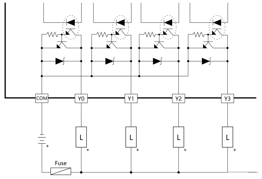
Transistor Single-End SINK Output
- Transistor Single-End SOURCE Output
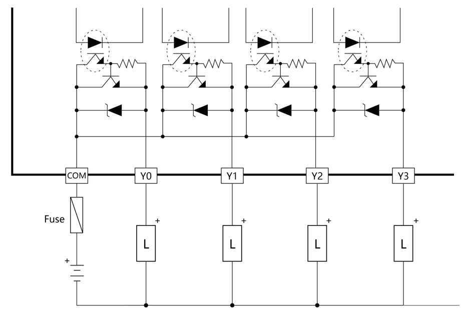
Transistor Single-End SOURCE Output
8-3-2 MB-4YT/MB-4YJ Specifications
Appearance and Function
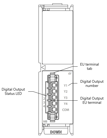
MB-4YT/MB-4YJ Appearance
Technical Specifications
MB-4YT/MB-4YJ Technical Specifications Table
|
Item |
Technical Specifications |
|
|
model |
MB-4YT/MB-4YJ |
|
|
Output Points |
4 |
|
|
Output Points Type |
Single-End Transistor Output; T-Transistor SINK(NPN) output; J-Transistor SOURCE(PNP) output |
|
|
Maximum output frequency |
1kHz |
|
|
Working Voltage |
5~30VDC |
|
|
Maximum Load Current |
Resistive |
0.1A/Single 0.4A/COM |
|
Inductive |
||
|
Maximum Voltage Drop/conducing resistance |
0.6V |
|
|
Minimum Load |
– |
|
|
Leakage Current |
<0.1mA/30VDC |
|
|
Maximum Output Delay Time |
ON > OFF |
<2μS |
|
OFF > ON |
<2μS |
|
|
Over Current Protection |
N/A |
|
|
Isolation Type |
Photocoupler Isolation, 500VAC, 1 minute |
|
|
SINK /SOURCE Type |
Choose SINK/SOURCE by models and non-exchangeable |
|
Status Indicator
MB-4YT/MB-4YJ Status Indicator Table
|
Indicator |
instruction |
|
1~4 Output Indicator |
ON: green light OFF: no light |
Wiring
- Transistor Single-End SINK Output
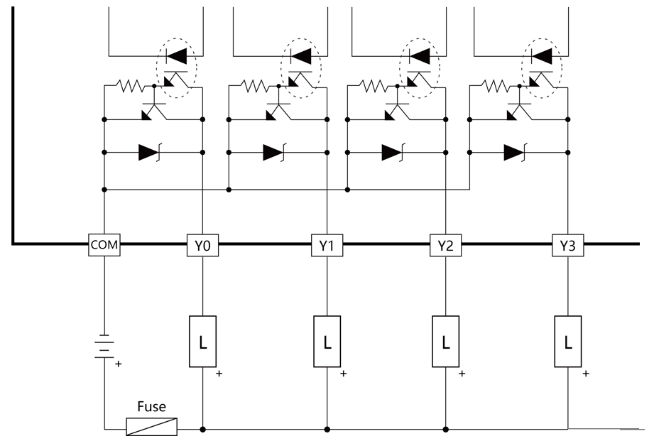
Transistor Single-End SINK Output
- Transistor Single-End SOURCE Output
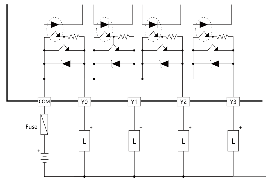
Transistor Single-End SOURCE Output
8-4 Analog Input Plug-in Expansion Boards Specifications
If the output point of the M Series CPU module is not enough for a specific application, then can expand it with the additional plug-in Expansion Boards.
8-4-1 MB-2ADL Specification
Appearance and Function
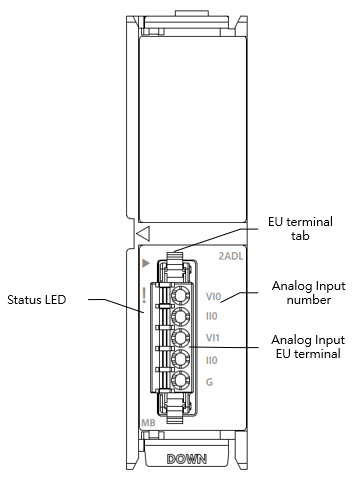
MB-2ADL Appearance
Technical Specification
MB-2ADL Technical Specification Table
|
Item |
Technical Specification |
|||
|
Model |
MB-2ADL |
|||
|
Input Point |
2 |
|||
|
Conversion speed |
PLC Scan Time |
|||
|
Analog Input Characteristics and Resolution |
Analog input range |
Data |
Resolution |
|
|
Voltage |
0~10V |
0~ 4095 |
2.44mV |
|
|
Current |
0~20mA |
0~ 4095 |
4.88μA |
|
|
Conversion precision |
Voltage |
±1% (25°C±5℃) |
||
|
Current |
±1% (25°C±5℃) |
|||
|
AD Converter |
12-Bit |
|||
|
Input Resistance |
Voltage:100KΩ Current:125Ω |
|||
|
Hardware maximum input |
Voltage:-15V~+15V Current:-30mA~+30mA |
|||
|
Insulation |
None |
|||
Status Indicator
MB-2ADL Status Indicator Table
|
Indicator |
instruction |
|
ACT Indicator |
Running: green light |
|
ERR Indicator |
In ERROR: red light |
Wiring
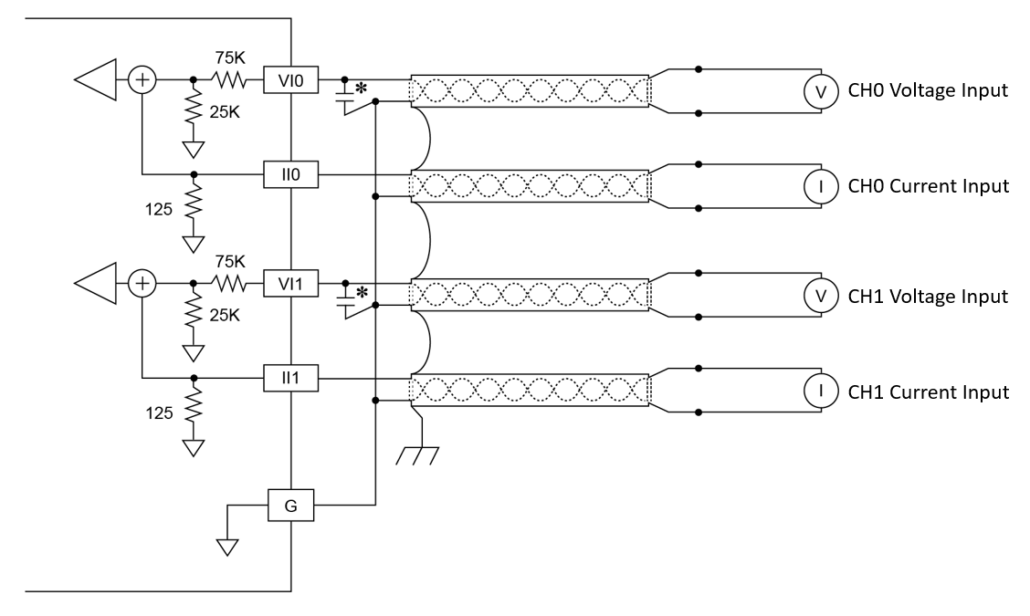
0.1~0.47 μF capacitor (for noise filtering) is recommended, though not mandatory.
MB-2ADL Wiring
8-5 Analog Output Plug-in Expansion Boards Specifications
If the output point of the M Series CPU module is not enough for a specific application, then can expand it with the additional plug-in Expansion Boards.
8-5-1 MB-2DAL Specification
Appearance and Function
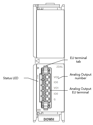
MB-2DAL Appearance
Technical Specification
MB-2DAL Technical Specification
|
Item |
Technical Specification |
|||
|
model |
MB-2DAL |
|||
|
Output Point |
2 |
|||
|
Conversion speed |
PLC Scan Time |
|||
|
Analog output characteristics and resolution |
Analog output range |
Data |
Resolution |
|
|
Voltage |
0~10V |
0~4095 |
2.44mV |
|
|
0~5V |
0~4095 |
1.22mV |
||
|
Current |
0~20mA |
0~4095 |
4.88μA |
|
|
0~10mA |
0~4095 |
2.44μA |
||
|
Conversion precision |
Voltage |
±0.1% (25℃±5℃) |
||
|
Current |
±0.1% (25℃±5℃) |
|||
|
DA Converter |
12-Bit |
|||
|
Minimum load impedance |
Voltage:500~1MΩ |
|||
|
Maximum load impedance |
Current:0~500Ω |
|||
|
Insulation |
None |
|||
Status Indicator
MB-2DAL Status Indicator Table
|
Indicator |
instruction |
|
ACT Indicator |
Running: green light |
|
ERR Indicator |
In ERROR: red light |
Wiring
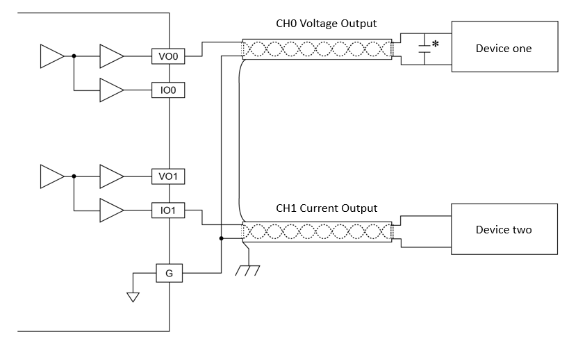
0.1~0.47 μF capacitor (for noise filtering) is recommended, though not mandatory.
MB-2DAL Wiring
8-6 RTC Plug-in Expansion Boards Specifications
If the MQ series CPU module requires RTC function, then can expand it with the RTC plug-in expansion boards.
8-6-1 MB-RTC Specifications
Appearance and Function
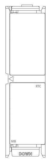
MB-RTC Appearance
Technical Specifications
MB-RTC Technical Specifications Table
|
Item |
Technical Specifications |
|
Model |
MB-RTC |
|
Function |
Real Time Clock The RTC can keep time correctly regardless of whether the PLC is powered on or off. Provides 7 types of time including week, year, month, day, hour, minute, second…etc. |
|
battery model |
CR2450 size non-charge battery |
|
Battery Life |
10 years* |
* It varies based on usage, environment, temperature or other conditions.
Tip: press ← → to switch chapters, Ctrl+K to search