M-Series PLC supports FATEK Memory Card, and the supported features may vary among series. The memory card and description are shown below:
|
Item |
MFM06 |
|
System |
FAT32 |
|
Function |
Firmware update System Backup and Restoration (Register/Program/System Data) Memory Card Register Read/Write Protection of Copy |
Firmware Update
Multiple expansion modules and CPU Unit firmware can be updated to easily complete system upgrades.
System Backup and Restoration (Register/Program/System Data)
Users can quickly copy the program during mass production through the memory card. After the designer completes the first machine tool, subsequent machines can use this function to quickly complete a large number of copy shipments.
Memory Card Register Read/Write
During the execution of the Ladder program, the user backs up the register data through the special command WR-MP (161), or writes the backup data to a specific register address through the special command RD-MP (162).
Protection of Copy
One-to-one binding between the memory card and the CPU Unit provides a protection method for the user to misuse the memory card. If you want to unbind, you need to execute the unbind action on the original CPU Unit.
7-1 Writing Backup Information
The execution time of backing up information is when the CPU Unit is powered on, and the restriction is that it must be in STOP mode. Therefore, if the memory card written into the system backup is to be backed up on a CPU Unit computer, it must be inserted into the slot before power-on, and the DIP switch must be switched to STOP mode before power-on. Subsequent CPU Units will perform restoration operations according to the backup content of the memory card.
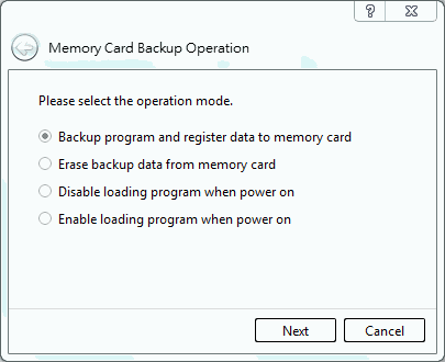
Figure 21 Writing Backup Information
7-1-1 Writing Backup Information through Software
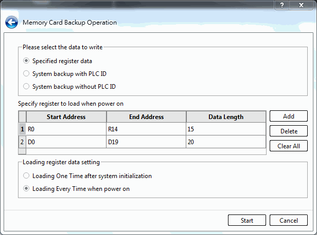
Figure 22 Replicating Program and Register to Memory Card
- Data_Data Register to be replicated
With such option, you may replicate the program and register content to the memory card. After selecting “Add”, the system will display the data register picture showing the register that has been appointed for replicating to the memory card. On such planning page, you may define the scope of register that will be read back from the memory card when turning on the PLC. If not required, you may back up the data register on the memory card and then press “Start” to start the replicating process.
※ The PLC allows you to replicate max. 4 lots of data registers to the memory card. You may execute the addition or deduction by clicking “Add” or “Delete”.
※ Upon each start, the memory card will display the data register being replicated on the memory card such as the machine adjustment value or the constant application value. As a result, you may use the initial value of the data register corresponding to the RAM of the CPU module as the value being written to the memory card in order that correct operating data will be saved permanently and that the maintenance will be executed more easily.
※ To copy the content of all registers to the memory card, simply click “System backup” without the need of executing the addition item by item.
- Replicated Data_System Backup (including PLC ID)
If it is required to include the PLC ID in the selected system backup copy, the PLC ID and the program will be loaded by the Memory Card upon each start. Depending on the options to be replicated, the Memory Card will upload all of the register data and the contact status that will be replicated per time (selecting “Upload for each start”) or once (selecting “Upload once when initialized”). In other words, the Memory Card created by such mode can be used to replicate massive amounts of data and upload the required ID (i.e. Program ID and PLC ID) to serve as the operation protecting control program in the PLC CPU Unit without the need of setting the ID through the program editing tool. When using Program ID and PLC ID as the operation protecting control program, do not install the Memory Card created by such mode on the PLC CPU Unit; otherwise, the protection purpose will never be achieved.
- Replicated Data_System Backup (excluding PLC ID):
If it is not required to include the PLC ID in the selected system backup copy, the Memory Card created by such mode will not include the replicated PLC ID. In this case, the Memory Card will upload the program upon each start. Depending on the options to be replicated, the Memory Card will upload all of the data, the register and the contact status that should be replicated per time (selecting “Upload for each start”) or once (selecting “Upload once when initialized”). When installing the Memory Card being set with Program ID for operation protecting on another PLC, the PLC ID of such PLC must be the same as the Program ID used by Memory Card so that such PLC will operate normally.
For the system that needs the Program ID and PLC ID to achieve the operation protection, such method can be used for replicating the ID to the Memory Card in order to realize mass production and long-term maintenance purposes.
7-1-2 Manual Backup Production
In order to meet the application requirements of different customers, the replication of the Memory Card can also be completed by setting the content value of the special register. The UperLogic users can skip this part because the setting is completed when the UperLogic performs the Memory Card operation option.
Related Register of Replicating Memory Card:
● R35480: Test-run modification mode or replicate the Memory Card command and status:
|
Register |
Setting |
Description of Function |
|
R35480 |
5530H (Test-run Modification Mode) |
If the Memory Card has been programmed with a Ladder program, the Ladder program stored in the RAM of the CPU module will not be overwritten by the Ladder program of the Memory Card every time it is turned on; that is, the Ladder program of the RAM of the CPU module will remain at the last modification state (when the PLC is running or being modified, it actually executes the Ladder program in the RAM of the CPU module). After the machine is in operation, if you need to modify the program, you can use this function; after all the modification and testing are completed, replicate the Ladder program and data register to the Memory Card. In case you want to give up during the program modification process and want to restore the original state, you only need to clear R35480 to 0 and restart the computer. |
|
Other Value |
If the Memory Card has been programmed with a Ladder program, the Ladder program on the Memory Card will overwrite the Ladder program stored in the RAM of the CPU module each time the machine is turned on, and the PLC will automatically enter the RUN mode. If a Memory Card is installed in the CPU module, after each test is completed, it is best to replicate the Ladder program and data register to the Memory Card for long-term storage and convenient maintenance. |
Table 10 Function of memory card-related register_R35480
● R35479 : Reading selection of the data register written in the Memory Card; when programming the Ladder program to the Memory Card, if there is also a plan to burn the data register (part or all) at the same time, each time the computer is turned on, The content of the data register that has been replicated to the Memory Card will be initialized to the value at the time of burning; this application will replicate the tuning parameters (stored in the data register) to the Memory Card after the test is completed. Mass production or maintenance would be of great help. However, there are many applications that only need to initialize the data register programmed into the Memory Card at the first boot, and the data register must maintain the value before shutdown when booting up later. The user can control the value of the data register R4046 to achieve the above two applications, the description is as follows:
|
Register |
Setting |
Description of Function |
|
R35479 |
5530H |
The data registers replicated to the Memory Card will not be initialized at startup, that is, the data registers will retain the value before shutdown. |
|
Other Value |
Every time the computer is turned on, the contents of the data registers programmed into the Memory Card will be initialized to the values at the time of replicating. |
Table 11 Function of memory card-related register_R35479
※ If you only need to initialize the data registers programmed into the Memory Card at the first boot, you only need to write the value of R35479 into 5530H in the Ladder program.
● In RUN/STOP mode, the PLC can issue the command to clear the Memory Card or replicate the Ladder + Register command:
|
Register |
Setting |
Description of Function |
|
R35480 |
5550H |
Issue the Clear Memory Card Command |
|
5551H |
Clearing |
|
|
5552H |
Clear Comparison |
|
|
5553H |
Clear Completed |
|
|
5554H |
Clear Failed |
|
|
5560H |
Issue the Command to Replicate Ladder + Register |
|
|
5562H |
Replicating Ladder Program |
|
|
5563H |
Replicating Register |
|
|
5566H |
Comparing the Replicated Ladder Program |
|
|
5567H |
Comparing the Replicated Register |
|
|
556AH |
Ladder + Register Replication Completed |
|
|
556BH |
Ladder Program Replication Error |
|
|
556CH |
Register Replication Error |
Table 12 Function of memory card-related register_R35480_2
7-1-3 Clearing Memory Card Data
Such option allows the user to remove the program or the data saved on the Memory Card. Press “Start” and the system will start the removal action. After that, the corresponding window will pop up informing the user if the clearing action is successfully done.
7-1-4 Entering Test-run Modification Mode
Such option allows the user to select whether to enter the Test-run Modification Mode (i.e. whether allowing the program and the data on the Memory Card to override that saved on the CPU Unit). Press “Start” and you may enter the Test-run Modification Mode (without overriding the data on the CPU Unit).
※ When installing the Memory Card, if you do not know whether the project has been replicated to the Memory Card or whether the replicated project is the required target, you should set the PLC to Test-Run Modification Mode and then install the Memory Card for the sake of safety. In this way, you may prevent the program in the PLC from being overridden.
7-1-5 Entering Normal Mode option
Press “Start” to complete the normal mode setting.
※ If the project and the data register have been replicated to the Memory Card R35480 and if the value is not equivalent to 5530H, then the project on the Memory Card will override that in the RAM upon each start. If the R35479 value of the data register being replicated to the Memory Card is not equivalent to 5530H, then the system will select the register that will be read by the Memory Card according to the selection made during the user’s replication and then initialize the data register corresponding to the RAM in the CPU Module to the value being replicated to the Memory Card. In the meantime, the PLC will enter RUN Mode automatically.
7-2 Writing Firmware Information
In addition to using the software UperLogic to update the firmware of the CPU Unit and expansion modules, the Memory Card also supports firmware updates. Product upgrades or accidental repairs are made according to different scenarios.
The Memory Card can be programmed for the following functions:
CPU Unit firmware update
It is used to update the current CPU Unit firmware of the same or above version. After power on, wait until the Run light is on, and insert the Memory Card to update.
CPU Unit Firmware Rescue
To prevent unexpected situations, it can be used to rescue and update the current CPU Unit, insert the Memory Card in STOP mode before powering on and power on to update.
Expansion Module Firmware Update
It is used to update the firmware of one or more expansion modules of the same or higher version. The same module models will be updated synchronously. After powering on and waiting for the Run light to light up, insert a memory card to update.
Expansion Module Firmware Rescue
To prevent unexpected situations, it can be used to rescue and update an expansion module that enters the rescue mode. After powering on and waiting for the Run light to light up, insert the Memory Card to update.
Select the type of settings to be made, and select the firmware file of the corresponding device. After selection, the firmware file information selected by the user will be displayed below. When creating the firmware updating or the Rescue Card, the CPU can be used together with the Expansion Module; however, the firmware rescue car and the firmware updating are incompatible with each other.
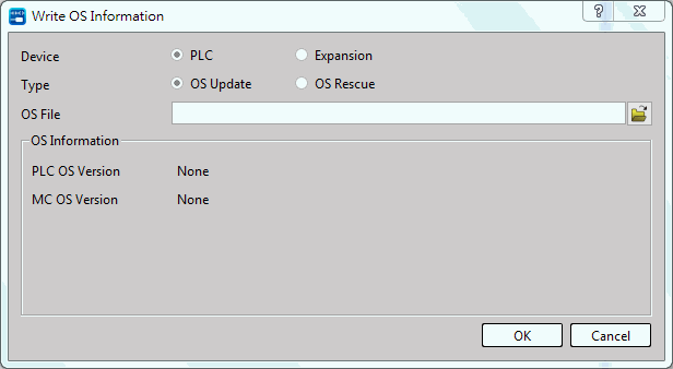
Figure 23 Firmware update or rescue
For details on how to update the firmware through the Memory Card, please refer to Section 14-2.
※If the firmware version of the expansion module is changed using the Memory Card, it needs to be disconnected from the software, and then reconnected to UperLogic before the display will be updated.
7-3 Switching Copy Protection
The copy protection function provides a protection mechanism that allows users to prevent the memory card from being misused in an unintended CPU Unit device. The memory card with copy protection turned on will be bound to the current CPU Unit, and the bound memory card will not be able to be used on other CPU Unit devices. If you want to cancel the copy protection, you need to cancel the protection on the bound CPU Unit.
Enable or disable the card and the CPU Unit serial number binding function:
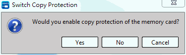
Figure 24 Enable or disable CPU Unit binding
After selecting, it will bind the serial number of the card and the current CPU Unit. After pressing “No”, the system will unlock the binding function.
7-4 Memory Card Information
After clicking, you may check the message of the card currently selected:
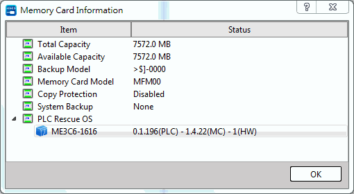
Capacity
Total capacity of the memory card.
Available Capacity
The available capacity of the memory card will be calculated after the execution of the first command, and will be ended calculating when the CPU Unit is in operation.
Backup Model
Information about the version of the CPU Unit used to create the memory card content.
Copy Protection
Enable or disable copy protection.
System Backup
CPU Unit -related information of system backup.
Update/Rescue Firmware Version
Display the updated firmware object and version information contained in the memory card content.
7-5 Reading the Data Register Being Replicated to Memory Card
●Based on the setting of R35479, the data register replicated to the Memory Card (such as the adjusted value or the fixed application value) shall be read by the Memory Card according to the value of R35479 upon each start. After that, the data register being saved in the RAM of the CPU Module shall be initialized to the value of the Memory Card at that time in order that correct operating data will be maintained.
● R35469–R35478 are used to read the data register being replicated to the Memory Card. Before replicating the Ladder program and the Register to the Memory Card, it is required to set the value of R35469–R35478 and then replicate these values to the Memory Card. When starting the machine each time, the system will execute the following actions according to R35469–RS35478 being replicated to the Memory Card.
|
Register |
Setting |
Description of Function |
|
R35469 |
A66AH |
When starting the machine each time, you may read the data register being replicated to the Memory Card according to the instructions provided in the table below (such function shall be available for the shutdown holding-type register). |
|
Other value |
The aforesaid function shall not be available when R35479 value equals to 5530H. If it is not required to run such function upon each start, you should set R35469 as “0”. |
|
|
R35470 |
1–4 |
The lot count of the data register (4 lots at most) retrieved from the Memory Card. |
|
R35471 |
Length 0 |
Reading the data length of Lot #1 registers from Memory Card: |
|
R35472 |
Start 0 |
Reading the initial address of Lot #1 registers from Memory Card: The scope of initial address to be read for R5000–R8071 registers shall be 5000–8071. |
|
R35473 |
Length 1 |
Reading the data length of Lot #2 registers from Memory Card: The scope of data length shall be the same as R35471. |
|
R35474 |
Start 1 |
Reading the initial address of Lot #2 registers from Memory Card: |
|
R35475 |
Length 2 |
Reading the data length of Lot #3 registers from Memory Card: |
|
R35476 |
Start 2 |
Reading the initial address of Lot #3 registers from Memory Card: |
|
R35477 |
Length 3 |
Reading the data length of Lot #4 registers from Memory Card: |
|
R35478 |
Start 3 |
Reading the initial address of Lot #4 registers from Memory Card: The scope of initial address shall be the same as R35472. |
Table 13 Memory Card Replication Related Register Function
7-6 Reading and Writing Memory Card through Function Instruction
To meet the applications required by different Clients, apart from using the software and the register to read and write the Memory Card, it also allows the user to read and write the commands (FUN161, FUN162) with Memory Card on the Ladder in order to read or write the data in the Memory Card flexibly. Provided below is the description and the application example of FUN161 and FUN162 commands.
FUN161 commands example:
|
FUN161P WR-MP |
Write Data Record into the MEMORY_PACK (Write memory pack) |
FUN161P WR-MP |
||||||||||||||||||||||||||||||||||||||||||||||||
|
Symbol |
||||||||||||||||||||||||||||||||||||||||||||||||||
|
|
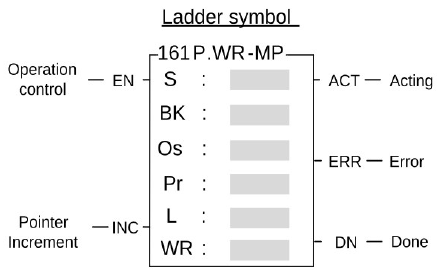
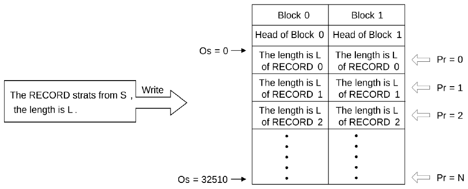
S:Starting address of the source data BK:Block number of the MEMORY_PACK,0~1 Os:Offset of the block Pr:Address of the pointer L:Quantity of writing,1~128 WR:Starting address of working registers, it takes 2 registers S may combine with V、Z、P0~P9 for indirect addressing application. |
|||||||||||||||||||||||||||||||||||||||||||||||||
|
||||||||||||||||||||||||||||||||||||||||||||||||||
|
FUN161P WR-MP |
Write Data Record into the MEMORY_PACK (Write memory pack) |
FUN161P WR-MP |
|
Description |
||
|
||

|
FUN161P WR-MP |
Write Data Record into the MEMORY_PACK (Write memory pack) |
FUN161P WR-MP |
||||
|
||||||
|
Example |
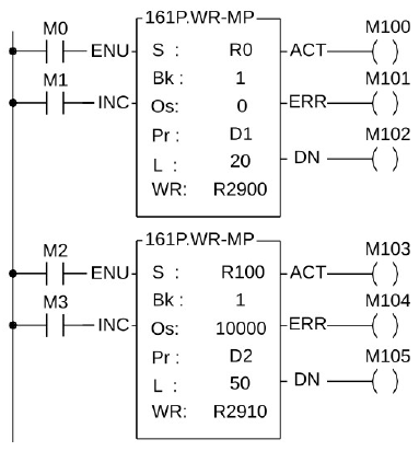
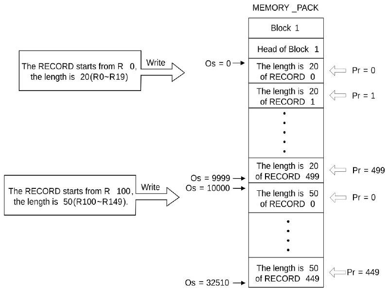
Writing the record into block 1 with the different length |
|||||
|
||||||
|
FUN161P WR-MP |
Write Data Record into the MEMORY_PACK (Write memory pack) |
FUN161P WR-MP |
|
|
||
FUN162 commands example:
|
FUN162 P RD-MP |
Read Data Record from the MEMORY_PACK (Read memory pack) |
FUN162 P RD-MP |
|||||||||||||||||||||||||||||||||||
|
Symbol |
|||||||||||||||||||||||||||||||||||||
|
|
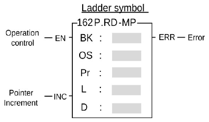
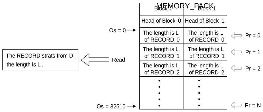
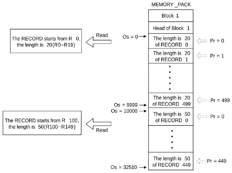
BK:Block number of the MEMORY_PACK,0~1 Os:Offset of the block Pr:Address of the pointer L:Quantity of reading,1~128 D:Starting address to store the reading record |
||||||||||||||||||||||||||||||||||||
|
|||||||||||||||||||||||||||||||||||||
|
Description |
|||||||||||||||||||||||||||||||||||||
The working diagram as shown below : |
|||||||||||||||||||||||||||||||||||||
|
FUN162 P RD-MP |
Read Data Record from the MEMORY_PACK (Read memory pack) |
FUN162 P RD-MP |
|
|
||
|
FUN162 P RD-MP |
Read Data Record from the MEMORY_PACK (Read memory pack) |
FUN162 P RD-MP |
||||
|
Example |
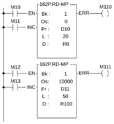
Reading the record from block 1 with the different length |
|||||
|
※ It is necessary that correct data in MEMORY_PACK or this example can’t execute correctly.
|
||||||
Tip: press ← → to switch chapters, Ctrl+K to search