Posted in

By

14 of 18Updated 2026-11-1732 min read中文版

13-1 Temperature Control Instruction Description and Examples

FUN99 P

TPCTL2

PID temperature control instruction 2(Build-in PID auto-tunning)

FUN99 P

TPCTL2

Symbol

D:\patrick\說明書翻譯_功能篇\圖\FUM99.png

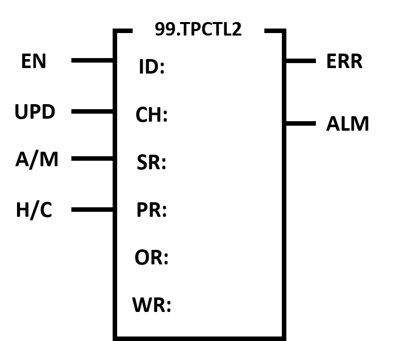
ID: The number of the expansion module used as the

input signal

CH: Channel number for input signal

SR: Process control setup start register

PR: Gain setup start register

OR: Output start register

WR: Working start register

Range

Operand

HR

IR

OR

SR

ROR

DR

K

R0

∣

R34767

R34768

|

R34895

R35024

∣

R35151

R35280

∣

R40279

R40280

∣

R48471

D0

∣

D7999

ID

0-64

CH

○

○

○

○

○

○

0-127

SR

○

○

○

0-63

PR

○

○*

○

OR

○

○*

○

WR

○

○*

○

FUN99 P

TPCTL2

PID temperature control instruction 2

FUN99 P

TPCTL2

Description

  • PID temperature control (FUN99) uses the temperature module and the temperature

planning form to measure the current external temperature value as a Process Variable (PV), and the temperature Set Point (SP) set by the user, and the program-controlled variable through the software PID mathematical formula to obtain the appropriate output control value to control the temperature within the temperature range expected by the user.

  • Convert the numerical result after PID operation into time-proportional ON/OFF (PWM) output, and control the heating or cooling circuit connected in series with the SSR through the transistor-type contact output, and you can get quite precise control results. It is also possible to control the conduction angle of the SCR or the proportional valve through the D/A analog output module to control the SCR conduction angle or the proportional valve for precise temperature control.
  • EN: Execute temperature control when ON, stop when OFF
  • UPD: When ON, the parameters will be updated to the specified channel of the module
  • A/M: PID manual mode (PID manual mode), if enabled, the output will be in manual control mode, and the MOUT value will be automatically copied to MV instead of using the PID calculation result as the output.
  • H/C: Perform heating or cooling control.

FUN99 P

TPCTL2

PID temperature control instruction 2

FUN99 P

TPCTL2

PID control

  • The PID control system is independently operated by the modules, and the PLC scan cycle will not be increased due to multiple modules performing PID at the same time.
  • Each channel will be able to execute the desired PID computation. The temperature control mode must be set as PID control in order to carry out the temperature control more efficiently through the proportional (P), integral action (I) and derivative action (D). It can also execute the P, PI, PD and PID control according to actual demand.
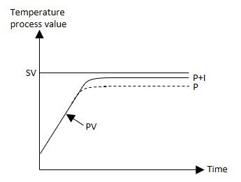
  • Proportional (proportional): The amount of output quantity (MV) will configure an output proportion according to the error (E) between the measured value (PV) and the setup value (SV). The bigger the setup of proportional, the lighter the fluctuation.
  • Integral time: The output quantity will be increased and decreased according to the error (E) between the measured value (PV) and the setup value (SV) in order to reduce the error that will be finally produced by P action. The smaller the integral time, the stronger the fluctuation and the quicker the rising; on the contrary, it will become lighter and slower. The scape is 0–3600s. If the integral time is set at “0”, then the system will not execute the integral control.

  • Derivative time (derivative time); The output quantity will be increased or decreased according to the error (E) change rate between the measured value (PV) and the setup value (SV).

Even though abrupt change has resulted due to the noise influence, it can be restored to stabilized status through the derivative action. The smaller the derivative time, the lighter the fluctuation and the slower the noise reaction; on the contrary, it will become larger and quicker. Its scope is 0–3600s. If the derivative time becomes “0”, the system will not execute the derivative control.

FUN99 P

TPCTL2

PID temperature control instruction 2

FUN99 P

TPCTL2

SR Parameter

Word size

Description

TS

1

Time cycle size,

the unit is 0.1s (0.1s~30.0s)

When Out mode=0, the TS setting time must be greater than or equal to PERIOD; if the setting time is less than PERIOD, the system will automatically set it to PERIOD.

SV

2

Set value,

the unit is 0.1 degree

DEAD BAND

1

Reach the dead band near the SV, the range is 0.1%~10.0%

DOUT

1

Output points

PERIOD

1

PWM cycle,

the unit is 100ms

Out mode

1

0, PWM output

1, else

FUN99 P

TPCTL2

PID temperature control instruction 2

FUN99 P

TPCTL2

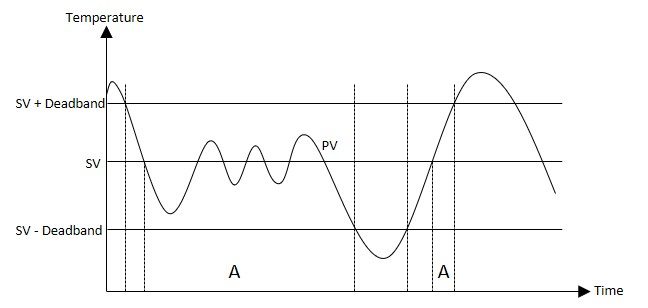
  • PID_Deadband: The setting scope is rated at 0–10.0% (input scope). During the PID control, such zone is an offset (E) inactive area. When the temperature process value (PV, temperature control value) enters such deadband, the system will still execute the PID computation until it rides through the set value (SV, setup value). At this time, the system will replace “0” with “E” to resolve in the formula. After riding through such zone, it will restore to normal status to execute the PID computation. Taking the following figure as the example, the system will take “E” in A-zone as “0”.

FUN99 P

TPCTL2

PID temperature control instruction 2

FUN99 P

TPCTL2

PR

Word size

Description

Kp

2(floating point)

Proportional,

real number

Ti

1

Integral time, 0~3600s

Td

1

Differential time, 0~3600s

Bias

2(floating point)

Output bias, real number

Output upper limit

2(floating point)

Higher output limit

Output lower limit

2(floating point)

Lower output limit

PID Method

1

0: Standard PID

1: Minimum transcending

3: Standard PID incremental mode

AT

1

Enable/Disable AT

MAUTO

1

MOUT values change with MV or not

  • Kp, Ti, Td:PID parameter, to specify or turn on the automatic generation of AT and adjust

it for use.

  • Bias:Output bias, users can use it to increase or decrease the output value, but it will still be limited by the setting of the output range.
  • High/Low output limit:Limitation of output range, to set the high and low limits of PID output. If the output lower limit is greater than or equal to the output upper limit, an error alarm will be issued.
  • PID Method:Choose the appropriate PID algorithm.
  • AT:Enable/disable Autotuning to get PID control parameters.
  • MAUTO:To copy MV values to MOUT.

OR

Word size

Description

MV

2(floating point)

Report of output values

MOUT

2(floating point)

Setting of Manual Output Values (MV)

FUN99 P

TPCTL2

PID temperature control instruction 2

FUN99 P

TPCTL2

WR

Word size

Description

PID operating state

1

=0, Idle

=1, Working

=2, Error

=3, AT now

AT working state

1

=0, Idle

=1, Running

=2, Error

=3, Finish

=4, Time out

PV

2

Programmed return values

Auto tuning

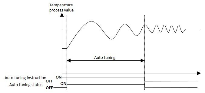
  • Based on the environment of the control system, such function will calculate the PID parameters suitable for proportional (P), integral time (I) and differential time (D) automatically and shall become active when it is required to select the PID control mode to execute the temperature control. Before this, it will execute the calculation according to the waveforms being obtained after the ON/OFF control in order to present the optimal PID parameters. After that, the system will write the parameters in the memory of the respective PID automatically where the parameter will be converted to PID control mode to carry out the temperature control.

FUN99 P

TPCTL2

PID temperature control instruction 2

FUN99 P

TPCTL2

  • During the auto tuning period, the system will execute the output according to the output upper limit and the output lower limit. The auto tuning will become active when the output cycle is not set as “0”.
  • If SV exceeds the temperature scope value, the auto tuning will not be executed.
  • If the auto tuning is not completed after being run for 2 hours, then the system will signal the auto tuning overdue error alarm.
  • The channel being set as close will not be able to execute the auto tuning function.
  • To change the value set for SV, dead band, TC module calibration, output upper limit, output cycle, control mode and channel closing, the system will stop the auto tuning and then signal the error alarm in order to trigger the relay (i.e. ON).
  • Execution method: Through temperature control command
  • Ending method: Report the ending of Auto tuning.

FUN99 P

TPCTL2

PID temperature control instruction 2

FUN99 P

TPCTL2

Auto Tuning Example

SSR Example

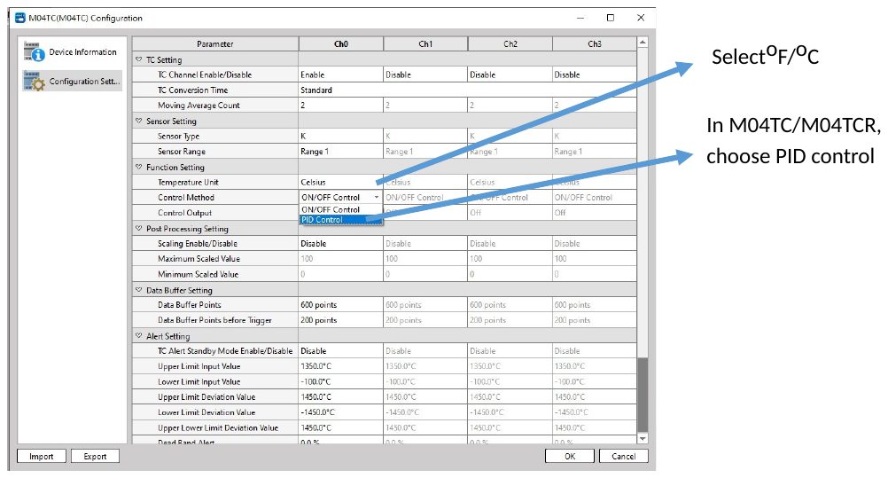
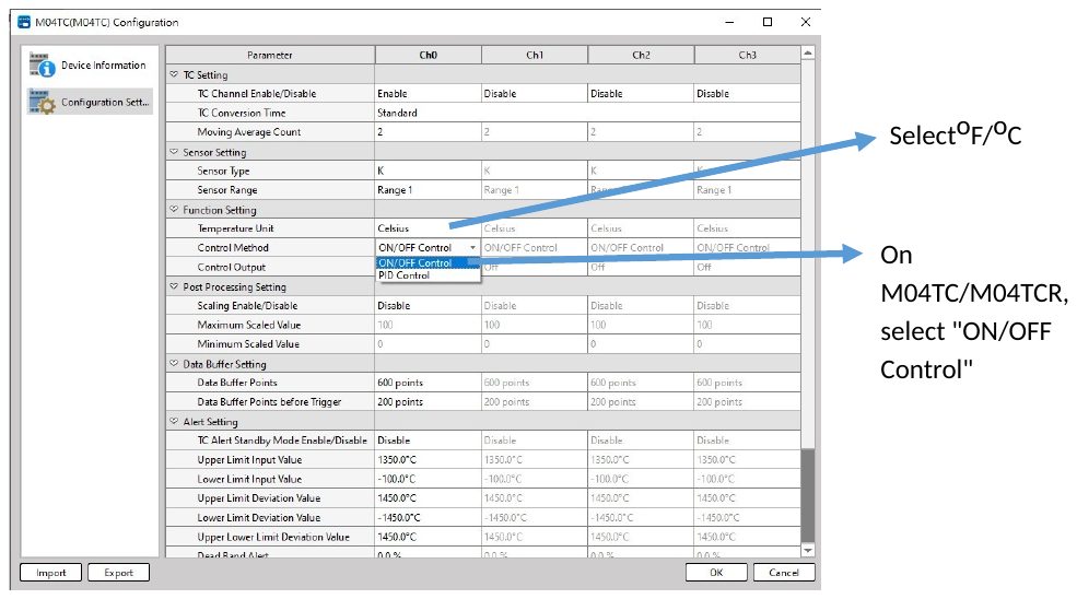
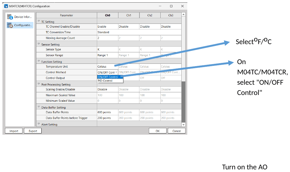
Step0 Related settings of M04TC/ M04TCR module

FUN99 P

TPCTL2

PID temperature control instruction 2

FUN99 P

TPCTL2

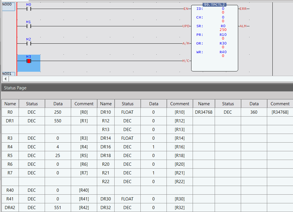
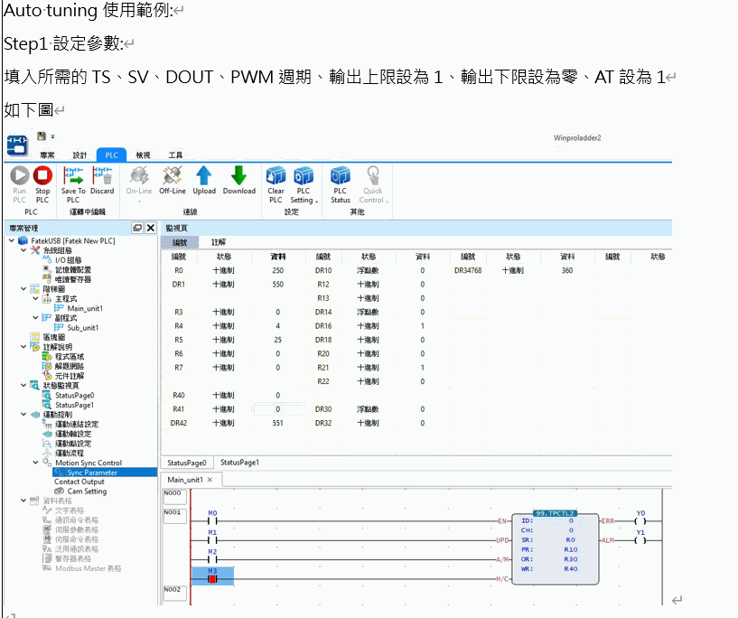
Step1 Setting parameters:

Fill in the required TS, SV, DOUT, PWM period, set the output upper limit to 1, the output lower limit to zero, and AT to 1, as shown in the figure below:

FUN99 P

TPCTL2

PID temperature control instruction 2

FUN99 P

TPCTL2

Example usage parameters and related definitions

The meaning of the corresponding parameters in the example

R0 = Control cycle (unit is 0.1s)

=25seconds.

DR1 = setting value

=55 oC /oF, determined by the setting of Step0 whether it is oC or oF.

R4 = point number of the output

=4, the table output is Y4 of the CPU Unit

R5 = PWM control period

=25, control once every 2500 milliseconds

R6= output mode

=0, PWM mode (1 is other modes, it will output MV out, allowing users to move to the required OR register)

DR16 = output upper limit

=1, 1 times of full scale (ex: K type is 1350-(-200)=1550*1 oC)

DR18 = output lower limit

=0, 0 times the full scale (same as above, please refer to the thermocouple temperature table for the full scale)

R21 = Auto tuning ON

=1, 1 ON; 0 OFF

R40 = PID state

=0, idle

R41 = Auto tuning state

=0, idle

DR42 = Programmed return value (PV)

=55.1 oC/oF

FUN99 P

TPCTL2

PID temperature control instruction 2

FUN99 P

TPCTL2

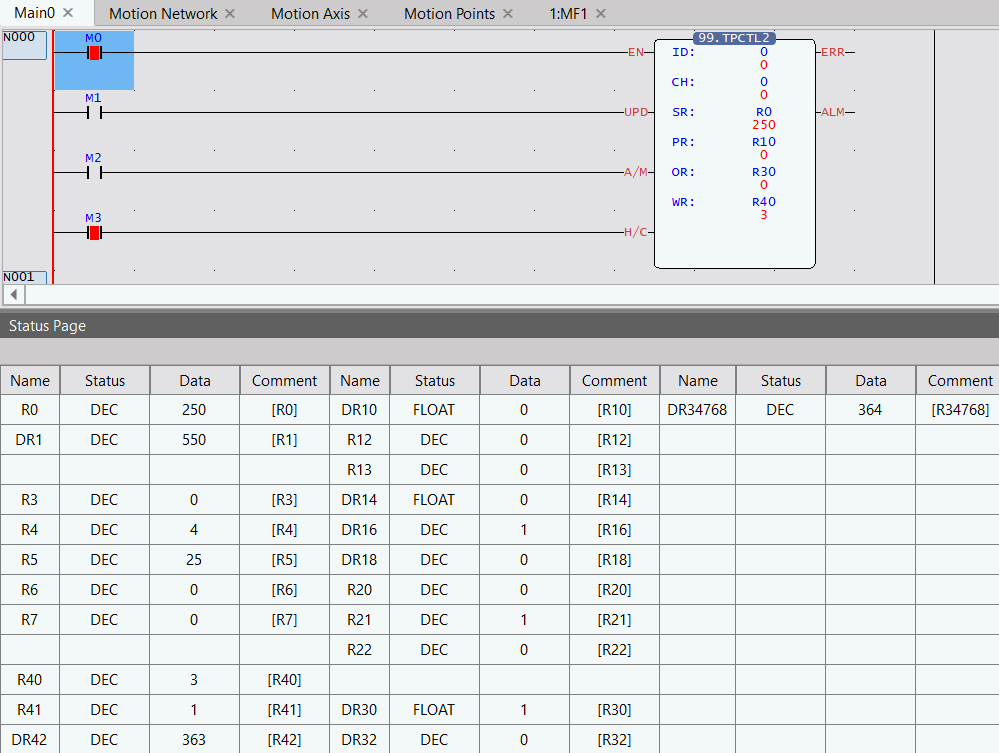
In Step2 Auto tuning:

During Auto tuning, you need to wait for relevant parameters (Kp, Ki, Kd, Auto tuning status = 3, that is, Tune is completed), and Error will be output if it exceeds 2 hours.

As shown below

Example usage parameters and related definitions

The meaning of the corresponding parameters in the example

M0=Turn on temperature control

=1, trigger command

M3=Output point output is heating or cooling

=1, heating

R40=PID state

=3, in Auto tuning

R41=Auto tuning status

=1, Auto tuning is in progress

DR42 = Programmed return value (PV)

=36.3 oC/oF

FUN99 P

TPCTL2

PID temperature control instruction 2

FUN99 P

TPCTL2

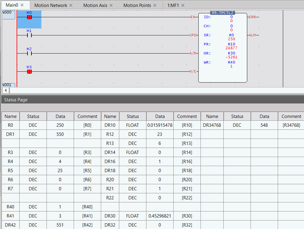
Step3 Auto tuning completed:

After Auto tuning is completed, the relevant parameters Kp, Ki, and Kd should have corresponding parameters and Auto tuning status=3

As shown below

Example usage parameters and related definitions

The meaning of the corresponding parameters in the example

M0=Turn on temperature control

=1, trigger command

M3=Output point output is heating or cooling

=1, heating

DR10=Kp, proportional item

=0.0159…… (output as floating-point number)

R12=Ki, integration time

=23, the unit is second

R13=Kd, differential time

=6, unit is second

R40=PID state

=1, PID is executing

R41=Auto tuning state

=3, Auto tuning completed

DR42 = Programmed return value (PV)

=55.1 oC/oF

FUN99 P

TPCTL2

PID temperature control instruction 2

FUN99 P

TPCTL2

On/Off mode

Example:

Step0 Related settings of M04TC/ M04TCR module

FUN99 P

TPCTL2

PID temperature control instruction 2

FUN99 P

TPCTL2

On/Off mode

Example:

Step1 Fill in the required TS, SV, dead band, DOUT, output upper limit, output lower limit, and trigger the command

Example usage parameters and related definitions

The meaning of the corresponding parameters in the example

M0=Turn on temperature control

=1, trigger command

M3=Output point output is heating or cooling

=1, heating

R0 = control period

(Unit is 0.1s)

=25 seconds

DR1 = Set value

=55oC/oF, determined by Step0 setting is oC or oF

R3= Dead band

=1, i.e., 0.1% of full scale, taking K type thermocouple as an example, when filling 1 in the temporary register, it means that 0.1% of full scale will be used as the dead band size, i.e., (1350-(-200)) *0.1% is approximately equal to 1.5 oC, the upper limit of the dead zone is 55+1.5, and the lower limit is 55-1.5 (please refer to the thermocouple temperature range table for the full scale)

R4 = Point number of the output

=4, the table output is Y4 of the CPU Unit

R5 = PWM control period

=25, control once every 2500 milliseconds

DR16 = Output upper limit

=1, 1 times of full scale (ex: K type is 1350-(-200) =1550*1 oC)

DR18 = Output lower limit

=0, it is 0 times of full scale (ex: K type is 1350-(-200) =1550*0 oC)

FUN99 P

TPCTL2

PID temperature control instruction 2

FUN99 P

TPCTL2

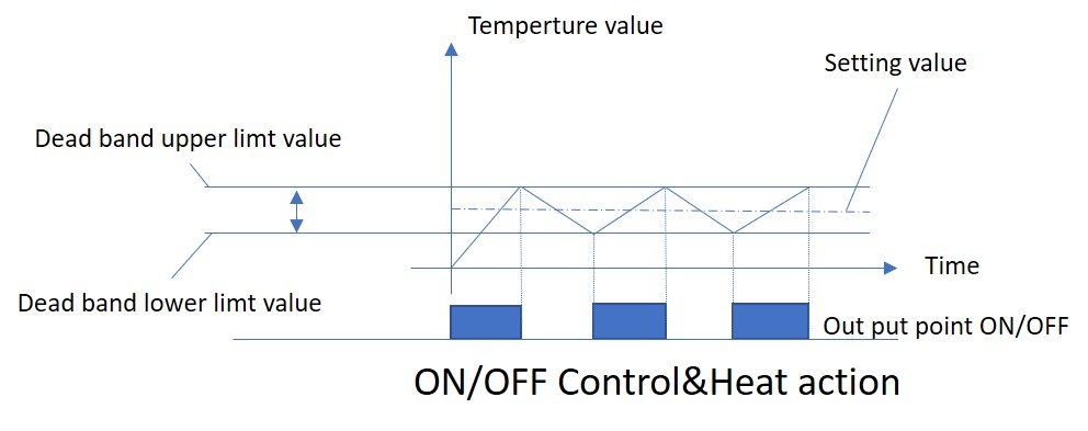
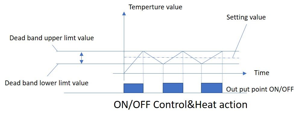
Schematic diagram of ON/OFF control action

FUN99 P

TPCTL2

PID temperature control instruction 2

FUN99 P

TPCTL2

Auto tuning Example:

SCR example, this is an example with the M04DA analog output module

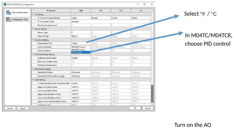
Step0

Related settings of M04TC/ M04TCR module

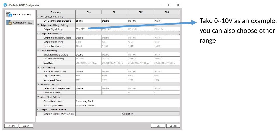
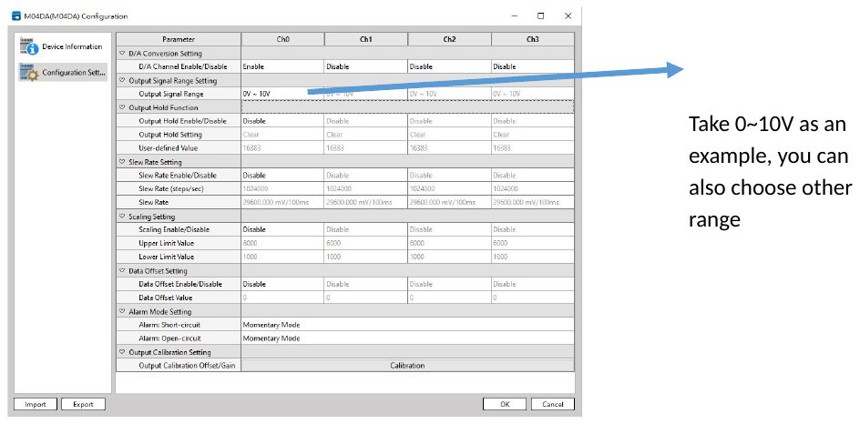
Related settings of M04DA/ M04DAR module

FUN99 P

TPCTL2

PID temperature control instruction 2

FUN99 P

TPCTL2

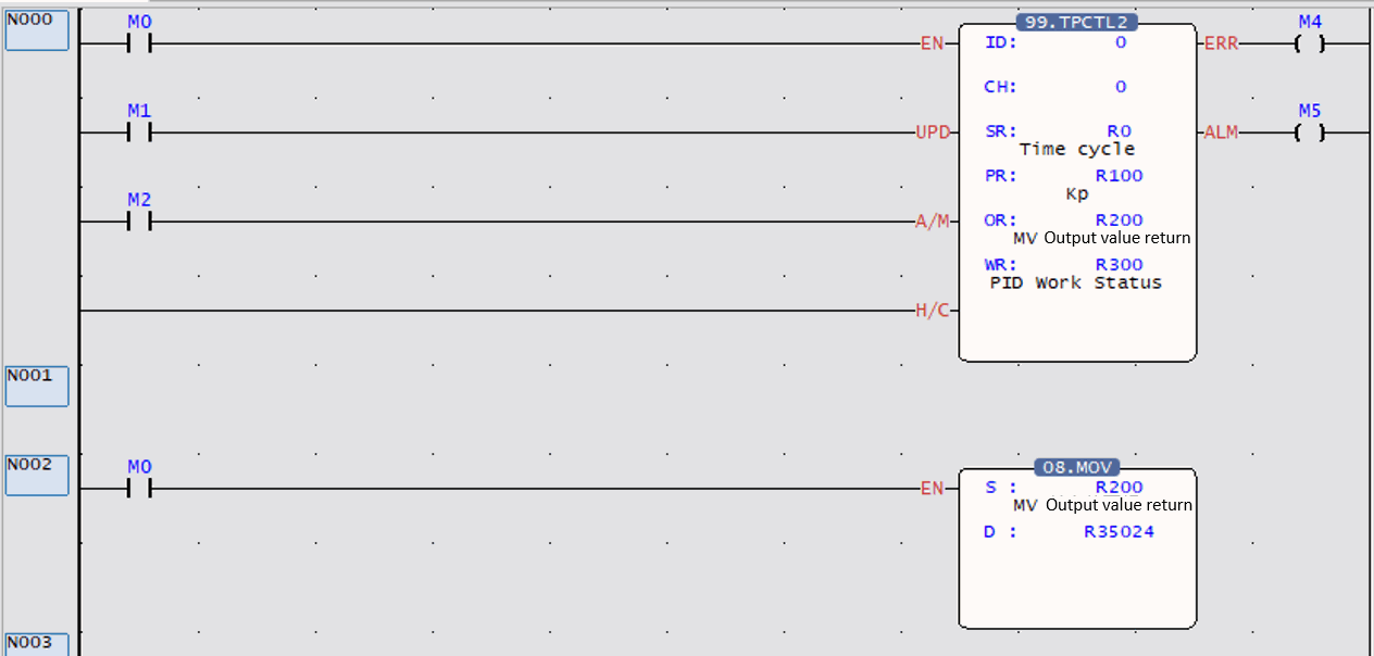
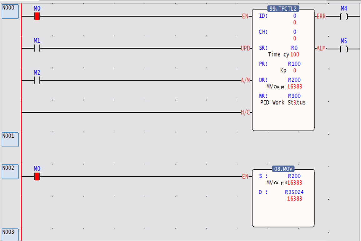
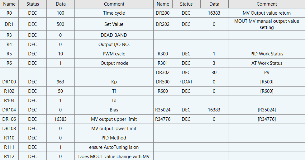
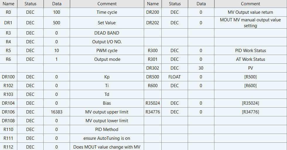
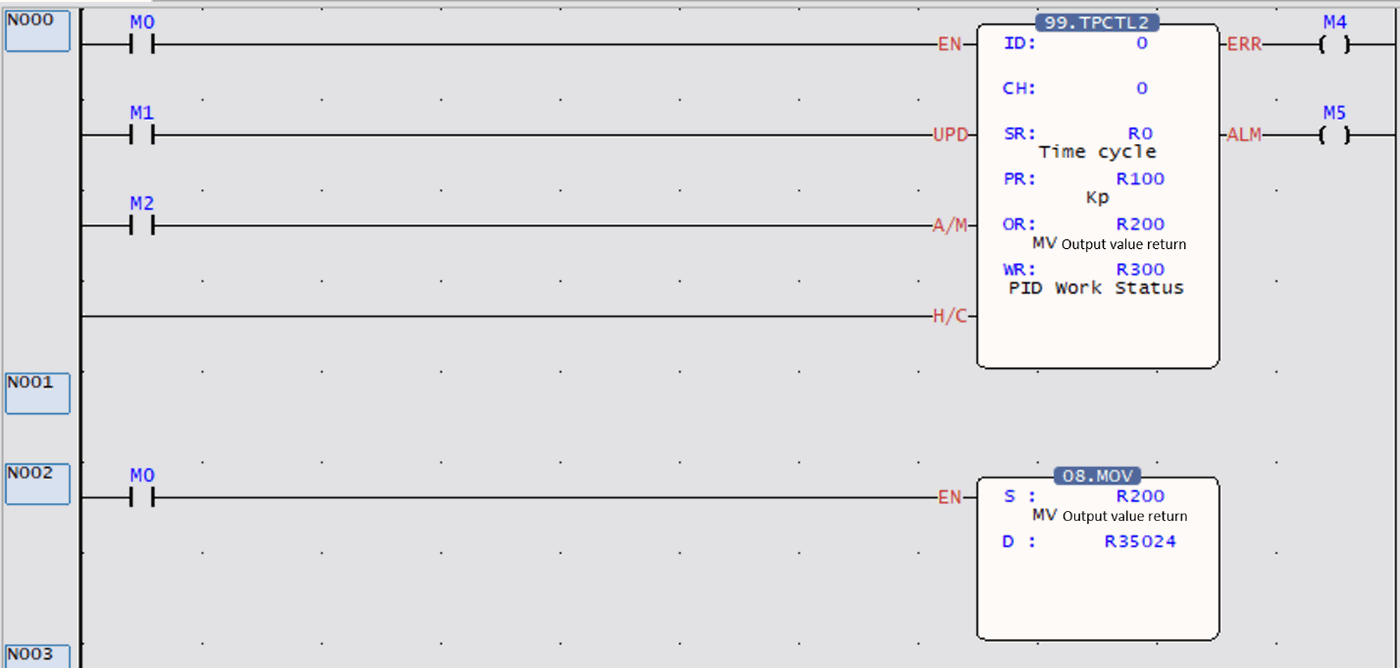
Step1 Setting parameters: Setting parameters and ladder diagram program, the detailed content and explanation of the table are on the next page

FUN99 P

TPCTL2

PID temperature control instruction 2

FUN99 P

TPCTL2

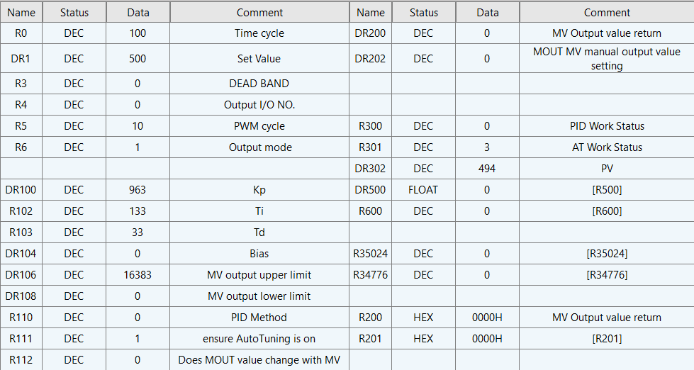
Example usage parameters and related definitions

The meaning of the corresponding parameters in the example

R0 = control period (unit is 0.1 second)

=100(10 seconds)

DR1 = set value (unit 0.1 degree)

=500(50.0oC/oF), determined by the M04TC module setting

R5=PWM output period (unit 100 millisecond)

=10(1 seconds)

R6= output mode

=1, other modes (0 is PWM mode, it will output according to the set output point

DR106=Output upper limit

=16383 (corresponding to the upper limit of the digital value of the M04DA module)

DR108=output lower limit

=0 (corresponding to the lower limit of the digital value of the M04DA module)

R111=AT open

=1 (AT is on)

R300=PID state

=0(idle)

R301=AT state

=1(idle)

R21 = Auto tuning ON

=1, 1 ON; 0 OFF

R40 = PID state

=0, idle

R41 = Auto tuning state

=0, idle

DR302=Programmed value return

=494 (49.4oC/oF)

The command H/C is short-circuited, which means that when there is output, it is heating control; if it is empty, it means cooling control

After filling in the above setting values, you can turn M0 ON, trigger the command and perform Autotuning.

FUN99 P

TPCTL2

PID temperature control instruction 2

FUN99 P

TPCTL2

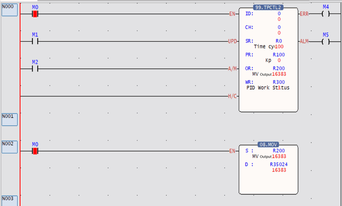
In Step2 Auto tuning:

During Auto tuning, you only need to wait for relevant parameters (Kp, Ki, Kd appear, Auto tuning status = 3, that is, Tune is completed, you can enter Step 3), and Error will be output if it exceeds 2 hours.

As shown below

FUN99 P

TPCTL2

PID temperature control instruction 2

FUN99 P

TPCTL2

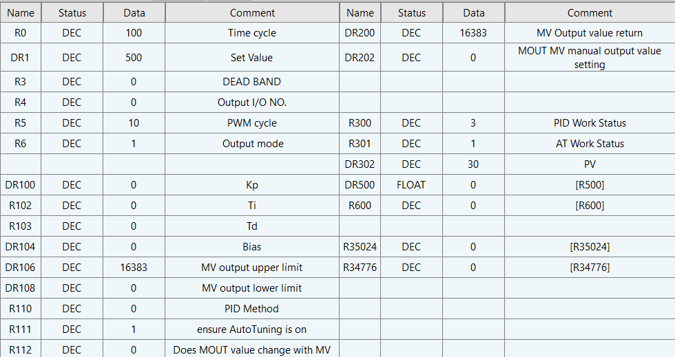
Example usage parameters and related definitions

The meaning of the corresponding parameters in the example

M0=Turn on temperature control

=1, trigger command

H/C= stands for heating/cooling control

=1, for heating control (ex: connected to a heating rod to control heating)

R300=PID state

=3, in Auto tuning

R301=AT state

=1, Auto tuning is running

DR42 = Programmed return value (PV)

=36.3 oC/oF

DR200=MV output value, for integer output

=16383, it is the output control value after instruction operation

R35024=OR register,

This example is CH0 of M04DA output channel register

=16383 (the value transferred into R200 by instruction FUN8)

FUN99 P

TPCTL2

PID temperature control instruction 2

FUN99 P

TPCTL2

Step3 Auto tuning completed:

After Auto tuning is completed, the relevant parameters Kp, Ki, and Kd should have corresponding parameters and Auto tuning status=3

As shown below:

FUN99 P

TPCTL2

PID temperature control instruction 2

FUN99 P

TPCTL2

Example usage parameters and related definitions

The meaning of the corresponding parameters in the example

R300=PID state

=1 (PID is executing)

R301=AT state

=3(AT completed)

R111=AT open

=1 (AT is on)

DR100=Kp, proportional item

=963 (for floating point output)

R102=Ki, integral time

=50, unit is second

R103=Kd, differential time

=1, unit is second

DR200=MV output value (for integer output)

=16383, it is the output control value after instruction operation

FUN99 P

TPCTL2

PID temperature control instruction 2

FUN99 P

TPCTL2

On/Off mode

Example:

Step0

Related settings of M04TC/ M04TCR module

Related settings of M04DA/M04DAR module

FUN99 P

TPCTL2

PID temperature control instruction 2

FUN99 P

TPCTL2

On/Off mode

Example:

Step1 Setting parameters: Setting parameters and ladder diagram program, the detailed content and explanation of the table are on the next page

FUN99 P

TPCTL2

PID temperature control instruction 2

FUN99 P

TPCTL2

Example usage parameters and related definitions

The meaning of the corresponding parameters in the example

M0=Turn on temperature control

=1, trigger command

H/C = Heating Cooling Control

=1 (short connection), 1 for heating control; 0 for cooling control

R0=control cycle (unit 0.1S)

=100(10 seconds)

DR1=set value (unit 0.1 degree)

=500(50.0oC/oF), determined by the M04TC module setting

R3= dead band

=1, 0.1% of full scale, taking K type thermocouple as an example, when filling 1 in the temporary register, it means that 0.1% of full scale will be used as the dead band size

, that is (1350-(-200)) *0.1% is approximately equal to 1.5oC, the upper limit of the dead zone is 55+1.5, and the lower limit is 55-1.5 (please refer to the thermocouple temperature range table for the full scale)

R5 = PWM control period

=10, control once every 1 seconds

R6=Output mode

=1 (Other output, namely MV output scratchpad output)

DR302=Programmed value return

=30 (3.0oC/oF)

DR106 = Output upper limit

=16383 (corresponding to the upper limit of the digital value of the M04DA module)

DR108 = Output lower limit

=0 (the lower limit of the digital value of the M04DA module)

Schematic diagram of ON/OFF control action

13-2 General-Purpose PID Control Instruction Description and Examples

FUN38

PID2

PID 2

FUN38

PID2

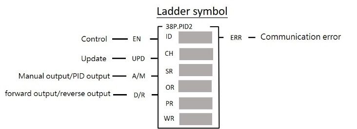
Symbol

ID: The number of the expansion module used as the input signal.

CH: Channel number for input signal.

SR: The starting register number of the program-controlled setting value, occupying 8 registers in total.

OR: PID output register number

PR: The starting register number of the parameter setting value, occupying 7 registers in total

WR: The initial number of the working register used by this command occupies 5 registers in total, and cannot be reused in other places.

Range

Operand

HR

IR

SR

ROR

DR

K

R0

∣

R34767

R34768

∣

R34895

R35280

∣

R43223

R43224

∣

R47319

D0

∣

D7999

ID

0~127

CH

○

○

○

○

○

0 ~ 63

SR

○

○

○

OR

○

○*

○

PR

○

○

○

WR

○

○

○

Function Description

FUN38

PID2

PID 2

FUN38

PID2

  • The general-purpose PID2 command (FUN38) regards the currently measured external analog input value as a process variable (Process Variable, referred to as PV), and uses the set point (Set Point, referred to as SP) set by the user to process the variable through After the software PID mathematical calculation, the appropriate output control value is obtained through the D/A analog output module or reprocessed through other interfaces to control the controlled program within the user’s desired setting range.
  • The digitalize PID calculation formula is as follows:

Mn = [KpxEn]- [KpxTdx(PVn-PVn-1)/Ts] + Bias

Mn = Control output at "n" time

Kp: Proportional term real number (Range: ±(1.8*10-38~3.4*1038))

Ti: Integral time constant (range: 0~3600, equivalent to 0~3600 Repeats/Seconds)

Td: Derivative time constant (range: 0~3600, equivalent to 0~3600 Seconds)

PVn: Program-controlled variable value at "n" time

PV n-1: The value of the program-controlled variable last time "n"

En: Error at "n" time = set value (SP) – program variable value (PVn) at "n" time

Ts: Interval time between PID operations (Range: 1~300, unit: 0.1s)

Bias: Bias output (Range:±(1.8*10-38~3.4*1038))

FUN38

PID2

PID 2

FUN38

PID2

  • When the control selection "A/M"=0, it means the manual control mode, and the PID operation will not be executed. Directly filling the output register (OR) can control the analog output to control the program-controlled response.
  • When the control selection "A/M"=1, it represents the automatic control mode, the value of the output register (OR) is calculated by PID, and the program-controlled load is controlled through the analog output module or other interfaces to implement closed-loop program control.
  • When the control selection "A/M"=1 and the operation direction "D/R"=1, the program control is forward PID control; that is, when the error (SP-PVn) is positive, the control output of the PID operation result, the larger the value is; when the error is negative, the control output of the PID calculation result is smaller.
  • When the control selection "A / M" = 1 and the operation direction "D/R" = 0, the program control is reverse PID control; that is, when the error (SP-PVn) is positive, the control output of the PID operation result, the smaller the value is; when the error is negative, the control output of the PID operation result is larger.
  • When the program control setting value or parameter setting value is wrong, the PID instruction will not be executed, and the error indicator "ERR"=1 is set.
  • If you want to update the parameters, turn UPD OFF->ON after updating the content of the relevant register.

FUN38

PID2

PID 2

FUN38

PID2

SR Parameter

Word size

Description

TS

1

Time cycle size, unit: 0.1s(0.1s~30.0s)

SV

2

Set value, unit: 0.1 degree

DEAD BAND

1

Reach the dead band near the SV, the range is 0.1%~10.0%

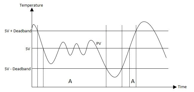
  • PID_Deadband setting range is 0~10.0% (input range). In PID control, this area is a bias (E) inactive area. When the temperature process value (PV) enters the dead band at the beginning, it will still operate PID normally. The operation is performed until the set value (SV) is crossed, then the E will be substituted into the formula with 0, and the normal PID operation will resume after crossing this area. For example, E in area A in the figure is regarded as 0.

FUN38

PID2

PID 2

FUN38

PID2

PR

Word size

Description

Kp

2(floating point)

Proportional item,

real number

Ti

1

Integral time, 0~3600s

Td

1

Differential time, 0~3600s

Bias

2(floating point)

Proportional,

real number

High output limit

2(floating point)

Integral time, 0~3600s

Low output limit

2(floating point)

Differential time, 0~3600s

PID Method

1

0: Standard PID

1: Minimum Transcendence Method

3: Standard PID Incremental Mode

BUM

2

Smooth transfer enables (1: enable, 0: disable), it is a function of smooth transfer when manual to automatic control mode.

AT

1

Enable/Disable AT

MAUTO

1

MOUT values change with MV or not

  • Kp, Ti, Td:PID parameter, to specify or turn on the automatic generation of AT and adjust

it for use.

  • Bias:Output bias, users can use it to increase or decrease the output value, but it will still be limited by the setting of the output range.
  • High/Low output limit:Limitation of output range, to set the high and low limits of PID output. If the output lower limit is greater than or equal to the output upper limit, an error alarm will be issued.
  • PID Method:Choose the appropriate PID algorithm.
  • AT:Enable/disable Autotuning to get PID control parameters.
  • MAUTO:To copy MV values to MOUT.

FUN38

PID2

PID 2

FUN38

PID2

WR

Word size

Description

PID Operating State

1

=0, Idle

=1, Working

=2, Error

=3, AT now

AT Working State

1

=0, Idle

=1, Running

=2, Error

=3, Finish

=4, Time out

PV

2

Programmed return value

OR

Word size

Description

MV

2(floating point)

Report of output values

MOUT

2(floating point)

Setting of Manual Output Values (MV)

FUN38

PID2

PID 2

FUN38

PID2

Auto tuning Example:

SCR example, this is an example of M04DA analog output and M04AD analog input module

Step0

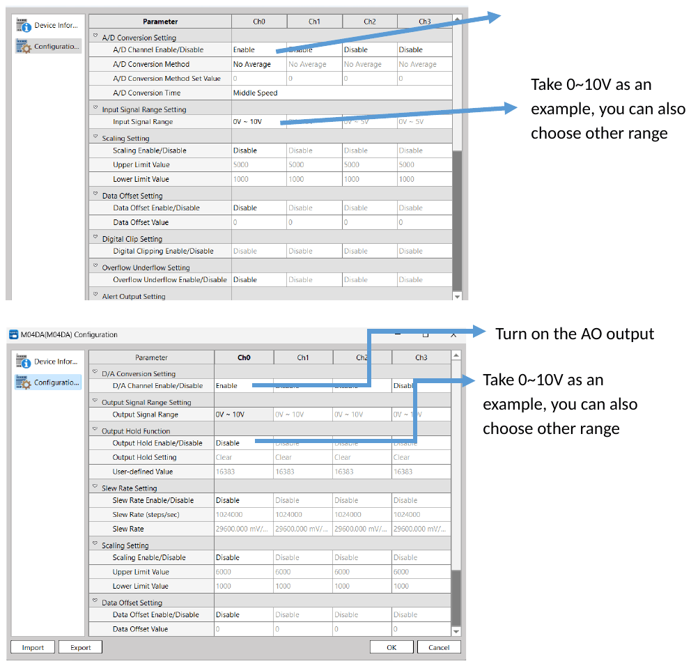
Open the conversion channel of the analog input

Related settings of M04DA/ M04DAR module

Related settings of M04DA/ M04DAR module

FUN38

PID2

PID 2

FUN38

PID2

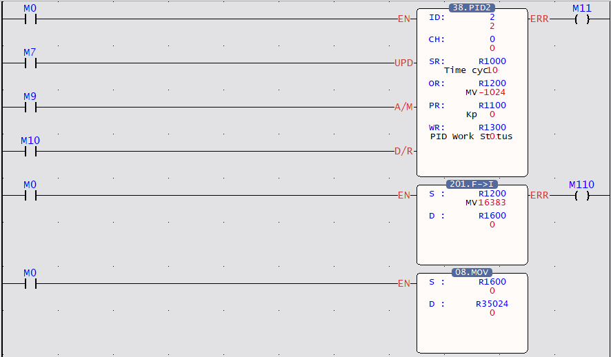
Step1 Setting parameters: Setting parameters and ladder diagram program, the detailed content and explanation of the table are on the next page.

FUN38

PID2

PID 2

FUN38

PID2

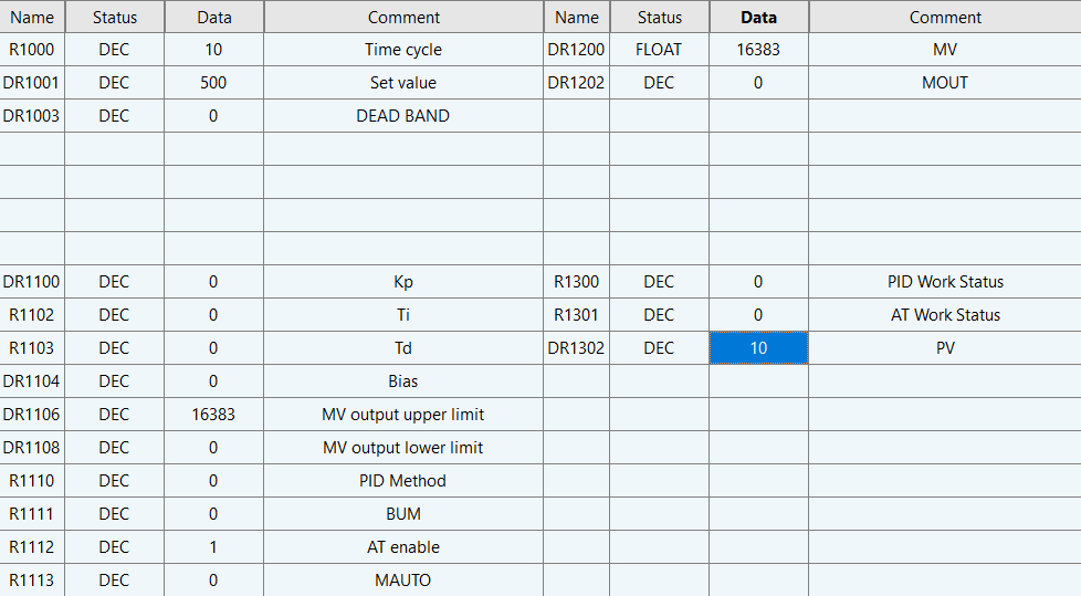
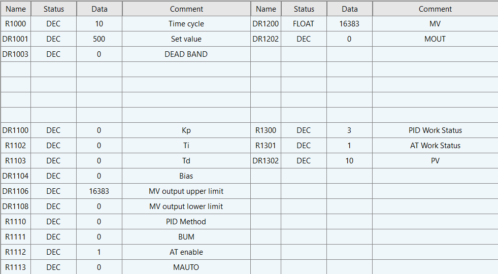
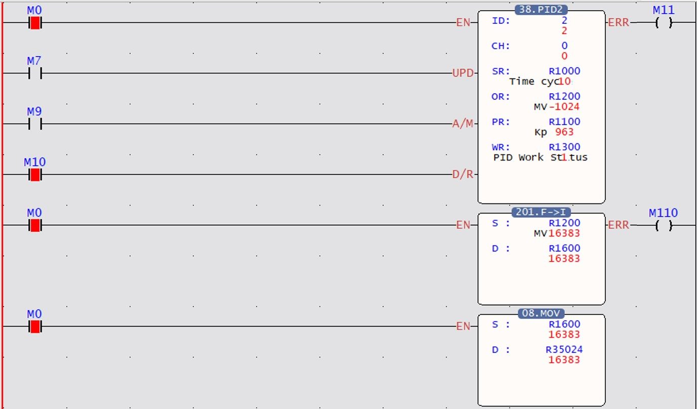
Example usage parameters and related definitions

The meaning of the corresponding parameters in the example

R1000 = Control Period (unit is 0.1 second)

=10(10 seconds)

DR1001 = Set Value (unit 0.1 degree)

=500, the reading value of the module set by the command, take this example as the reading value of channel 0 with module ID 2

DR1106=Output upper limit

=16383 (corresponding to the upper limit of the digital value of the M04DA module)

DR1108=Output lower limit

=0 (corresponding to the lower limit of the digital value of the M04DA module)

R1112=AT ON

=1 (AT is on)

R1300=PID State

=0(Idle)

R1301=AT State

=0(Idle)

DR1302=Programmed Value Return

=10

The command H/C is short-circuited, which means that when there is output, it is heating control; if it is empty, it means cooling control.

After filling in the above setting values, you can turn M0 ON, trigger the command and perform Autotuning.

FUN38

PID2

PID 2

FUN38

PID2

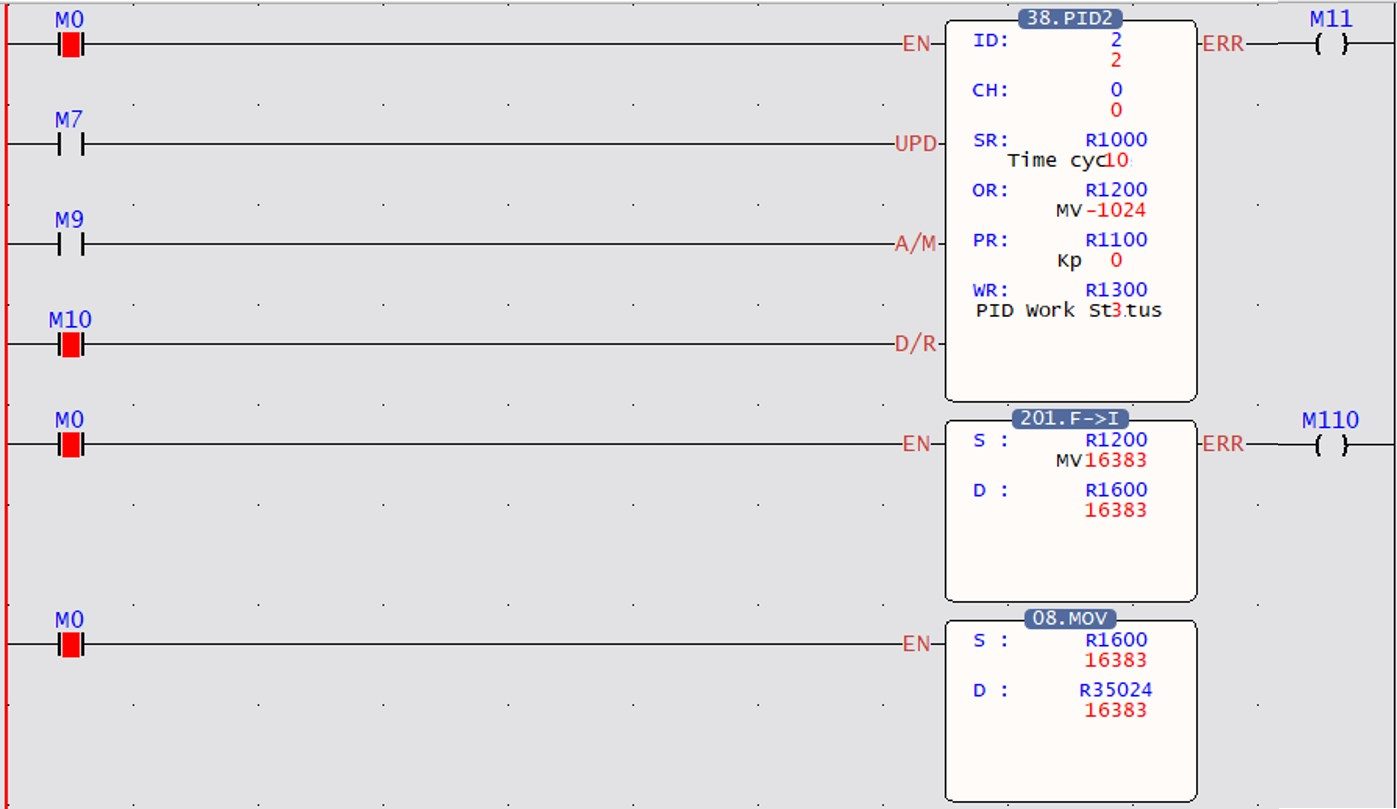
In Step2 Auto tuning:

During Auto tuning, you only need to wait for relevant parameters (Kp, Ki, Kd appear, Auto tuning status = 3, that is, Tune is completed, you can enter Step 3), and Error will be output if it exceeds 2 hours.

As shown below:

FUN38

PID2

PID 2

FUN38

PID2

Example usage parameters and related definitions

The meaning of the corresponding parameters in the example

M0=Enable PID control =1, trigger command

M0=Enable PID control =1, trigger command

D/R= stands for forward/reverse control

=1, for positive control (ex: AO voltage rise)

R1300=PID state

=3, Auto tuning

R1301=AT state

=1, Auto tuning executing

DR1302 = Programmed return value (PV)

=10

DR200=MV output value, output as floating-point number

=16383, it is the output control value after instruction operation

R35024=OR register,

This example is CH0 of M04DA

output channel register

=16383 (the value of R1600 converted into an integer by instruction FUN8 into R1600 by instruction FUN201)

FUN38

PID2

PID 2

FUN38

PID2

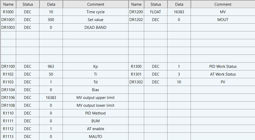
Step3 Auto tuning completed:

After Auto tuning is completed, the relevant parameters Kp, Ki, and Kd should have corresponding parameters and Auto tuning status=3

As shown below:

FUN38

PID2

PID 2

FUN38

PID2

Example usage parameters and related definitions

The meaning of the corresponding parameters in the example

R300=PID state

=1 (PID is executing)

R301=AT state

=3(AT completed)

R111=AT open

=1 (AT is on)

DR100=Kp, proportional item

=963 (for floating point output)

R102=Ki, integral time

=50, unit is second

R103=Kd, differential time

=1, unit is second

DR200=MV output value (for integer output)

=16383, it is the output control value after instruction operation

13-3 General PID operation (Main Unit)

FUN30

PID

General PID operation

FUN30

PID

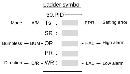
Symbol

Ts:Solution interval between calculations
(1~3000 ; unit in 0.01S)

SR:Starting register of loop settings ;
it takes 8 registers in total.

OR:Output register of PID loop operation.

PR:Starting register of loop parameters;
it takes 7registers.

WR:Staring register of working registers for this instruction ,it takes 5 registers and can’t be repeated in using.

Range

Operand

R

ROR

D

K

R0

∣

R34767

R43224

∣

R47319

D0

∣

D7999

Ts

○

○

○

1~3000

SR

○

○*

○

OR

○

○*

○

PR

○

○*

○

WR

○

○*

○

Description

FUN30

PID

PID

FUN30

PID

  • The M PLC software algorithm uses mathematical functions to simulate a three-mode (PID) analog controlling technique to provide direct digital control. The control technique responds to an error with an output signal. The output is proportional to the error, the error’s integral and the rate of change of the process variable. Control algorithms include, P, PI, PD and PID which all include the features of auto/manual operation, bumpless/balanceless transfers, reset wind-up protection, and adaptive tuning of gain, integral, and derivative terms.
  • The digitized mathematical expression of M PLC PID instruction as bellows:

Mn : Control output at "n" time

Mn

R35765 :The gain constant, the default is 1000, which can be set between 1~5000.

Pb :Proportional band

The expression stating the percent change in error required to change the output full scale. ( Range:1~5000,unit in 0.1%;Kc(gain)=R35765/P )

Ki : Integral tuning constant(range:0~9999,it means 0.00~99.99 Repeats/Minute)

Td : Derivative tuning constant(range:0~3600,equivalent to 0~3600 Seconds)

: Process variable at time "n"

:Process variable when loop was last solved

En : The difference between the set point (SP) and the process variable (PV) at time "n".

En = SP – .

Ts : Solution interval between calculations(Range:1~3000, unit in 0.01S)

Bias : Offset to the output(Range:0~16383)

FUN30

PID

PID

FUN30

PID

Principle of PID parameter adjustment

  • As the proportional band (Pb) adjustment getting smaller, the larger the proportional contribution to the output. This can obtain a sensitive and rapid control reaction. However, when the proportional band is too small, it may cause oscillation. Do the best to adjust “Pb” smaller (but not to the extent of making oscillation), which could increase the process reaction and reduce the steady state error.
  • Integral item may be used to eliminate the steady state error. The larger the number (Ki, integral tuning constant), the larger the integral contribution to the output. When there is steady state error, adjust the “Ki” larger to decrease the error.
    When the “Ki” = 0, the integral item makes no contribution to the output.
    For ex, if the reset time is 6 minutes, Ki=100/6=17;if the integral time is 5 minutes, Ki=100/5=20.
  • Derivative item may be used to make the process smoother and not too over shoot. The larger the number (Td, derivative tuning constant), the larger the derivative contribution to the output. When there is too over shoot, adjust the “Td” larger to decrease the amount of over shoot.
    When the “Td” = 0, the derivative item makes no contribution to the output.
    For ex, if the rate time is 1 minute, then the Td = 100; if the rate time is 2 minutes, then the Td = 200.
  • Properly adjust the PID parameters can obtain an excellent result for loop control.

FUN30

PID

PID

FUN30

PID

Instruction description

  • When control input "A/M"=0, it performs manual control and will not execute the PID calculation. Directly fill the output value into the output register (OR) to control the loop operation.
  • When control input "A/M"=1, it defines the auto mode of loop control; the output of the loop operation is loaded by the PID instruction every time it is solved. It is equal to Mn (control loop output) in the digital approximation equation.
  • When control input "BUM"=1, it defines bumpless transfer while the loop operation changing from manual into auto mode.
  • When control input "A/M"=1, and direction input "D/R"=1, it defines the direct control for loop operation;
    it means the output increases as error increases
  • When control input "A/M"=1, and direction input "D/R"=0, it defines the reverse control for loop operation;
    it means the output decreases as error increases
  • When comes the error setting of loop setting points or loop parameters, the PID operation will not be performed and the output indication "ERR" will be ON
  • While the engineering value of the controlling process is greater than or equal to the user set High Limit, the output indication "HAL" will be ON regardless of "A/M" state.
  • While the engineering value of the controlling process is less than or equal to the user set Low Limit, the output indication "LAL" will be ON regardless of "A/M" state.
  • Description of operand Ts:
  • Ts:It defines the solution interval between PID calculations, the unit is in 0.01 sec; this term may be constant or variable data.

FUN30

PID

PID

FUN30

PID

  • Description of operand SR (Loop setting registers):
  • SR+0 = Scaled Process Variable:This register is loaded by the PID instruction every time it gets solved. A linear scaling is done on SR+6 using the high and low engineering range found in SR+4 and SR+5.
  • SR+1 = Setpoint (SP) :The user must load this register with the desired setpoint the loop should control at. The setpoint is entered in engineering units, it must be the range:LER ≦ SP ≦ HER
  • SR+2 = High Alarm Limit (HAL): The user must load this register with the value at which the process variable should be alarmed as a high alarm (above the setpoint). This value is entered as the actual alarm point in engineering units and it must be the range:LER ≦ LAL < HAL ≦ HER
  • SR+3 = Low Alarm Limit (LAL): The user must load this register with the value at which the process variable should be alarmed as a low alarm (below the setpoint). This value is entered as the actual alarm point in engineering units and it must be the range:LER ≦ LAL < HAL ≦ HER
  • SR+4 = High Engineering Range (HER): The user must load this register with the highest value for which the measurement device is spanned. (For example a thermocouple might be spanned for 0 to 500 degrees centigrade, resulting in a 0 to 10V analog input to the M PLC (0V=0℃, 10V=500℃); the high engineering range is 500, this is the value entered into SR+4.) The high engineering range must be:-9999 < HER ≦ 19999
  • SR+5 = Low Engineering Range (LER):The user must load this register with the lowest value for which the measurement device is spanned. The low engineering range must be:-9999 ≦ LER ≦ LAL < HAL ≦ HER .
  • SR+6 = Raw Analog Measurement (RAM):The user’s program must load this register with the process variable (measurement). It is the value that the content of analog input register(R34768〜R34895)is added by the offset if necessary. It must be the range:0 ≦ RAM ≦ 16380 if the analog input is 14-bit format but valid 12-bit resolution, and 0 ≦ RAM ≦ 16383 if the analog input is 14-bit format and valid 14-bit resolution.The resolution of analog input can be defined by register R35764, R35764=0, it means 14-bit format but valid 12-bit resolution ; R35764=1, it means 14-bit format and valid 14-bit resolution.

FUN30

PID

PID

FUN30

PID

  • SR+7 = Offset of Process Variable (OPV):The user must load this register with the value as described follows: OPV must be 0 if the raw analog signal and the measurement span of the analog input module are all 0〜20mA, there is no loss of the measurement resolution; OPV must be 3276 if the raw analog signal is 4〜20mA but the measurement span of the analog input module is 0〜20mA, there will have few loss of the measurement resolution(16383×4 / 20 = 3276). It must be the range: 0 ≦ OPV < 16383 .
  • When the setting mentioned above comes error, it will not perform PID operation and the output indication "ERR" will be ON.
  • Description of operand OR:
  • OR:Output register, this register is loaded directly by the user while the loop in manual operation mode. While the loop in auto operation mode, this register is loaded by the PID instruction every time it is solved. It is equal to Mn (control loop output) in the digital approximation equation. It must be the range:0 ≦ OR ≦ 16383
  • Description of operand PR (Loop parameters):
  • PR+0 = Proportional Band (Pb):The user must load this register with the desired proportional constant. The proportion constant is entered as a value between 1 and 5000 where the smaller the number, the larger the proportional contribution.

(This is because the equation uses R35765 divided by Pb.)

It must be the range:1 ≦ Pb ≦5000, unit is in 0.1%.

Kc(gain)=R35765/ Pb; the default of R35765 is 1000, and it’s range is 1 ≦ R35765 ≦ 5000.

  • PR+1 = Integral tuning Constant (Ki):The user may load this register to add integral action to the calculation. The value entered is "Repeats/Minute" and is entered as a number between 0 and 9999. (The actual range is 00.00 to 99.99 Repeats/Minute.) The larger the number, the larger the integral contribution to the output.

It must be the range:0 ≦ Ki ≦ 9999 (0.00~99.99 Repeats/Minute)

  • PR+2 = Rate Time Constant (Td):The user may load this register to add derivative action to the calculation. The value is entered as minutes and entered as a number between 0 and 9999. (The actual range is 0.00 to 99.99 minutes.) The larger the number, the larger the derivative contribution to the output.

It must be the range:0 ≦ Td ≦ 9999 (0.00~99.99 Minutes)

FUN30

PID

PID

FUN30

PID

  • PR+3 = Bias:The user may load this register if a bias is desired to be added to the output when using PI or PID control. A bias must be used when running proportional only control. The bias is entered as a value between 0 and 16383 and is added directly to the calculated output. Bias is not required for most applications and may be left at 0.

It must be the range:0 ≦ Bias ≦ 16383

  • PR+4 = High Integral Wind_up Limit (HIWL):The user must load this register with the output value, (1 to 16383), at which the loop shoud go into "anti-reset wind-up" mode. Anti-reset wind-up consists of solving the digital approximation for the integral value. For most applications this should be set to 16383.

It must be the range:1 ≦ HIWL ≦ 16383

  • PR+5 = Low Integral Wind_up Limit (LIWL):The user must load this register with the output value, (0 to 16383), at which the loop shoud go into "anti-reset wind-up" mode. It functions in the same manner as PR+4. For most applications this should be set to 0.

It must be the range:0 ≦ LIWL ≦ 16383

  • PR+6 = PID Method:

=0 , Standard PID method;

=1 , Minimum Overshoot Method;

Method 0 is prefer because most applications using PI control (Td=0).

The user may try method 1 when using PID control and the result is not stable.

  • When the setting mentioned above comes error, it will not perform PID operation and the output indication "ERR" will be ON.

FUN30

PID

PID

FUN30

PID

  • Description of operand WR (Working registers):
  • WR+0 = Loop status register :

Bit0 =0 , Manual operation mode

=1 , Auto mode

Bit1 : This bit will be a 1 during the scan the solution is being solved,

and it is ON for a scan time.

Bit2=1 , Bumpless transfer

Bit4 : The status of "ERR" indication

Bit5 : The status of "HAL" indication

Bit6 : The status of "LAL" indication

  • WR+1 = Loop timer register:This register stores the cyclic timer reading from the system’s 1ms cyclic timer each time the loop is solved. The elapsed time is calculated by calculating the difference between the current reading of the system’s 1ms cyclic timer and the value stored in this register. This difference is compared to 10× the solution interval. If the difference is greater than or equal to the solution interval, the loop should be solved this scan.
  • WR+2 = Low order integral summation:This register stores the low order 16 bits of the 32-bit sum created by the integral term.
  • WR+3 = High order integral summation:This register stores the high order 16 bits of the 32-bit sum created by the integral term.
  • WR+4 = Process variable – previous solution:The raw analog input (Register SR+6) at the time the loop was last sovled. This is used for the derivative control mode.

FUN30

PID

PID

FUN30

PID

Program example

FUN30

PID

PID

FUN30

PID

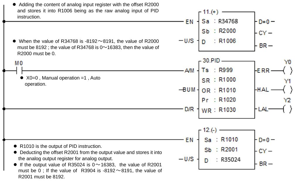
R999 :The setting of solution interval between calculations; for example the content of R999 is 200, it means it will perform this PID operation every 2 seconds.

R1000 :Scaled process variable, which is the engineering unit loaded by the PID instruction every time it gets solved. A linear scaling is done on R1006 using the high and low engineering range found in R1004 and R1005.

R1001 :Setpoint, it is the desired value the loop should control at; which is entered in engineering unit. For example the span of controlling process is 0°C~500°C, the setting of R1001 is equal to 100, it means the desired result is at 100°C.

R1002 :The setting of high alarm limit; which is entered in engineering unit.
The example mentioned above, if the setting of R1002 is equal to 105, it means there will have the high alarm while the loop is greater than or equal to 105°C.

R1003 :The setting of low alarm limit; which is entered in engineering unit. The example mentioned, if the setting of R1003 is equal to 95, it means there will have the low alarm while the loop is less than or equal to 95°C.

R1004 :The setting of high engineering range. The example mentioned, if the setting of R1004 is equal to 500, it means the highest value of this loop is 500°C.

R1005 :The setting of low engineering range. The example mentioned, if the setting of R1005 is equal to 0, it means the lowest value of this loop is 0°C.

R1006 :Raw analog measurement; it is the value that the content of analog input register (R34768〜R34895) is added by the offset of 2048.

R1007:Offset of process variable; let it be 0 if the raw analog signal and the span of the analog input module are all 0〜10V.

R1020 :The setting of proportional band; for example the content of R1020 is 20,
it means the proportional band is 2.0% and the gain is 50.

R1021 :The setting of integral tuning constant;
for example the content of R1021 is 17,
it means the reset time is 6 minutes
(100/6≒17).

R1022 :The setting of derivative tuning constant; for example the content of R1022 is 0, it means PI control.

R1023 :The setting of the bias to the output;
most applications let it be 0.

R1024 :The setting of high integral wind-up;
most applications let it be 16383.

R1025 :The setting of low integral wind-up;
most applications let it be 0.

R1026 :The setting of PID method;
most applications let it be 0.

R1030 = Loop status register

Bit0 =0, Manual operation mode
=1, Auto operation mode

Bit1 : This bit will be a 1 during the scan the solution is being solved, and it is ON for
a scan time.

Bit2=1 , Bumpless transfer

Bit4 : The status of "ERR" indication

Bit5 : The status of "HAL" indication

Bit6 : The status of "LAL" indication

R1031~R1034: They are the working registers, please refer to the description of operand WR.

Was this page helpful?

Tip: press ← → to switch chapters, Ctrl+K to search