Chapter 2. Configuration of memory, single point (Digital) and Register in PLC
※※Being designed with very broad flexibility range, the M-Serial PLC allows the user to access ordinary register field (containing 34768 counts of words) by the indirect addressing method. However, it may easily lead to false data writing issues if the indirect addressing parameters are improperly used. When operated in the Read-only Register Field-ROR (containing 4096 counts of words), the M-Serial PLC does not allow the user to access the register by the indirect addressing method. If the user needs to create important parameter values, it is recommended that the ROR (Read-only Register) Field should be used in order to execute the desired reading and writing according to the respective program commands. The main purpose is to avoid the issues that may be generated due to the incorrect parameters required for the indirect addressing.
2-1 M PLC Memory Configuration
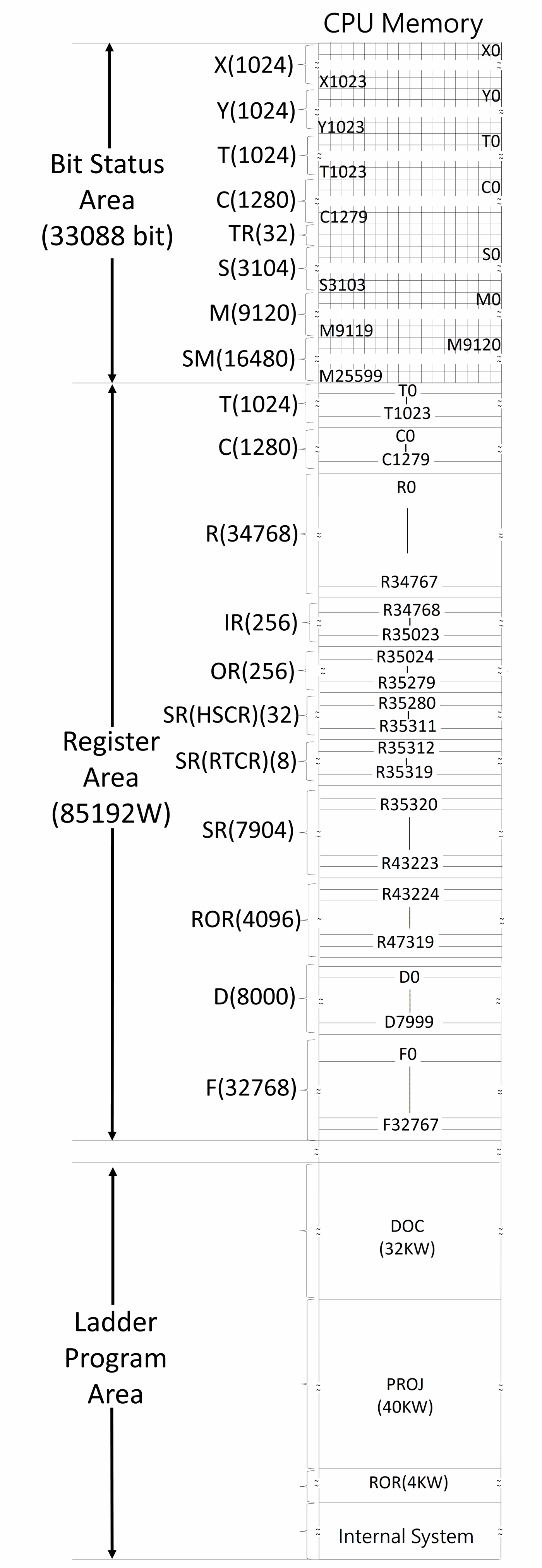
PLC memory configuration diagram
2-2 Digital and Register Configuration
This configuration is the factory setting:
|
Item |
Specifications |
Note |
||||
|
Single Point (BIT State) |
X |
Input contact (DI) (Max. point count: 2048 points) |
X0~X1023 (1024) |
Corresponding to external digital input |
||
|
Y |
Output relay (DO) (Max. point count: 2048 points) |
Y0~Y1023 (1024) |
Corresponding to external digital output |
|||
|
TR |
Temporary relay |
TR0~TR31(32) (Reserved for system operations) |
||||
|
M |
Internal |
M0~M9119 (9120) |
M0~M9119 can be configured as retentive or non-retentive relay. |
|||
|
Special Relay |
M9120~M25599 (16480) |
|||||
|
S |
Step Relay |
S0~S3103 (3104) |
S0~S3103 Can be configured as retentive or non-retentive relay. |
|||
|
T |
Timer "Time-Up" status contact |
T0~T1023 (1024) |
||||
|
C |
Counter "Counter-Up" status contact |
C0~C1279 (1280) |
||||
|
Register (WORD Data) Register (WORD Data) |
TMR |
Timer current value register |
0.001S Time Base |
T0~T255 (256) * |
T0~T1023 numbers for each time base can be adjusted. |
|
|
0.01S Time Base |
T256~T511 (256) * |
|||||
|
0.1S Time Base |
T512~T767 (256) * |
|||||
|
1S Time Base |
T768~T1023 (256) * |
|||||
|
CTR |
Counter current value register |
16-bit |
C0~C1023 (1024) |
Can be configured as non-retentive or retentive. |
||
|
32-bit |
C1024~C1279 (256) |
Can be configured as non-retentive or retentive. |
||||
|
HR DR |
Data Register |
Retentive |
R0~R14999 (15000) * Can be configured as non-retentive |
|||
|
Non-Retentive |
R15000~R34767 (19768) |
|||||
|
HR ROR |
Retentive |
R43224~R47319 (4096) * When not configured as ROR, it can serve normal register (for read/write) |
||||
|
Read Only Register (ROR) |
R43224~R47319 can be set as ROR ~ default setting is “0” * |
ROR is stored in special ROR area and not occupy program space |
||||
|
File Register |
F0~F65535(65536) * Save/retrieved via dedicated instruction |
|||||
|
IR |
Input Register (AI) |
R34768~R34895 (128) |
Corresponding to external analog input |
|||
|
OR |
Output Register (AO) |
R35024~R35151 (128) |
Corresponding to external analog output |
|||
|
SR |
Special System Register |
R35280~R43223 (7944) |
||||
|
〈Special Register〉 |
0.1ms HST Register |
R35451~R35466(16) |
|||||
|
1ms STM Register |
R35435~R35442(8) |
||||||
|
10ms LTM Register |
R35443~R35450(8) |
||||||
|
0.1ms HSTA Circulation Counter Register |
DR35467 |
||||||
|
High-Speed Counter Register |
R35280~R35311(32) |
||||||
|
Calendar Registers |
R35312 (Second) |
R35313 (Minute) |
R35314 (Hour) |
R35315 (Day) |
|||
|
R35316 (Month) |
R35317 (Year) |
R35318 (Week) |
R35319 (Hour+Minute) |
||||
|
FR |
File Register |
F0~F32767(32768) |
|||||
|
XR |
Index Register |
V: R43214 Z: R43216 P0~P9 : R43194, R43196, R43198, R43200, R43202, R43204, R43206, R43208, R43210, R43212 |
|||||
Digital and Register Configuration
Note: During power up or changing operation mode from STOP→RUN, all contents in non-retentive relays or registers will be cleared to 0; the retentive relays or registers will remain the same state as before.
2-3 CPU Special Relay Details
|
Relay No. |
Function/TAG Symbol |
Description |
|
|
1. Stop, Prohibit Control |
|||
|
M9120 |
Emergency Stop control EMERGENCY_STOP_CTRL |
If 1, PLC will be stopped. |
|
|
2. Disable, Clear Control |
|||
|
M9121 |
Reserve |
||
|
M9122 |
Disable Status Retent Select DISABLE_STATUS_RETENT_CTR |
Disabled when at 1 |
|
|
M9123 |
Clear Non-Retentive Relays CLR_NON_RETENT_RELAY |
Cleared when at 1 |
|
|
M9124 |
Clear Retentive Relays CLR_RETENT_RELAY |
Cleared when at 1 |
|
|
M9125 |
Clear Non-Retentive Registers CLR_NON_RETENT_REG |
Cleared when at 1 |
|
|
M9126 |
Clear Retentive Registers CLR_RETENT_REG |
Cleared when at 1 |
|
|
3. Pulse Signals |
||||
|
M9127 |
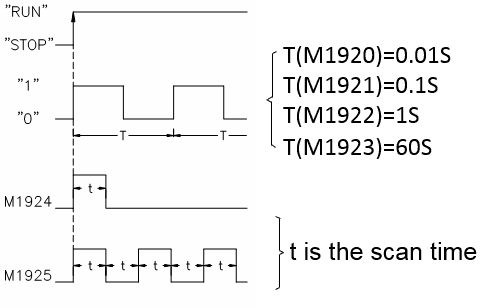
CLK_PULSE_0_01S
CLK_PULSE_0_1S 1 S Clock pulse CLK_PULSE_1S 60 S Clock pulse CLK_PULSE_60S |
|
||
|
M9218 |
||||
|
M9129 |
||||
|
M9130 |
||||
|
M9131 |
Initial Pulse (First Scan) CLK_PULSE_INIT Scan Cyclic Pulse ➂ CLK_PULSE_SCAN PLC Working Mode PLC_WORKING_MODE |
=0, PLC working at STOP Mode =1, PLC working at RUN Mode |
||
|
M9132 |
||||
|
M9133 |
||||
|
4. Error Messages |
||||
|
M9134 |
System Error Warning CPU_ABNL_WARNING |
1: Indicating no expansion unit or exceed the limit on number of I/O points |
||
|
5. Port1~Port2 Controls |
||||
|
M9135 |
Port1 Work Indicator COM_BUSY_P1 |
0: Port 1 Busy |
||
|
1: Port 1 Ready |
||||
|
M9136 |
Port 1 Work Indicator COM_DN_P1 |
1: Complete all communication transactions of FUN151 (CLINK), only one scan is ON. |
||
|
M9137 |
Port 1 Communication Status COM_STATUS_P1 |
Port 1 has received and transmitted a message |
||
|
M9138 |
Port 2 Work Indicator COM_BUSY_P2 |
0: Port 2 Busy 1: Port 2 Ready |
||
|
M9139 |
Port 2 Work Indicator COM_DN_P2 |
1: Complete all communication transactions of FUN151 (CLINK), only one scan is ON. |
||
|
M9140 |
Port 2 Communication Status COM_STATUS_P2 |
1: Port 2 has received and transmitted a message |
||
|
6. HSC0~HSC7 Controls |
||
|
M9141 |
HSC0 Software Mask HSC0_MSK |
1: Mask |
|
M9142 |
HSC0 Software Clear HSC0_CLR |
1: Clear |
|
M9143 |
HSC1 Software Mask HSC1_MSK |
1: Mask |
|
M9144 |
HSC1 Software Clear HSC1_CLR |
1: Clear |
|
M9145 |
HSC2 Software Mask HSC2_MSK |
1: Mask |
|
M9146 |
HSC2 Software Clear HSC2_CLR |
1: Clear |
|
M9147 |
HSC3 Software Mask HSC3_MSK |
1: Mask |
|
M9148 |
HSC3 Software Clear HSC3_CLR |
1: Clear |
|
M9149 |
Port3 Work Indicator(READY) |
|
|
M9150 |
Port3 Work Indicator(TABLE COMPLETE) |
|
|
M9151 |
Port3 Communication Status |
|
|
M9152 |
Port4 Work Indicator(READY) |
|
|
M9153 |
Port4 Work Indicator(TABLE COMPLETE) |
|
|
M9154 |
Port4 Communication Status |
|
|
M9155~ M9159 |
Reserved |
|
|
7. Communication/Timing/Counting Controls |
||
|
M9160 |
CAM Function Cross 0 Degree Selection CAM_FUNC_SELECT |
M9160=1: M9160=0: If among the upper and lower limit setting values, the upper limit value is less than the lower limit value, the limit value error flag The number "ERR" is set to 1, and the comparison output of this group is 0. |
|
M9161 |
High-Speed Pulse Output Stop Selection HSPSO_STOP_SELECT |
|
|
M9162 |
Update MODBUS Planning MODBUS_UPDATE |
|
|
M9163 |
Update COM Setting COM_UPDATE |
|
|
M9164 |
Reboot Network Interface ETH_UPDATE |
|
|
M9165 |
Enable DHCP ETH_DHCP_ENABLE |
|
|
M9166 |
1ms Timer STM 0 Control STM0_CTRL |
|
|
M9167 |
1ms Timer STM 1 Control STM1_CTRL |
|
|
M9168 |
1ms Timer STM 2 Control STM2_CTRL |
|
|
M9169 |
1ms Timer STM 3 Control STM3_CTRL |
|
|
M9170 |
10ms Timer LTM 0 Control LTM0_CTRL |
|
|
M9171 |
10ms Timer LTM 1 Control LTM1_CTRL |
|
|
M9172 |
10ms Timer LTM 2 Control LTM2_CTRL |
|
|
M9173 |
10ms Timer LTM 3 Control LTM3_CTRL |
|
|
M9174 |
0.1 ms HST 0 Control HST0_CTRL |
|
|
M9175 |
0.1ms HST 1 Control HST1_CTRL |
|
|
M9176 |
0.1ms HST 2 Control HST2_CTRL |
|
|
M9177 |
0.1ms HST 3 Control HST3_CTRL |
|
|
M9178 |
0.1ms HSTA Circulation Counter Control HSTA_CTRL |
|
|
8. RTC Control |
||
|
M9179 |
RTC Setting RTC_UPDATE |
|
|
M9180 |
30 S Adjustment RTC_30S_ADJUSTMENT |
|
|
M9181 |
RTC Installation Checking RTC_INSTALL_CHK |
|
|
M9182 |
Set Value Error RTC_SET_VALUE_ERROR |
|
|
9. PS0~7 Control |
||
|
M9183 |
PSO0 Indicator PSO0_BUSY |
|
|
M9184 |
PSO1 Indicator PSO1_BUSY |
|
|
M9185 |
PSO2 Indicator PSO2_BUSY |
|
|
M9186 |
PSO3 Indicator PSO3_BUSY |
|
|
M9187 |
PSO0 Done PSO0_DN |
|
|
M9188 |
PSO1 Done PSO1_DN |
|
|
M9189 |
PSO2 Done PSO2_DN |
|
|
M9190 |
PSO3 Done PSO3_DN |
|
|
M9191 |
PSO4 Indicator PSO4_BUSY |
|
|
M9192 |
PSO5 Indicator PSO5_BUSY |
|
|
M9193 |
PSO6 Indicator PSO6_BUSY |
|
|
M9194 |
PSO7 Indicator PSO7_BUSY |
|
|
M9195 |
PSO4 Done PSO4_DN |
|
|
M9196 |
PSO5 Done PSO5_DN |
|
|
M9197 |
PSO6 Done PSO6_DN |
|
|
M9198 |
PSO7 Done PSO7_DN |
|
|
10. Expansion Module Operation Field |
||
|
M9199~ M10511 |
Please refer to the respective Expansion Module User Manual. |
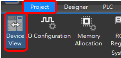
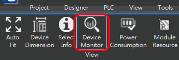
Because the number of special registers is related to the expansion module that will be set by the user, the sequence is not set with a fixed number order. Therefore, it will be learned through the following method: The number of Special Register can be displayed by clicking on the following profile: “Project-> Device View->Device Monitor ->select desired module.” The data indicated below are explained by using Data Buffer Relay as the example. The Data Buffer Relay will be started with the same method as the Triggering Data Buffer Relay.
|
|
M10512~ M16095 |
For Motion related special relays |
|
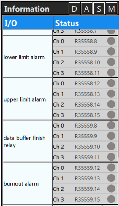
CPU Module special relay list
※All special relays do not provide Up/Down differential contact commands TU. If it is necessary to perform differential action on the special relay, it can be replaced by an indirect method. (Refer to the picture below)
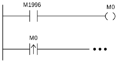
Differential Action Connection of Special Relay
|
Note: All special relays or registers attached with “◤” symbol shown in the above table are write prohibited. At the same time, this type of relay still prohibits/disables control and mandatory setting, and does not provide TU and TD contacts. |
2-4 CPU Special Registers Details
|
Register No./ System Tag Code |
Function/System Tag Symbol |
Description |
|---|---|---|
|
R35280 |
HSC0 current value Low word HSC0_CV |
|
|
R35281 |
HSC0 current value High word HSC0_CV |
|
|
R35282 |
HSC0 preset value Low word HSC0_PV |
|
|
R35283 |
HSC0 preset value High word HSC0_PV |
|
|
R35284 |
HSC1 current value Low word HSC1_CV |
|
|
R35285 |
HSC1 current value High word HSC1_CV |
|
|
R35286 |
HSC1 preset value Low word HSC1_PV |
|
|
R35287 |
HSC1 preset value High word HSC1_PV |
|
|
R35288 |
HSC2 current value Low word HSC2_CV |
|
|
R35289 |
HSC2 current value High word HSC2_CV |
|
|
R35290 |
HSC2 preset value Low word HSC2_PV |
|
|
R35291 |
HSC2 preset value High word HSC2_PV |
|
|
R35292 |
HSC3 current value Low word HSC3_CV |
|
|
R35293 |
HSC3 current value High word HSC3_CV |
|
|
R35294 |
HSC3 preset value Low word HSC3_PV |
|
|
R35295 |
HSC3 preset value High word HSC3_PV |
|
Register No./ System Tag Code |
Function/System Tag Symbol |
Description |
|---|---|---|
|
R35296 |
HSC4 current value Low word HSC4_CV |
|
|
R35297 |
HSC4 current value High word HSC4_CV |
|
|
R35298 |
Reserved |
|
|
R35299 |
Reserved |
|
|
R35300 |
HSC5 current value Low word HSC5_CV |
|
|
R35301 |
HSC5 current value High word HSC5_CV |
|
|
R35302 |
Reserved |
|
|
R35303 |
Reserved |
|
|
R35304 |
HSC6 current value Low word HSC6_CV |
|
|
R35305 |
HSC6 current value High word HSC6_CV |
|
|
R35306 |
Reserved |
|
|
R35307 |
Reserved |
|
|
R35308 |
HSC7 current value Low word HSC7_CV |
|
|
R35309 |
HSC7 current value High word HSC7_CV |
|
|
R35310 |
Reserved |
|
|
R35311 |
Reserved |
|
|
R35312 |
Second of calendar RTC_SECOND |
|
|
R35313 |
Minute of RTC RTC_MINUTE |
|
|
R35314 |
Hour of RTC RTC_HOUR |
|
|
R35315 |
Date of RTC RTC_DAY |
|
|
R35316 |
Month of RTC RTC_MONTH |
|
|
R35317 |
Year of RTC RTC_YEAR |
|
|
R35318 |
Week of RTC RTC_DAY_OF_WEEK |
|
|
R35319 |
Hour (High byte) + Minute (Low byte) RTC_HOUR_MINUTE |
|
|
R35320 |
Error code of PSO0 PSO0_ERR_CODE |
|
|
R35321 |
Error code of PSO1 PSO1_ERR_CODE |
|
|
R35322 |
Error code of PSO2 PSO2_ERR_CODE |
|
|
R35323 |
Error code of PSO3 PSO3_ERR_CODE |
|
|
R35324 |
Completed step number of positioning program for PSO0 PSO0_DN_STEP_NUM |
|
|
R35325 |
Completed step number of positioning program for PSO1 PSO1_DN_STEP_NUM |
|
|
R35326 |
Completed step number of positioning program for PSO2 PSO2_DN_STEP_NUM |
|
R35327 |
Completed step number of positioning program for PSO3 PSO3_DN_STEP_NUM |
|
|---|---|---|
|
R35328 |
Output frequency for Low Word of PSO0 PSO0_CUR_FREQ |
– |
|
R35329 |
Output frequency for High Word of PSO0 PSO0_CUR_FREQ |
– |
|
R35330 |
Output frequency for Low Word of PSO1 PSO1_CUR_FREQ |
– |
|
R35331 |
Output frequency for High Word of PSO1 PSO1_CUR_FREQ |
– |
|
R35332 |
Output frequency for Low Word of PSO2 PSO2_CUR_FREQ |
– |
|
R35333 |
Output frequency for High Word of PSO2 PSO2_CUR_FREQ |
– |
|
R35334 |
Output frequency for Low Word of PSO3 PSO3_CUR_FREQ |
– |
|
R35335 |
Output frequency for High Word of PSO3 PSO3_CUR_FREQ |
– |
|
R35336 |
Current pulse position for Low Word of PSO0 PSO0_CUR_POS |
|
|
R35337 |
Current pulse position for High Word of PSO0 PSO0_CUR_POS |
|
R35338 |
Current pulse position for Low Word of PSO1 PSO1_CUR_POS |
|
|---|---|---|
|
R35339 |
Current pulse position for High Word of PSO1 PSO1_CUR_POS |
|
|
R35340 |
Current pulse position for Low Word of PSO2 PSO2_CUR_POS |
|
|
R35341 |
Current pulse position for High Word of PSO2 PSO2_CUR_POS |
|
|
R35342 |
Current pulse position for Low Word of PSO3 PSO3_CUR_POS |
|
|
R35343 |
Current pulse position for High Word of PSO3 PSO3_CUR_POS |
|
|
R35344 |
Pulse count remaining for output for Low Word of PSO0 PSO0_REMAINING_COUNT |
|
|
R35345 |
Pulse count remaining for output for High Word of PSO0 PSO0_REMAINING_COUNT |
|
|
R35346 |
Pulse count remaining for output for Low Word of PSO1 PSO1_REMAINING_COUNT |
|
|
R35347 |
Pulse count remaining for output for High Word of PSO1 PSO1_REMAINING_COUNT |
|
|
R35348 |
Pulse count remaining for output for Low Word of PSO2 PSO2_REMAINING_COUNT |
|
R35349 |
Pulse count remaining for output for High Word of PSO2 PSO2_REMAINING_COUNT |
|
|---|---|---|
|
R35350 |
Pulse count remaining for output for Low Word of PSO3 PSO3_REMAINING_COUNT |
|
|
R35351 |
Pulse count remaining for output for High Word of PSO3 PSO3_REMAINING_COUNT |
|
|
R35352 |
COM1 Communication Parameters Setting COM_PARAM_P1 |
Set Baud Rate, Data bit… of Port 1 |
|
R35353 |
COM2 Communication Parameters Setting COM_PARAM_P2 |
Set Baud Rate, Data bit… of Port 2 |
|
R35354 |
COM1 & COM2 connection setting COM_STN_CHK_P1 COM_STN_CHK_P2 |
|
|
R35355 |
Communication protocol setting for COM1 and COM2 COM_PROTOCOL |
Set Port1 and Port2 as the FATEK or Modbus RTU/ASCII communication protocol |
||||||||||||||||||||||||||||||||||||||||||||||||||||||||||||||||||||
|---|---|---|---|---|---|---|---|---|---|---|---|---|---|---|---|---|---|---|---|---|---|---|---|---|---|---|---|---|---|---|---|---|---|---|---|---|---|---|---|---|---|---|---|---|---|---|---|---|---|---|---|---|---|---|---|---|---|---|---|---|---|---|---|---|---|---|---|---|---|---|
|
R35356 |
Reply delay time settings for COM 1 and COM2 |
|||||||||||||||||||||||||||||||||||||||||||||||||||||||||||||||||||||
|
R35357 |
Transmission delay and reception error detection time setting when COM1 is used as the master station COM_TX_DELAY_P1 |
|||||||||||||||||||||||||||||||||||||||||||||||||||||||||||||||||||||
|
R35358 |
Transmission delay and reception error detection time setting when COM2 is used as the master station COM_TX_DELAY_P2 |
|||||||||||||||||||||||||||||||||||||||||||||||||||||||||||||||||||||
|
R35359 |
Reserved |
|||||||||||||||||||||||||||||||||||||||||||||||||||||||||||||||||||||
|
R35360 |
System error indication (Need to confirm with LED) CPU_ERROR |
|
||||||||||||||||||||||||||||||||||||||||||||||||||||||||||||||||||||
|
R35361 ~R35362 |
CPU Status Indication CPU_STATUS |
BIT0: CPU RUN or Stop BIT1: Resvered BIT2: System Check Code Error BIT3: Memory Card Ready display BIT4: Watch-Dog Error BIT5: Motion Control Unit Detection BIT6: PLC ID Protection BIT7: Emergency Stop BIT8: Number of expansion module exceeds the scope BIT9: System STACK Error BIT10: Resvered BIT11: Function(s) existed that CPU does not support BIT12: Resvered BIT13: Resvered BIT14: RTC Ready Indicator BIT15: System Service Error Indicator BIT16: PLC ID Setting State BIT17: Program ID Setting State BIT18: Mian Program Password Setup State BIT19: Subroutine Password Setup State BIT20: PLC Upload Password Setup State BIT21: PLC Download Password Setup State BIT22: CIC Setup State BIT23: Resvered BIT24: Resvered BIT25~29: System Check Code Error Indicator BIT30: Switch State BIT31: Resvered |
||||||||||||||||||||||||||||||||||||||||||||||||||||||||||||||||||||
|
R35363 |
PLC station number display or setup PLC_STATION_NUM |
|
||||||||||||||||||||||||||||||||||||||||||||||||||||||||||||||||||||
|
R35364 |
PLC OS Version (MAJOR NO.) PLC_OS_VER_MAJOR |
|||||||||||||||||||||||||||||||||||||||||||||||||||||||||||||||||||||
|
R35365 |
PLC OS Version (MINOR NO + PATCH NO) PLC_OS_VER_MINOR PLC_OS_VER_PATCH |
|||||||||||||||||||||||||||||||||||||||||||||||||||||||||||||||||||||
|
R35366 |
Host model information (UNIT ID + MODEL) MAIN_UNIT_MODEL |
|||||||||||||||||||||||||||||||||||||||||||||||||||||||||||||||||||||
|
R35367 |
Power ON Delay (0.01s unit) POWER_ON_DELAY |
|
||||||||||||||||||||||||||||||||||||||||||||||||||||||||||||||||||||
|
R35368 |
Power Off Counter POWER_OFF_COUNTER |
|||||||||||||||||||||||||||||||||||||||||||||||||||||||||||||||||||||
|
R35369 |
Reserved |
|||||||||||||||||||||||||||||||||||||||||||||||||||||||||||||||||||||
|
R35370 |
Current Scan Time SCAN_TIME_CURRENT |
|
||||||||||||||||||||||||||||||||||||||||||||||||||||||||||||||||||||
|
R35371 |
Maximum Scan Time SCAN_TIME_MAX |
|||||||||||||||||||||||||||||||||||||||||||||||||||||||||||||||||||||
|
R35372 |
Minimum scan time SCAN_TIME_MIN |
|||||||||||||||||||||||||||||||||||||||||||||||||||||||||||||||||||||
|
R35373 |
Fixed Scan Time SCAN_TIME_SETTING |
– |
||||||||||||||||||||||||||||||||||||||||||||||||||||||||||||||||||||
|
R35374 |
Expansion Module Heart Beat Detection (Rack 1) EXP_HEARTBEAT_RACK1 |
|||||||||||||||||||||||||||||||||||||||||||||||||||||||||||||||||||||
|
R35375 |
Expansion Module Heart Beat Detection (Rack 2) EXP_HEARTBEAT_RACK2 |
|||||||||||||||||||||||||||||||||||||||||||||||||||||||||||||||||||||
|
R35376 |
Expansion Module Heart Beat Detection (Rack 3) EXP_HEARTBEAT_RACK3 |
|||||||||||||||||||||||||||||||||||||||||||||||||||||||||||||||||||||
|
R35377 |
Expansion Module Heart Beat Detection (Rack 4) EXP_HEARTBEAT_RACK4 |
|||||||||||||||||||||||||||||||||||||||||||||||||||||||||||||||||||||
|
R35378 |
Number of expansion AI points EXP_AI_POINTS |
|||||||||||||||||||||||||||||||||||||||||||||||||||||||||||||||||||||
|
R35379 |
Number of expansion AO points EXP_AO_POINTS |
|||||||||||||||||||||||||||||||||||||||||||||||||||||||||||||||||||||
|
R35380 |
Number of expansion DI points EXP_DI_POINTS |
|||||||||||||||||||||||||||||||||||||||||||||||||||||||||||||||||||||
|
R35381 |
Number of expansion DO points EXP_DO_POINTS |
|||||||||||||||||||||||||||||||||||||||||||||||||||||||||||||||||||||
|
R35382 |
CPU Ethernet Port IP Address OCT1 (Leading) ETH_IP_OCT1 |
– |
||||||||||||||||||||||||||||||||||||||||||||||||||||||||||||||||||||
|
R35383 |
CPU Ethernet Port IP Address OCT2 ETH_IP_OCT2 |
|||||||||||||||||||||||||||||||||||||||||||||||||||||||||||||||||||||
|
R35384 |
CPU Ethernet Port IP Address OCT3 ETH_IP_OCT3 |
|||||||||||||||||||||||||||||||||||||||||||||||||||||||||||||||||||||
|
R35385 |
CPU Ethernet Port IP Address OCT4 ETH_IP_OCT4 |
|||||||||||||||||||||||||||||||||||||||||||||||||||||||||||||||||||||
|
R35386 |
CPU Ethernet Port Mask OCT1 (Leading) ETH_SUBMASK_OCT1 |
|||||||||||||||||||||||||||||||||||||||||||||||||||||||||||||||||||||
|
R35387 |
CPU Ethernet Port Mask OCT2 ETH_SUBMASK_OCT2 |
|||||||||||||||||||||||||||||||||||||||||||||||||||||||||||||||||||||
|
R35388 |
CPU Ethernet Port Mask OCT3 ETH_SUBMASK_OCT3 |
|||||||||||||||||||||||||||||||||||||||||||||||||||||||||||||||||||||
|
R35389 |
CPU Ethernet Port Mask OCT4 ETH_SUBMASK_OCT4 |
|||||||||||||||||||||||||||||||||||||||||||||||||||||||||||||||||||||
|
R35390 |
CPU Ethernet Port Router OCT1 (Leading) ETH_GATEWAY_OCT1 |
|||||||||||||||||||||||||||||||||||||||||||||||||||||||||||||||||||||
|
R35391 |
CPU Ethernet Port Router OCT2 ETH_GATEWAY_OCT2 |
|||||||||||||||||||||||||||||||||||||||||||||||||||||||||||||||||||||
|
R35392 |
CPU Ethernet Port Router OCT3 ETH_GATEWAY_OCT3 |
|||||||||||||||||||||||||||||||||||||||||||||||||||||||||||||||||||||
|
R35393 |
CPU Ethernet Port Router OCT4 ETH_GATEWAY_OCT4 |
|||||||||||||||||||||||||||||||||||||||||||||||||||||||||||||||||||||
|
R35394 |
CPU Ethernet Primary DNS OCT1 (Leading) ETH_PRIM_DNS_OCT1 |
|||||||||||||||||||||||||||||||||||||||||||||||||||||||||||||||||||||
|
R35395 |
CPU Ethernet Primary DNS OCT2 ETH_PRIM_DNS_OCT2 |
|||||||||||||||||||||||||||||||||||||||||||||||||||||||||||||||||||||
|
R35396 |
CPU Ethernet Primary DNS OCT3 ETH_PRIM_DNS_OCT3 |
|||||||||||||||||||||||||||||||||||||||||||||||||||||||||||||||||||||
|
R35397 |
CPU Ethernet Primary DNS OCT4 ETH_PRIM_DNS_OCT4 |
|||||||||||||||||||||||||||||||||||||||||||||||||||||||||||||||||||||
|
R35398 |
CPU Ethernet Secondary DNS OCT1(Leading) ETH_SEC_DNS_OCT1 |
|||||||||||||||||||||||||||||||||||||||||||||||||||||||||||||||||||||
|
R35399 |
CPU Ethernet Secondary DNS OCT2 ETH_SEC_DNS_OCT2 |
|||||||||||||||||||||||||||||||||||||||||||||||||||||||||||||||||||||
|
R35400 |
CPU Ethernet Secondary DNS OCT3 ETH_SEC_DNS_OCT3 |
|||||||||||||||||||||||||||||||||||||||||||||||||||||||||||||||||||||
|
R35401 |
CPU Ethernet Secondary DNS OCT4 ETH_SEC_DNS_OCT4 |
|||||||||||||||||||||||||||||||||||||||||||||||||||||||||||||||||||||
|
R35402 |
Modbus: Y Starting Address MODBUS_COIL_ADDR_Y |
|||||||||||||||||||||||||||||||||||||||||||||||||||||||||||||||||||||
|
R35403 |
Modbus: Coil Starting Address MODBUS_COIL_Y |
|||||||||||||||||||||||||||||||||||||||||||||||||||||||||||||||||||||
|
R35404 |
Modbus: Corresponding Length MODBUS_ COIL_TOTALS_Y |
|||||||||||||||||||||||||||||||||||||||||||||||||||||||||||||||||||||
|
R35405 |
Modbus: X Starting Address MODBUS_ COIL_ADDR_X |
|||||||||||||||||||||||||||||||||||||||||||||||||||||||||||||||||||||
|
R35406 |
Modbus: Coil Starting Address MODBUS_COIL_X |
|||||||||||||||||||||||||||||||||||||||||||||||||||||||||||||||||||||
|
R35407 |
Modbus: Corresponding Length MODBUS_ COIL_TOTALS_X |
|||||||||||||||||||||||||||||||||||||||||||||||||||||||||||||||||||||
|
R35408 |
Modbus: M Starting Address MODBUS_ COIL_ADDR_M |
|||||||||||||||||||||||||||||||||||||||||||||||||||||||||||||||||||||
|
R35409 |
Modbus: Coil Starting Address MODBUS_COIL_M |
|||||||||||||||||||||||||||||||||||||||||||||||||||||||||||||||||||||
|
R35410 |
Modbus: Corresponding Length MODBUS_ COIL_TOTALS_M |
|||||||||||||||||||||||||||||||||||||||||||||||||||||||||||||||||||||
|
R35411 |
Modbus: S Starting Address MODBUS_ COIL_ADDR_S |
|||||||||||||||||||||||||||||||||||||||||||||||||||||||||||||||||||||
|
R35412 |
Modbus: Coil Starting Address MODBUS_COIL_S |
|||||||||||||||||||||||||||||||||||||||||||||||||||||||||||||||||||||
|
R35413 |
Modbus: Corresponding Length MODBUS_ COIL_TOTALS_S |
|||||||||||||||||||||||||||||||||||||||||||||||||||||||||||||||||||||
|
R35414 |
Modbus: T starting address MODBUS_ COIL_ADDR_T |
|||||||||||||||||||||||||||||||||||||||||||||||||||||||||||||||||||||
|
R35415 |
Modbus: Coil Starting Address MODBUS_COIL_T |
|||||||||||||||||||||||||||||||||||||||||||||||||||||||||||||||||||||
|
R35416 |
Modbus: Corresponding Length MODBUS_ COIL_TOTALS_T |
|||||||||||||||||||||||||||||||||||||||||||||||||||||||||||||||||||||
|
R35417 |
Modbus: C Starting Address MODBUS_ COIL_ADDR_C |
|||||||||||||||||||||||||||||||||||||||||||||||||||||||||||||||||||||
|
R35418 |
Modbus: Coil Starting Address MODBUS_COIL_C |
|||||||||||||||||||||||||||||||||||||||||||||||||||||||||||||||||||||
|
R35419 |
Modbus: Corresponding Length MODBUS_ COIL_TOTALS_C |
|||||||||||||||||||||||||||||||||||||||||||||||||||||||||||||||||||||
|
R35420 |
Modbus: R Starting Address MODBUS _HOLDING_ADDR_R |
|||||||||||||||||||||||||||||||||||||||||||||||||||||||||||||||||||||
|
R35421 |
Modbus: Holding Starting Address MODBUS_HOLDING_R |
|||||||||||||||||||||||||||||||||||||||||||||||||||||||||||||||||||||
|
R35422 |
Modbus: Corresponding Length MODBUS_HOLDING _TOTALS_R |
|||||||||||||||||||||||||||||||||||||||||||||||||||||||||||||||||||||
|
R35423 |
Modbus: D Starting Address MODBUS _HOLDING_ADDR_D |
|||||||||||||||||||||||||||||||||||||||||||||||||||||||||||||||||||||
|
R35424 |
Modbus: Holding Starting Address MODBUS_HOLDING_D |
|||||||||||||||||||||||||||||||||||||||||||||||||||||||||||||||||||||
|
R35425 |
Modbus: Corresponding Length MODBUS _HOLDING_TOTALS_D |
|||||||||||||||||||||||||||||||||||||||||||||||||||||||||||||||||||||
|
R35426 |
Modbus: RT Starting Address MODBUS _HOLDING_ADDR_RT |
|||||||||||||||||||||||||||||||||||||||||||||||||||||||||||||||||||||
|
R35427 |
Modbus: Holding Starting Address MODBUS_HOLDING_RT |
|||||||||||||||||||||||||||||||||||||||||||||||||||||||||||||||||||||
|
R35428 |
Modbus: Corresponding Length MODBUS _HOLDING_TOTALS_RT |
|||||||||||||||||||||||||||||||||||||||||||||||||||||||||||||||||||||
|
R35429 |
Modbus: RC Starting Address MODBUS _HOLDING_ADDR_RC |
|||||||||||||||||||||||||||||||||||||||||||||||||||||||||||||||||||||
|
R35430 |
Modbus: Holding Starting Address MODBUS_HOLDING_RC |
|||||||||||||||||||||||||||||||||||||||||||||||||||||||||||||||||||||
|
R35431 |
Modbus: Corresponding Length MODBUS _HOLDING_TOTALS_RC |
|||||||||||||||||||||||||||||||||||||||||||||||||||||||||||||||||||||
|
R35432 |
Modbus: LC Starting Address MODBUS _HOLDING_ADDR_DRC |
|||||||||||||||||||||||||||||||||||||||||||||||||||||||||||||||||||||
|
R35433 |
Modbus: Holding Starting Address MODBUS_HOLDING_DRC |
|||||||||||||||||||||||||||||||||||||||||||||||||||||||||||||||||||||
|
R35434 |
Modbus: Corresponding Length MODBUS _HOLDING_TOTALS_DRC |
|||||||||||||||||||||||||||||||||||||||||||||||||||||||||||||||||||||
|
R35435 |
1ms Timer STM 0 Cycle Setting STM0_PV |
|||||||||||||||||||||||||||||||||||||||||||||||||||||||||||||||||||||
|
R35436 |
1ms Timer STM 0 Current Time STM0_CV |
|||||||||||||||||||||||||||||||||||||||||||||||||||||||||||||||||||||
|
R35437 |
1ms Timer STM 1 Cycle Setting STM1_PV |
|||||||||||||||||||||||||||||||||||||||||||||||||||||||||||||||||||||
|
R35438 |
1ms Timer STM 1 Current Time STM1_CV |
|||||||||||||||||||||||||||||||||||||||||||||||||||||||||||||||||||||
|
R35439 |
1ms Timer STM 2 Cycle Setting STM2_PV |
|||||||||||||||||||||||||||||||||||||||||||||||||||||||||||||||||||||
|
R35440 |
1ms Timer STM 2 Current Time STM2_CV |
|||||||||||||||||||||||||||||||||||||||||||||||||||||||||||||||||||||
|
R35441 |
1ms Timer STM 3 Cycle Setting STM3_PV |
|||||||||||||||||||||||||||||||||||||||||||||||||||||||||||||||||||||
|
R35442 |
1ms Timer STM 3 Current Time STM3_CV |
|||||||||||||||||||||||||||||||||||||||||||||||||||||||||||||||||||||
|
R35443 |
10 ms Timer STM 0 Cycle Setting LTM0_PV |
|||||||||||||||||||||||||||||||||||||||||||||||||||||||||||||||||||||
|
R35444 |
10 msTimer STM 0 Current Time LTM0_CV |
|||||||||||||||||||||||||||||||||||||||||||||||||||||||||||||||||||||
|
R35445 |
10 ms Timer STM 1 Cycle Setting LTM1_PV |
|||||||||||||||||||||||||||||||||||||||||||||||||||||||||||||||||||||
|
R35446 |
10 msTimer STM 1 Current Time LTM1_CV |
|||||||||||||||||||||||||||||||||||||||||||||||||||||||||||||||||||||
|
R35447 |
10 ms Timer STM 2 Cycle Setting LTM2_PV |
|||||||||||||||||||||||||||||||||||||||||||||||||||||||||||||||||||||
|
R35448 |
10 msTimer STM 2 Current Time LTM2_CV |
|||||||||||||||||||||||||||||||||||||||||||||||||||||||||||||||||||||
|
R35449 |
10 ms Timer STM 3 Cycle Setting LTM3_PV |
|||||||||||||||||||||||||||||||||||||||||||||||||||||||||||||||||||||
|
R35450 |
10 msTimer STM 3 Current Time LTM3_CV |
|||||||||||||||||||||||||||||||||||||||||||||||||||||||||||||||||||||
|
R35451 |
0.1ms Timer HST 0 Cycle Setting LOW WORD HST0_PV |
|||||||||||||||||||||||||||||||||||||||||||||||||||||||||||||||||||||
|
R35452 |
0.1ms Timer HST 0 Cycle Setting HIGH WORD HST0_PV |
|||||||||||||||||||||||||||||||||||||||||||||||||||||||||||||||||||||
|
R35453 |
0.1ms Timer HST 0 Current Time LOW WORD HST0_CV |
|||||||||||||||||||||||||||||||||||||||||||||||||||||||||||||||||||||
|
R35454 |
0.1ms Timer HST 0 Current Time HIGH WORD HST0_CV |
|||||||||||||||||||||||||||||||||||||||||||||||||||||||||||||||||||||
|
R35455 |
0.1ms Timer HST 1 Cycle Setting LOW WORD HST1_PV |
|||||||||||||||||||||||||||||||||||||||||||||||||||||||||||||||||||||
|
R35456 |
0.1ms Timer HST 1 Cycle Setting HIGH WORD HST1_PV |
|||||||||||||||||||||||||||||||||||||||||||||||||||||||||||||||||||||
|
R35457 |
0.1ms Timer HST 1 Current Time LOW WORD HST1_CV |
|||||||||||||||||||||||||||||||||||||||||||||||||||||||||||||||||||||
|
R35458 |
0.1ms Timer HST 1 Current Time HIGH WORD HST1_CV |
|||||||||||||||||||||||||||||||||||||||||||||||||||||||||||||||||||||
|
R35459 |
0.1ms Timer HST 2 Cycle Setting LOW WORD HST2_PV |
|||||||||||||||||||||||||||||||||||||||||||||||||||||||||||||||||||||
|
R35460 |
0.1ms Timer HST 2 Cycle Setting HIGH WORD HST2_PV |
|||||||||||||||||||||||||||||||||||||||||||||||||||||||||||||||||||||
|
R35461 |
0.1ms Timer HST 2 Current Time LOW WORD HST2_CV |
|||||||||||||||||||||||||||||||||||||||||||||||||||||||||||||||||||||
|
R35462 |
0.1ms Timer HST 2 Current Time HIGH WORD HST2_CV |
|||||||||||||||||||||||||||||||||||||||||||||||||||||||||||||||||||||
|
R35463 |
0.1ms Timer HST 3 Cycle Setting LOW WORD HST3_PV |
|||||||||||||||||||||||||||||||||||||||||||||||||||||||||||||||||||||
|
R35464 |
0.1ms Timer HST 3 Cycle Setting HIGH WORD HST3_PV |
|||||||||||||||||||||||||||||||||||||||||||||||||||||||||||||||||||||
|
R35465 |
0.1ms Timer HST 3 Current Time LOW WORD HST3_CV |
|||||||||||||||||||||||||||||||||||||||||||||||||||||||||||||||||||||
|
R35466 |
0.1ms Timer HST 3 Current Time HIGH WORD HST3_CV |
|||||||||||||||||||||||||||||||||||||||||||||||||||||||||||||||||||||
|
R35467 |
0.1ms HSTA HSTA Current Count LOW WORD HSTA_CV |
|||||||||||||||||||||||||||||||||||||||||||||||||||||||||||||||||||||
|
R35468 |
0.1ms HSTA HSTA Current Count HIGH WORD HSTA_CV |
|||||||||||||||||||||||||||||||||||||||||||||||||||||||||||||||||||||
|
R35469- R35478 |
It is used for designating the Data Register that should be replicated in the SD Card for reading, and the user needs to create such field before replicating the SD Card. After turning on the PC, it will execute the required action according to SR18~SR27 that have been replicated in the SD Card. SD_GROUP_FLAG SD_GROUP_COUNT SD_GROUP_LEN1 SD_GROUP_ADDR1 SD_GROUP_LEN2 SD_GROUP_ADDR2 SD_GROUP_LEN3 SD_GROUP_ADDR3 SD_GROUP_LEN4 SD_GROUP_ADDR4 |
When using ROM Pack to save the Ladder program and the data register, this table should be used to determine the registers that should be replicated. When turning on the PC, it will be read by ROM Pack for executing the required initialization procedure. |
||||||||||||||||||||||||||||||||||||||||||||||||||||||||||||||||||||
|
R35479 |
Control the register to be read by SD Card. Determine if the data register in the PACK should be read when turning on the PC. SD_GROUP_LOAD_FLAG |
=5530H: When turning on the PC, it will not read the data register that has been replicated to ROM Pack. = Other value: When turning on the PC, the content of the data register being replicated to ROM Pack will be initialized as the value when the register is replicated. |
||||||||||||||||||||||||||||||||||||||||||||||||||||||||||||||||||||
|
R35480 |
Test-run modification mode or replicate the SD Card related command and the state SD_STATE |
|||||||||||||||||||||||||||||||||||||||||||||||||||||||||||||||||||||
|
R35481 |
User-defined TCP port of Fatek binary server ETH_FATEK_CUSTOM_PORT |
|||||||||||||||||||||||||||||||||||||||||||||||||||||||||||||||||||||
|
R35482 |
User-defined TCP port of Modbus TCP server ETH_MODBUS_CUSTOM_PORT |
|||||||||||||||||||||||||||||||||||||||||||||||||||||||||||||||||||||
|
R35483 |
iMonitor Connection Status IMONITOR_STATUS |
0: Offline 1: Online 2: Connecting Others: Error code |
||||||||||||||||||||||||||||||||||||||||||||||||||||||||||||||||||||
|
R35484- R35486 |
Host MAC address SYS_MAC1 SYS_MAC2 SYS_MAC3 |
|||||||||||||||||||||||||||||||||||||||||||||||||||||||||||||||||||||
|
R35487- R35643 |
Reserve |
|||||||||||||||||||||||||||||||||||||||||||||||||||||||||||||||||||||
|
R35644 |
SD Operation Information Word Group High byte: State Code Low byte: Operation Code SD_OPERATION_STATUS |
|||||||||||||||||||||||||||||||||||||||||||||||||||||||||||||||||||||
|
R35645 |
Build-in Analog Input Channel 0 Read Value (M2 Type) PLC_AI0 |
|||||||||||||||||||||||||||||||||||||||||||||||||||||||||||||||||||||
|
R35646 |
Build-in Analog Input Channel 1 Read Value (M2 Type) PLC_AI1 |
|||||||||||||||||||||||||||||||||||||||||||||||||||||||||||||||||||||
|
R35647 |
Error code of PSO 4 PSO4_ERR_CODE |
|||||||||||||||||||||||||||||||||||||||||||||||||||||||||||||||||||||
|
R35648 |
Error code of PSO 5 PSO5_ERR_CODE |
|||||||||||||||||||||||||||||||||||||||||||||||||||||||||||||||||||||
|
R35649 |
Error code of PSO 6 PSO6_ERR_CODE |
|||||||||||||||||||||||||||||||||||||||||||||||||||||||||||||||||||||
|
R35650 |
Error code of PSO 7 PSO7_ERR_CODE |
|||||||||||||||||||||||||||||||||||||||||||||||||||||||||||||||||||||
|
R35651 |
Completed step number of positioning program for PSO4 PSO4_DN_STEP_NUM |
|||||||||||||||||||||||||||||||||||||||||||||||||||||||||||||||||||||
|
R35652 |
Completed step number of positioning program for PSO5 PSO5_DN_STEP_NUM |
|||||||||||||||||||||||||||||||||||||||||||||||||||||||||||||||||||||
|
R35653 |
Completed step number of positioning program for PSO6 PSO6_DN_STEP_NUM |
|||||||||||||||||||||||||||||||||||||||||||||||||||||||||||||||||||||
|
R35654 |
Completed step number of positioning program for PSO7 PSO7_DN_STEP_NUM |
|||||||||||||||||||||||||||||||||||||||||||||||||||||||||||||||||||||
|
R35655 |
Output frequency for Low Word of PSO4 PSO4_CUR_FREQ |
|||||||||||||||||||||||||||||||||||||||||||||||||||||||||||||||||||||
|
R35656 |
Output frequency for High Word of PSO4 PSO4_CUR_FREQ |
|||||||||||||||||||||||||||||||||||||||||||||||||||||||||||||||||||||
|
R35657 |
Output frequency for Low Word of PSO5 PSO5_CUR_FREQ |
|||||||||||||||||||||||||||||||||||||||||||||||||||||||||||||||||||||
|
R35658 |
Output frequency for High Word of PSO5 PSO5_CUR_FREQ |
|||||||||||||||||||||||||||||||||||||||||||||||||||||||||||||||||||||
|
R35659 |
Output frequency for Low Word of PSO6 PSO6_CUR_FREQ |
|||||||||||||||||||||||||||||||||||||||||||||||||||||||||||||||||||||
|
R35660 |
Output frequency for High Word of PSO6 PSO6_CUR_FREQ |
|||||||||||||||||||||||||||||||||||||||||||||||||||||||||||||||||||||
|
R35661 |
Output frequency for Low Word of PSO7 PSO7_CUR_FREQ |
|||||||||||||||||||||||||||||||||||||||||||||||||||||||||||||||||||||
|
R35662 |
Output frequency for High Word of PSO7 PSO7_CUR_FREQ |
|||||||||||||||||||||||||||||||||||||||||||||||||||||||||||||||||||||
|
R35663 |
Current pulse position for Low Word of PSO4 PSO4_CUR_POS |
|||||||||||||||||||||||||||||||||||||||||||||||||||||||||||||||||||||
|
R35664 |
Current pulse position for High Word of PSO4 PSO4_CUR_POS |
|||||||||||||||||||||||||||||||||||||||||||||||||||||||||||||||||||||
|
R35665 |
Current pulse position for Low Word of PSO5 PSO5_CUR_POS |
|||||||||||||||||||||||||||||||||||||||||||||||||||||||||||||||||||||
|
R35666 |
Current pulse position for High Word of PSO5 PSO5_CUR_POS |
|||||||||||||||||||||||||||||||||||||||||||||||||||||||||||||||||||||
|
R35667 |
Current pulse position for Low Word of PSO6 PSO6_CUR_POS |
|||||||||||||||||||||||||||||||||||||||||||||||||||||||||||||||||||||
|
R35668 |
Current pulse position for High Word of PSO6 PSO6_CUR_POS |
|||||||||||||||||||||||||||||||||||||||||||||||||||||||||||||||||||||
|
R35669 |
Current pulse position for Low Word of PSO7 PSO7_CUR_POS |
|||||||||||||||||||||||||||||||||||||||||||||||||||||||||||||||||||||
|
R35670 |
Current pulse position for High Word of PSO7 PSO7_CUR_POS |
|||||||||||||||||||||||||||||||||||||||||||||||||||||||||||||||||||||
|
R35671 |
Pulse count remaining for output for Low Word of PSO4 PSO4_REMAINING_COUNT |
|||||||||||||||||||||||||||||||||||||||||||||||||||||||||||||||||||||
|
R35672 |
Pulse count remaining for output for High Word of PSO4 PSO4_REMAINING_COUNT |
|||||||||||||||||||||||||||||||||||||||||||||||||||||||||||||||||||||
|
R35673 |
Pulse count remaining for output for Low Word of PSO5 PSO5_REMAINING_COUNT |
|||||||||||||||||||||||||||||||||||||||||||||||||||||||||||||||||||||
|
R35674 |
Pulse count remaining for output for High Word of PSO5 PSO5_REMAINING_COUNT |
|||||||||||||||||||||||||||||||||||||||||||||||||||||||||||||||||||||
|
R35675 |
Pulse count remaining for output for Low Word of PSO6 PSO6_REMAINING_COUNT |
|||||||||||||||||||||||||||||||||||||||||||||||||||||||||||||||||||||
|
R35676 |
Pulse count remaining for output for High Word of PSO6 PSO6_REMAINING_COUNT |
|||||||||||||||||||||||||||||||||||||||||||||||||||||||||||||||||||||
|
R35677 |
Pulse count remaining for output for Low Word of PSO7 PSO7_REMAINING_COUNT |
|||||||||||||||||||||||||||||||||||||||||||||||||||||||||||||||||||||
|
R35678 |
Pulse count remaining for output for High Word of PSO7 PSO7_REMAINING_COUNT |
|||||||||||||||||||||||||||||||||||||||||||||||||||||||||||||||||||||
|
R35679 |
MQTT Connection Status MQTT_STATUS |
MQTT_CONNECT_ACCEPTED = 0, MQTT_CONNECT_REFUSED_PROTOCOL_VERSION = 1, MQTT_CONNECT_REFUSED_IDENTIFIER = 2, MQTT_CONNECT_REFUSED_SERVER = 3, MQTT_CONNECT_REFUSED_USERNAME_PASS = 4, MQTT_CONNECT_REFUSED_NOT_AUTHORIZED_ = 5, MQTT_CONNECT_DISCONNECTED = 256, MQTT_CONNECT_TIMEOUT = 257 MQTT_CONNECT_MEMORY_LACK = 258 |
||||||||||||||||||||||||||||||||||||||||||||||||||||||||||||||||||||
|
R35680~ R35760 |
Reserved |
|||||||||||||||||||||||||||||||||||||||||||||||||||||||||||||||||||||
|
R35761 |
Able to dynamically change the high-speed pulse output frequency HSPO_FREQ_CTRL |
|||||||||||||||||||||||||||||||||||||||||||||||||||||||||||||||||||||
|
R35762 |
COM2 high-speed network enable/mode |
Low Bit=55H, High-speed slave station enable =Others, Disabled High Bit=55H, High-speed master station communication with one-table cycle =Others, Continuous |
||||||||||||||||||||||||||||||||||||||||||||||||||||||||||||||||||||
|
R35763 |
COM2 Receive/Transmit Timeout Setting (High-Speed) COM_RX_TX_TIME_P2H |
When the value of the high byte is not 56H, the system will generate appropriate settings based on the communication parameters set in R4161, and the user does not need to configure them. When the value of the high byte is 56H, the low byte is reserved for manual settings when the system configuration does not meet the requirements of use.R4160[5-0] : Reserve R4160[7-6]:Set TX TMO, =0, 500us ; =1, 700us ; =2, 900us ; =3, 1100us M PLC high-speed communication Baud Rate and the automatic setting for Rx/Tx time out values is as follows: For reference: Baud Rate = 38400, Rx = 8 bit time , Tx = 700us Baud Rate = 153600, Rx = 16 bit time , Tx = 700us Baud Rate = 614400, Rx = 20 bit time , Tx = 700us |
||||||||||||||||||||||||||||||||||||||||||||||||||||||||||||||||||||
|
R35764 |
Type of FUN30 system analog value bit PID_AI_RESOLUTION |
=0, 12bit =1, 14bit =Other, Nbit |
||||||||||||||||||||||||||||||||||||||||||||||||||||||||||||||||||||
|
R35765 |
Gain constant of FUN30 PID_GAIN |
|||||||||||||||||||||||||||||||||||||||||||||||||||||||||||||||||||||
|
R35766 |
FUN147 Gp0 vector speed for Low Word |
|||||||||||||||||||||||||||||||||||||||||||||||||||||||||||||||||||||
|
R35767 |
FUN147 Gp0 vector speed for High Word |
|||||||||||||||||||||||||||||||||||||||||||||||||||||||||||||||||||||
|
R35768 |
FUN147 Gp1 vector speed for Low Word |
|||||||||||||||||||||||||||||||||||||||||||||||||||||||||||||||||||||
|
R35769 |
FUN147 Gp1 vector speed for High Word |
|||||||||||||||||||||||||||||||||||||||||||||||||||||||||||||||||||||
|
R35770 |
FUN147 Gp2 vector speed for Low Word |
|||||||||||||||||||||||||||||||||||||||||||||||||||||||||||||||||||||
|
R35771 |
FUN147 Gp2 vector speed for High Word |
|||||||||||||||||||||||||||||||||||||||||||||||||||||||||||||||||||||
|
R35772 |
FUN147 Gp3 vector speed for Low Word |
|||||||||||||||||||||||||||||||||||||||||||||||||||||||||||||||||||||
|
R35773 |
FUN147 Gp3 vector speed for High Word |
|||||||||||||||||||||||||||||||||||||||||||||||||||||||||||||||||||||
|
R35774 |
FUN147 Gp0 error code |
|||||||||||||||||||||||||||||||||||||||||||||||||||||||||||||||||||||
|
R35775 |
FUN147 Gp1 error code |
|||||||||||||||||||||||||||||||||||||||||||||||||||||||||||||||||||||
|
R35776 |
FUN147 Gp2 error code |
|||||||||||||||||||||||||||||||||||||||||||||||||||||||||||||||||||||
|
R35777 |
FUN147 Gp3 error code |
|||||||||||||||||||||||||||||||||||||||||||||||||||||||||||||||||||||
|
R35778 |
The step number (positioning point) which has been completed of FUN147 Gp0. |
|||||||||||||||||||||||||||||||||||||||||||||||||||||||||||||||||||||
|
R35779 |
The step number (positioning point) which has been completed of FUN147 Gp1. |
|||||||||||||||||||||||||||||||||||||||||||||||||||||||||||||||||||||
|
R35780 |
The step number (positioning point) which has been completed of FUN147 Gp2. |
|||||||||||||||||||||||||||||||||||||||||||||||||||||||||||||||||||||
|
R35781 |
The step number (positioning point) which has been completed of FUN147 Gp3. |
|||||||||||||||||||||||||||||||||||||||||||||||||||||||||||||||||||||
|
R35782~ R35797 |
Reserved |
|||||||||||||||||||||||||||||||||||||||||||||||||||||||||||||||||||||
|
R35798 |
COM3 Communication Parameters Setting |
|||||||||||||||||||||||||||||||||||||||||||||||||||||||||||||||||||||
|
R35799 |
COM4 Communication Parameters Setting |
|||||||||||||||||||||||||||||||||||||||||||||||||||||||||||||||||||||
|
R35800 |
COM3 and COM4 connection setting |
|||||||||||||||||||||||||||||||||||||||||||||||||||||||||||||||||||||
|
R35801 |
Communication protocol setting for COM3 and COM4 |
|||||||||||||||||||||||||||||||||||||||||||||||||||||||||||||||||||||
|
R35802 |
Reply delay time settings for COM3 and COM4 |
|||||||||||||||||||||||||||||||||||||||||||||||||||||||||||||||||||||
|
R35803 |
Transmission delay and reception error detection time setting when COM3 is used as the master station |
|||||||||||||||||||||||||||||||||||||||||||||||||||||||||||||||||||||
|
R35804 |
Transmission delay and reception error detection time setting when COM4 is used as the master station |
|||||||||||||||||||||||||||||||||||||||||||||||||||||||||||||||||||||
|
R35805~ R35821 |
Reserved |
|||||||||||||||||||||||||||||||||||||||||||||||||||||||||||||||||||||
|
R35822~ R35871 |
Expansion module calibration reserved registers |
|||||||||||||||||||||||||||||||||||||||||||||||||||||||||||||||||||||
|
R35872~ R36871 |
Starting register of expansion module status |
|||||||||||||||||||||||||||||||||||||||||||||||||||||||||||||||||||||
|
R36872~ R36879 |
TEST RUN Reserve Register (Read-Only) |
|||||||||||||||||||||||||||||||||||||||||||||||||||||||||||||||||||||
|
R36880~ R36979 |
For Motion related special Registers |
|||||||||||||||||||||||||||||||||||||||||||||||||||||||||||||||||||||
|
R36980- |
Motion axis data start (read-only) |
|||||||||||||||||||||||||||||||||||||||||||||||||||||||||||||||||||||
|
R43194~ R43213 |
P0 (R43194), Reserved(R43195), P1(R43196), Reserved(R43197), P2(R43198), … P9 (R43212), Reserved(R43213) INDEX_P0 INDEX_P1 INDEX_P2 INDEX_P3 INDEX_P4 INDEX_P5 INDEX_P6 INDEX_P7 INDEX_P8 INDEX_P9 |
|||||||||||||||||||||||||||||||||||||||||||||||||||||||||||||||||||||
|
R43214 |
V INDEX_V |
|||||||||||||||||||||||||||||||||||||||||||||||||||||||||||||||||||||
|
R43216 |
Z INDEX_Z |
|||||||||||||||||||||||||||||||||||||||||||||||||||||||||||||||||||||
2-5 Motion Special Relay Details
※ For more detailed information, please refer to MPLC Motion User Manual Chapter 2〝Motion Parameters and Status (Special Register and Relay)〞
※ The table lists the register numbers for axis 1, and for each subsequent axis, the register number is obtained by adding 40*(n-1), ‘n’ represents the axis number.
|
Relay No. |
Function |
System Tag Symbol |
|---|---|---|
|
M10520 |
All axes: Servo ON |
ALL_SERVO_ON |
|
M10521 |
All axes: Servo Reset |
ALL_SERVO_FAULT_RST |
|
M10522 |
Write all mapping parameters during initialization. |
MAPPING_ALL_PARM_AFTER_INIT |
|
M10523 |
Motion control card restart. |
RESTART_MOTION_CARD |
|
M10524 |
Custom PDO packet for special registers |
ENABLE_CUSTOM_PDO |
|
M10600 + 40*(n-1) |
Axis control command: Servo ON |
SERVO_ON |
|
M10601+ 40*(n-1) |
Axis control command: Fault Reset |
FAULT_RST |
|
M10602+ 40*(n-1) |
Axis control command: Deceleration Stop |
DEC_STOP |
|
M10603+ 40*(n-1) |
Axis control command: Emergency stop |
EMG_STOP |
|
M10604+ 40*(n-1) |
Axis Synchronous main clutch ON |
SYNC_MAIN_CLU_ON |
|
M10605+ 40*(n-1) |
Axis Origin On |
ORIG_SIG_IN |
|
M10606+ 40*(n-1) |
Axis limit(+) on |
LIM_POS_IN |
|
M10607+ 40*(n-1) |
Axis limit(-) on |
LIM_NEG_IN |
|
M10608+ 40*(n-1) |
Z Count Signal |
Z_SIG_IN |
|
M10609+ 40*(n-1) |
Axis Synchronous main clutch ON Disable |
SYNC_MAIN_CLU_ON_DIS |
|
M10610+ 40*(n-1) |
Axis Synchronous main clutch OFF Disable |
SYNC_MAIN_CLU_OFF_DIS |
|
M10611+ 40*(n-1) |
Axis Synchronous auxiliary clutch ON |
SYNC_AUX_CLU_ON |
|
M10612+ 40*(n-1) |
Axis Synchronous auxiliary clutch ON Disable |
SYNC_AUX_CLU_ON_DIS |
|
M10613+ 40*(n-1) |
Axis Synchronous auxiliary clutch OFF Disable |
SYNC_AUX_CLU_OFF_DIS |
|
M10614+ 40*(n-1) |
Reserved |
|
|
M10615+ 40*(n-1) |
Reserved |
|
|
M10616+ 40*(n-1) |
Reserved |
|
|
M10617+ 40*(n-1) |
Axis Probe 1 Function ON |
PROBE1_EN |
|
M10618+ 40*(n-1) |
Axis Probe 1 Function Reset |
PROBE1_RST |
|
M10619+ 40*(n-1) |
Axis Probe 2 Function ON |
PROBE2_EN |
|
M10620+ 40*(n-1) |
Axis Probe 2 Function Reset |
PROBE2_RST |
|
M10621+ 40*(n-1) |
Axis Synchronization Parameter Immediate Effect Request |
SYNC_PARM_UP_IMMED |
|
M10622+ 40*(n-1) |
Axis Synchronization Parameter Next Period Effect Request |
SYNC_PARM_UP_NEXT |
|
M10623+ 40*(n-1) |
Axis Syncronizationc Clutch Edge Trigger Buffer On |
SYNC_MAIN_CLU_BUF_ON |
|
M10624+ 40*(n-1) |
Initialization of the Cam phase when the axis synchronous clutch is OFF |
ECAM_PHASE_RST |
|
M10625+ 40*(n-1) |
Axis Rotation Angle Choose Near |
ROT_ANG_NEAR |
|
M10626+ 40*(n-1) |
Axis Rotation Angle Target Direction |
ROT_ANG_DIR |
|
M10627+ 40*(n-1) |
Axis Syncronizationc Mode ON |
SYNC_MODE_ON |
|
M10628+ 40*(n-1) |
Pause Current Action |
PAUSE_ON |
|
M10629+ 40*(n-1) |
High speed homing mode ON |
HOM_SKIP_EN |
|
M10630+ 40*(n-1) |
Axis specifies current coordinates |
SET_CUR_COOR |
|
M10631+ 40*(n-1) |
Axis operation mode ON |
ADV_MODE_ON |
|
M10632+ 40*(n-1) |
Axis operation mode unit |
ADV_MODE_UNIT_PLS |
|
M10633+ 40*(n-1) |
Axis operation mode absolute coordinates |
ADV_MODE_COOR_ABS_OR_REF_MASK |
|
M10634+ 40*(n-1) |
Main clutch phase inout display |
MAIN_CLUTCH_PHASE_INOUT_DISPLAY |
|
M11240+ 40*(n-1) |
Servo On |
IS_SERVO_ON |
|
M11241+ 40*(n-1) |
Operation Ready |
IS_OP_READY |
|
M11242+ 40*(n-1) |
Axis error in progress |
IS_ERR |
|
M11243+ 40*(n-1) |
Axis warning in progress |
IS_WARN |
|
M11244+ 40*(n-1) |
Control in progress |
IS_CTRL |
|
M11245+ 40*(n-1) |
Homing in progress |
IS_HOM_ACT |
|
M11246+ 40*(n-1) |
Homing done |
IS_HOM_DN |
|
M11247+ 40*(n-1) |
Positioning in progress |
IS_MOV_ACT |
|
M11248+ 40*(n-1) |
Positioning done |
IS_MOV_DN |
|
M11249+ 40*(n-1) |
JOG in progress |
IS_JOG_ACT |
|
M11250+ 40*(n-1) |
JOG done |
IS_JOG_DN |
|
M11251+ 40*(n-1) |
Synchronizing in progress |
IS_SYNC_ACT |
|
M11252+ 40*(n-1) |
Synchronizing done |
IS_SYNC_DN |
|
M11253+ 40*(n-1) |
Speed mode in progress |
IS_VEL_ACT |
|
M11254+ 40*(n-1) |
Speed mode done |
IS_VEL_DN |
|
M11255+ 40*(n-1) |
Torque mode in progress |
IS_TORQ_ACT |
|
M11256+ 40*(n-1) |
Torque mode done |
IS_TORQ_DN |
|
M11257+ 40*(n-1) |
Axis soft limit(+) status |
IS_SOFT_LIM_POS |
|
M11258+ 40*(n-1) |
Axis soft limit(-) status |
IS_SOFT_LIM_NEG |
|
M11259+ 40*(n-1) |
Axis origin limit status |
IS_ORIG_SIG |
|
M11260+ 40*(n-1) |
Axis limit(+) status |
IS_LIM_POS |
|
M11261+ 40*(n-1) |
Axis limit(-) status |
IS_LIM_NEG |
|
M11262+ 40*(n-1) |
Axis Probe 1 triggered state |
IS_PROBE1_TRIG |
|
M11263+ 40*(n-1) |
Axis Probe 2 triggered state |
IS_PROBE2_TRIG |
|
M11264+ 40*(n-1) |
Axis synchronization parameter effective state |
IS_SYNC_PARM_UPDN |
|
M11265+ 40*(n-1) |
Axis tracking error state |
IS_FOLLOW_ERR |
|
M11266+ 40*(n-1) |
Axis Pause Status |
IS_PAUSE |
|
M11267+ 40*(n-1) |
Homing mode Z-phase signal |
IS_Z_SIG |
|
M11268+ 40*(n-1) |
Axis operation mode action |
IS_ADV_ACT |
|
M11269+ 40*(n-1) |
Axis operation mode done |
IS_ADV_DN |
Motion special relay list
※All special relays do not provide TU and TD differential contact commands (TU、TD),If it is necessary to perform differential action on the special relay, it can be replaced by an indirect method. (Refer to the picture below)
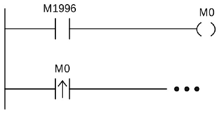
special relays use TD/TD by an indirect method
|
Note: Those marked with “◤” in special relays and temporary registers are forbidden to be written. Meanwhile, this kind of relays are still prohibited/disabling control and forced setting, and TU and TD contacts are not provided. |
2-6 Motion Special Register Details
|
Relay No. |
Function |
System Tag Symbol |
|---|---|---|
|
R36880 |
Motion controller state |
UNIT_STATE |
|
R36881 |
Motion controller error code |
UNIT_ERR |
|
R36882 |
Unit Program State |
UNIT_PROGRAM_STATE |
|
R36883 |
Unit Error Code |
UNIT_ERR_CODE |
|
R36884 – 36903 |
Current Step |
CURRENT_STEP_1 – CURRENT_STEP_20 |
|
R36904 – 36923 |
Current Block State |
CURRENT_BLOCK_STATE_1 – CURRENT_BLOCK_STATE_20 |
|
R36924 – 36943 |
Flow State ID |
FLOW_STATE_ID_1 – FLOW_STATE_ID_20 |
|
DR36964 – 36970 |
Encoder value |
ENCODER_VALUE_2 – ENCODER_VALUE_4 |
|
DR36972 |
Gray code encoder value |
GRAY_CODE_ENCODER_VALUE |
|
DR36974 |
Gray code encoder turns |
GRAY_CODE_ENCODER_TURNS |
※ The table lists the register numbers for axis 1, and for each subsequent axis, the register number is obtained by adding 150*(n-1), ‘n’ represents the axis number.
|
Relay No. |
Function |
System Tag Symbol |
|---|---|---|
|
R36980 + 150*(n-1) |
Axis properties |
TYPE |
|
R36984+ 150*(n-1) |
Current Control Mode |
CTRL_MODE |
|
R37004+ 150*(n-1) |
Error Detail Information 1 |
ERR_INFO_1 |
|
R37005+ 150*(n-1) |
Error Detail Information 2 |
ERR_INFO_2 |
|
R37006+ 150*(n-1) |
Warning Detail Information 1 |
WARN_INFO_1 |
|
R37007+ 150*(n-1) |
Warning Detail Information 2 |
WARN_INFO_2 |
|
R37012+ 150*(n-1) |
Axis Control |
CTRL_STATUS |
|
R37013+ 150*(n-1) |
Axis Warning Code |
WARN_STATUS |
|
DR37014+ 150*(n-1) |
Command Coordinate |
CMD_COOR |
|
DR37016+ 150*(n-1) |
Command Speed |
CMD_VEL |
|
DR37018+ 150*(n-1) |
Command Position |
CMD_PLS |
|
R37020+ 150*(n-1) |
Positioning Current Point No. |
CUR_PT_OR_ECAM_NUM |
|
DR37021+ 150*(n-1) |
Current Coordinate |
CUR_COOR |
|
DR37023+ 150*(n-1) |
Feedback Speed Monitor |
CUR_VEL |
|
DR37025+ 150*(n-1) |
Position Deviation Monitor |
CUR_COOR_DEV |
|
DR37027+ 150*(n-1) |
Digital Input from Driver |
SERVO_DI_VALUE |
|
R37029+ 150*(n-1) |
Current Flow ID |
CUR_FLOW_NUM |
|
DR37030+ 150*(n-1) |
Contact Output |
SYNC_CONT_OUT |
|
R37032+ 150*(n-1) |
Current Torque |
CUR_TORQ |
|
DR37033+ 150*(n-1) |
E-Cam Input Phase |
ECAM_IN_PHASE |
|
DR37035+ 150*(n-1) |
Origin Position |
ORG_PLS |
|
R37037 – R37039+ 150*(n-1) |
Axis Status Word 1-3 |
CONTROL_STATUS_WORD1 |
|
DR37040+ 150*(n-1) |
Main Clutch Output Phase |
MAIN_CLU_INOUT_PHASE |
|
DR37042+ 150*(n-1) |
Probe 1 Coordinate |
PROBE1_COOR |
|
DR37044+ 150*(n-1) |
Probe 2 Coordinate |
PROBE2_COOR |
|
DR37050+ 150*(n-1) |
Axis specifies coordinates |
SET_COOR_VALUE |
|
DR37052+ 150*(n-1) |
Axis advanced control mode |
SET_ADV_MODE |
|
DR37054+ 150*(n-1) |
Axis advanced mode instruction 1 |
SET_ADV_CMD |
|
DR37056+ 150*(n-1) |
Axis advanced mode instruction 2 |
SET_ADV_CMD2 |
|
DR37058+ 150*(n-1) |
Axis advanced mode instruction 3 |
SET_ADV_CMD3 |
|
DR37060+ 150*(n-1) |
Axis advanced mode instruction 4 |
SET_ADV_CMD4 |
|
DR37062+ 150*(n-1) |
Axis advanced mode instruction 5 |
SET_ADV_CMD5 |
|
DR37064+ 150*(n-1) |
Axis advanced mode instruction 6 |
SET_ADV_CMD6 |
|
DR37066+ 150*(n-1) |
Axis advanced mode instruction 7 |
SET_ADV_CMD7 |
Table 1 Motion special register list
Tip: press ← → to switch chapters, Ctrl+K to search