3-1 Sequential Instructions
|
Operand |
Symbol |
Function |
Instruction Type |
|---|---|---|---|
|
X,Y,M, S,T,C |
|
Starting a network with a normally open (A) contact |
Network starting instructions |
|
|
Starting a network with a normally closed (B) contact |
||
|
|
Starting a network with a differential up (TU) contact |
||
|
|
Starting a network with a differential down (TD) contact |
||
|
|
Starting a network with a open circuit contact |
||
|
|
Starting a network with a short circuit contact |
||
|
X,Y,M, S,T,C |
|
Starting a relay circuit from origin or branch line with a normally open contact |
Origin or branch line starting instructions |
|
|
Starting a relay circuit from origin or branch line with a normally closed contact |
||
|
|
Starting a relay circuit from origin or branch line with a differential up contact |
||
|
|
Starting a relay circuit from origin or branch line with a differential down contact |
||
|
|
Starting a relay circuit from origin or branch line with a open circuit contact |
||
|
|
Starting a relay circuit from origin or branch line with a short circuit contact |
||
|
X,Y,M, S,T,C |
|
Serial connection of normally open contact |
Serial connection instructions |
|
|
Serial connection of normally close contact |
||
|
|
Serial connection of differential up contact |
||
|
|
Serial connection of differential down contact |
||
|
|
Serial connection of open circuit contact |
||
|
|
Serial connection of short circuit contact |
||
|
X,Y,M, S,T,C |
|
Parallel connection of normally open contact |
Parallel connection instructions |
|
|
Parallel connection of normally closed contact |
||
|
|
Parallel connection of differential up contact |
||
|
|
Parallel connection of differential down contact |
||
|
|
Parallel connection of open circuit contact |
||
|
|
Parallel connection of short circuit contact |
||
|
|
Serial connection of two circuit blocks |
Blocks merge instructions |
|
|
|
Parallel connection of two circuit blocks |
||
|
Y,M,S |
|
Send result to coil |
Coil output instruction |
|
|
Send inverted result to coil |
||
|
Y |
|
Send result to an external output coil and appoint it as of retentive type |
|
|
TR |
Save the node status to a temporary relay |
Node operation instruction |
|
|
Load the temporary relay |
|||
|
|
Take the transition up of the node status |
||
|
|
Take the transition down of the node status |
||
|
|
Invert the node status |
||
|
|
Set a coil |
||
|
|
Reset a coil |


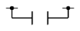
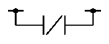
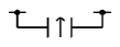
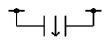
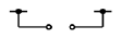
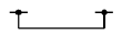


sequential instructions list
※The 36 sequential instructions listed above are all applicable to every models of M – SERIES PLC.
3-2 Function Instructions
There are more than 200 different M PLC function instructions. If put the D and P derivative instructions into account, the total number of instructions is over 300. On top of these, many function instructions have multiple input controls (up to 8 inputs) which can have up to 8 different types of operation mode combinations. Hence, the size of M PLC instruction sets is in fact not smaller than that of a large PLC. Having powerful instruction functions, though may help for establishing the complicated control applications, but also may impose a heavy burden on those users of small type PLC’s. For ease of use, M-Series PLC function instructions are divided into two groups, the Basic function group (The instructions attached with “★” symbol are basic functions which amounts to 26 function instructions and 4 SFC instructions) and the advanced function group.
- Timer/Counter Instructions
|
FUN No |
Name |
Operand |
Derivative Instruction |
Function descriptions |
|---|---|---|---|---|
|
★ |
T nnnn |
PV |
General timer instructions ( “nnnn” range 0~1023, total 1024) |
|
|
★ |
C nnnn |
PV |
General counter instructions ( “nnnn” range 0~1279, total 1280) |
|
|
★ 7 |
UDCTR |
CV,PV |
DP |
16-Bit or 32-Bit up/down counter |
Timer/Counter Instructions list
- Output Operation Instructions
|
★ 4 |
DIFU |
D |
P |
to get the up differentiation of a D relay and store the result to D |
|
★ 5 |
DIFD |
D |
P |
to get the down differentiation of a D relay and store the result to D |
|
★10 |
TOGG |
D |
P |
Toggle the ON/OFF status of the D relay |
Output Operation Instructions List
- Set/Reset Instructions
|
★ |
SET |
D |
DP |
Set all bits of register or a discrete point to 1 |
|
★ |
RST |
D |
DP |
Clear all bits of register or a discrete point to 0 |
Set/Reset Instructions List
- SFC Instructions
|
★ |
STP |
Snnnn |
STEP declaration |
|
|
★ |
STPEND |
End of the STEP program |
||
|
★ |
TO |
Snnnn |
STEP divergent instruction |
|
|
★ |
FROM |
Snnnn |
STEP convergent instruction |
SFC Instructions List
- Arithmetic Instructions
|
★11 |
(+) |
Sa,Sb,D |
D P |
Perform addition of Sa and Sb and then store the result to D |
|
★12 |
(-) |
Sa,Sb,D |
D P |
Perform subtraction of Sa and Sb and then store the result to D |
|
★13 |
(*) |
Sa,Sb,D |
D P |
Perform multiplication of Sa and Sb and then store the result to D |
|
★14 |
(/) |
Sa,Sb,D |
D P |
Perform division of Sa and Sb and then store the result to D |
|
★15 |
(+1) |
D |
D P |
Adds 1 to the D value |
|
★16 |
(−1) |
D |
D P |
Subtracts 1 from the D value |
|
24 |
SUM |
S,N,D |
D P |
Take the sum of the successive N values beginning from S and store it in D |
|
25 |
MEAN |
S,N,D |
D P |
Take the mean average of the successive N values beginning from S and store it in D |
|
27 |
NEG |
D |
D P |
Take the 2’s complement (negative number) of the D value and store it back in D |
|
28 |
ABS |
D |
D P |
Take the absolute value of D and store it back in D |
|
31 |
CRC16 |
MD,S,N,D |
P |
CRC16 caculator |
|
33 |
LCNV |
Md,S,Ts,D,L |
D P |
Linear Conversion |
|
34 |
MLC |
Rs,SI,Tx,Ty,TI,D |
P |
Multiple Linear Conversion |
|
200 |
I→F |
S,D |
D P |
Integer to floating point number conversion |
|
201 |
F→I |
S,D |
D P |
Floating point number to integer conversion |
|
202 |
FADD |
Sa,Sb,D |
P |
Addition of floating point number |
|
203 |
FSUB |
Sa,Sb,D |
P |
Subtraction of floating point number |
|
204 |
FMUL |
Sa,Sb,D |
P |
Multiplication of floating point number |
|
205 |
FDIV |
Sa,Sb,D |
P |
Division of floating point number |
|
206 |
FCMP |
Sa,Sb |
P |
Comparison of floating point number and then store the result to FO0~FO2 |
|
207 |
FZCP |
S,SU,SL |
P |
Comparison of floating point number S to the zones formed by the upper limit SU and the lower limit SL and then store the result to FO0~FO2 |
|
209 |
FSIN |
S,D |
P |
SIN trigonometric function |
|
210 |
FCOS |
S,D |
P |
COS trigonometric function |
|
211 |
FTAN |
S,D |
P |
TAN trigonometric function |
|
212 |
FNEG |
D |
P |
Change sign of floating point number |
|
213 |
FABS |
D |
P |
Take absolute value of floating point number |
|
218 |
FASIN |
S,D,MD |
P |
Floating Point arc sine |
|
219 |
FACOS |
S,D,MD |
P |
Floating Point arc cosine |
|
226 |
MOD |
Sa,Sb,D |
D P |
Modulo (Remainder) |
Arithmetic Instructions List
- Logic Operation Instructions
|
★18 |
AND |
Sa,Sb,D |
D P |
Perform logical AND for Sa and Sb and store the result to D |
|
★19 |
OR |
Sa,Sb,D |
D P |
Perform logical OR for Sa and Sb and store the result to D |
|
35 |
XOR |
Sa,Sb,D |
D P |
Take the result of the Exclusive OR logical operation made between Sa and Sb, and store it in D |
|
36 |
XNR |
Sa,Sb,D |
D P |
Take the result of the Exclusive NOR logical operation made between Sa and Sb, and store it in D |
Logic Operation Instructions List
- Comparison Instructions
|
★17 |
CMP |
Sa,Sb |
D P |
Compare the data at Sa and data at Sb and store the result to FO0~FO2 |
|
37 |
ZNCMP |
S,SU,SL |
D P |
Compare S with the zones formed by the upper limit SU and lower limit SL, and store the result to FO0~FO2 |
|
170 |
= |
Sa,Sb |
D |
Equal to compare |
|
171 |
> |
Sa,Sb |
D |
Greater than compare |
|
172 |
< |
Sa,Sb |
D |
Less than compare |
|
173 |
<> |
Sa,Sb |
D |
Not equal to compare |
|
174 |
>= |
Sa,Sb |
D |
Greater than or equal to compare |
|
175 |
=< |
Sa,Sb |
D |
Less than or equal to compare |
Comparison Instructions List
- Data Movement Instructions
|
★ 8 |
MOV |
S,D |
D P |
Transfer data from S to D |
|
★ 9 |
MOV/ |
S,D |
D P |
Invert data S, and then transfers the result to D |
|
40 |
BITRD |
S,N |
D P |
Read the status of the bits specified by N within S, and send it to FO0 |
|
41 |
BITWR |
D,N |
D P |
Write the INB input status into the bits specified by N within D |
|
42 |
BITMV |
S,Ns,D,Nd |
D P |
Write the status of bit specified by Ns within S into the bit specified by Nd within D |
|
43 |
NBMV |
S,Ns,D,Nd |
D P |
Write the Ns nibble within S to the Nd nibble within D |
|
44 |
BYMV |
S,Ns,D,Nd |
D P |
Write the byte specified by Ns within S to the byte specified by Nd within D |
|
45 |
XCHG |
Da,Db |
D P |
Exchange the values of Da and Db |
|
46 |
SWAP |
D |
P |
Swap the high-byte and low-byte of D |
|
115 |
DBUF |
ID,CH,D |
Store the data form Expansion Module to PLC register |
|
|
160 |
RWFR |
Sa,Sb,Pr,L,Sa |
Read/write file register commands |
|
|
161 |
WR-MP |
S,Bk,Os,Pr,L,WR |
Write memory pack |
|
|
162 |
RD-MP |
Bk,Os,Pr,L,D |
Read memory pack |
Data Movement Instructions List
- Shifting/Rotating Instructions
|
★ 6 |
BSHF |
D |
D P |
shift left or right 1 bit of D register |
|
51 |
SHFL |
D,N |
D P |
Shift left the D register N bits and move the last shifted out bits to FO0. The empty bits will be replaced by INB input bit |
|
52 |
SHFR |
D,N |
D P |
Shift right the D register N bits and move the last shifted out bits to FO0. The empty bits will be replaced by INB input bit |
|
53 |
ROTL |
D,N |
D P |
Rotate left the D operand N bits and move the last rotated out bits to FO0 |
|
54 |
ROTR |
D,N |
D P |
Rotate right the D operand N bits and move the last rotated out bits to FO0 |
Shifting/Rotating Instructions List
- Code Conversion Instruction
|
20 |
→BCD |
S,D |
D P |
Binary to BCD conversion |
|
21 |
→BIN |
S,D |
D P |
BCD to Binary conversion |
|
33 |
LCNV |
Md,S,Ts,D,L |
D P |
Linear conversion |
|
34 |
MLC |
Rs,SI,Tx,Ty,TI,D |
P |
Multiple linear conversion |
|
55 |
B→G |
S,D |
D P |
Binary code to gray code conversion |
|
56 |
G→B |
S,D |
D P |
Gray code to binary code conversion |
|
57 |
DECOD |
S,Ns,N1,D |
P |
Liner decode |
|
58 |
ENCOD |
S,Ns,N1,D |
P |
Encode |
|
61 |
→SEC |
S,D |
P |
Convert the time data (hours, minutes, seconds) of the three successive registers starting from S into seconds data then store to D |
|
62 |
→HMS |
S,D |
P |
Convert the seconds data of S into time data (hours, minutes, seconds) and store the data in the three successive registers starting from D |
|
63 |
→HEX |
S,N,D |
P |
Hexadecimal string to data conversion |
|
64 |
→ASCII |
S,N,D |
P |
Data to hexadecimal string conversion |
Code Conversion Instruction List
- Flow Control Instructions
|
★ 0 |
MC |
N |
The start of master control loop |
|
|
★ 1 |
MCE |
N |
The end of master control loop |
|
|
★ 2 |
SKP |
N |
The start of skip loop |
|
|
★ 3 |
SKPE |
N |
The end of skip loop |
|
|
END |
End of Program |
|||
|
22 |
BREAK |
P |
Exit from FOR-NEXT loop |
|
|
65 |
LBL |
1~6 alphanumeric |
Define the label with 1~6 alphanumeric characters |
|
|
66 |
JMP |
LBL |
P |
Jump to LBL label and continues the program execution |
|
67 |
CALL |
LBL |
P |
Call the sub-program begin with LBL label |
|
68 |
RTS |
Return to the calling main program from sub-program |
||
|
69 |
RTI |
Return to interrupted main program from sub-program |
||
|
70 |
FOR |
N |
Define the starting point of the FOR Loop and the loop count N |
|
|
71 |
NEXT |
Define the end of FOR loop |
||
|
165 |
FLBL |
LBL |
Define the label with 1~6 alphanumeric characters in FCM. |
|
|
166 |
FJMP |
LBL |
P |
Jump to LBL label and continues the program execution in FCM |
|
199 |
TXTDF |
LN |
Ladder Program blocking function |
Flow Control Instructions List
- PID Control
|
30 |
PID |
Ts,SR,OR,PR,WR |
D |
General PID operation (Main Unit) |
|
38 |
PID2 |
ID,CH,SR,OR,PR,WR |
General PID operation (Expansion Module) |
|
|
99 |
TPCTL2 |
ID,CH,SR,PR,OR,WR |
PID for temperature control (Expansion Module) |
PID Control List
- I/O Instructions
|
74 |
IMDIO |
D,N |
P |
Update the I/O signal on the main unit immediately |
|
83 |
SPD |
S,TI,D |
Speed detection |
I/O Instructions List
- Cumulative Timer Instructions
|
87 |
T.01S |
CV,PV |
Cumulative timer using 1mS as the time base |
|
|
88 |
T.1S |
CV,PV |
Cumulative timer using 10mS as the time base |
|
|
89 |
T1S |
CV,PV |
Cumulative timer using 100mS as the time base |
Cumulative Timer Instructions List
- Watch Dog Timer Instructions
|
90 |
WDT |
N |
P |
Set the WDT timer time out time to N mS |
|
91 |
RSWDT |
P |
Reset the WDT timer to 0 |
Watch Dog Timer Instructions List
- High Speed Counter / Timer Instructions
|
92 |
HSCTR |
CN |
DP |
Read the current CV value of the hardware HSCs, HSC0~HSC3, or HST on SOC to the corresponding CV register in the PLC respectively |
|
93 |
HSCTW |
S,CN,D |
DP |
Write the CV or PV register of HSC0~HSC3 or HST in the PLC to CV or PV register of the hardware HSC or HST on SOC respectively |
High Speed Counter / Timer Instructions List
- Ramp / Soak Instructions
|
98 |
RAMP2 |
Om,Ta Td,Rt Rc,WR |
Tracking type ramp function for analog output |
Ramp / Soak Instructions List
- Communication Function Instructions
|
150 |
M-Bus |
Pt,SR,WR |
P |
Modbus protocol communication instruction |
|
151 |
CLINK |
Pt,MD,SR,WR |
P |
FATEK/Generic protocol communication instruction |
|
152 |
NCR |
Active network communication |
||
|
156 |
CMCTL |
ID,Pt,Ts,MD,WR |
Communication module instruction |
Communication Function Instructions List
- Table Manipulation Instructions
|
100 |
R→T |
Rs,Td,L,Pr |
D P |
Register to table data move |
||
|
101 |
T→R |
Ts,L,Pr,Rd |
D P |
Table to register data move |
||
|
102 |
T→T |
Ts,Td,L,Pr |
D P |
Table to table data move |
||
|
103 |
BT_M |
Ts,Td,L |
D P |
Copy the entire contents of Ts to Td |
||
|
105 |
R-T_S |
Rs,Ts,L,Pr |
D P |
Table data seek |
||
|
106 |
T-T_C |
Ta,Tb,L,Pr |
D P |
Table compare |
||
|
107 |
T_FIL |
Rs,Td,L |
D P |
Fill the table Td with Rs |
||
|
108 |
T_SHF |
IW,Ts,Td,L,OW |
D P |
Table shift |
||
|
109 |
T_ROT |
Ts,Fd,L |
D P |
Table rotate |
||
|
110 |
QUEUE |
IW,Qu,L,Pr,OW |
D P |
Data queue(FIFO) |
||
|
111 |
STACK |
IW,ST,L,Pr,OW |
D P |
Data stack(FILO) |
||
|
112 |
BKCMP |
Rs,Ts,L,D |
D P |
Block compare(CAM switch) |
||
|
113 |
SORT |
S,D,L |
D P |
Sorting the registers starting from S length L and store the sorted result to D |
||
|
114 |
Z-WR |
N |
P |
Zone set or clear |
||
Table Manipulation Instructions List
- Matrix Manipulation Instructions
|
120 |
MAND |
Ma,Mb,Md,L |
P |
Matrix AND |
|
121 |
MOR |
Ma,Mb,Md,L |
P |
Matrix OR |
|
122 |
MXOR |
Ma,Mb,Md,L |
P |
Matrix exclusive OR |
|
123 |
MXNR |
Ma,Mb,Md,L |
P |
Matrix enclusive OR |
|
124 |
MINV |
Ms,Md,L |
P |
Matrix invert |
|
126 |
MBRD |
Ms,L,Pr |
P |
Matrix bit read |
|
128 |
MBSHF |
Ms,Md,L |
P |
Matrix bit shift |
|
129 |
MBROT |
Ms,Md,L |
P |
Matrix bit rotate |
|
130 |
MBCNT |
Ms,L,D |
P |
Calculate the total number of bits that are 0 or 1 in Ms, then store the results into D |
Matrix Manipulation Instructions List
- NC Positioning Instruction
|
137 |
ICA |
Ps,Is,Po,Ag |
Interrupt Constant Angle |
|
|
138 |
ICF |
Ps,Is,Po,Pd |
Interrupt Constant Feed |
|
|
139 |
HSPWM |
Pw,Op,Rs,Pn,OR,WR |
High Speed PWM |
|
|
140 |
HSPSO |
Ps,SR,WR |
HSPSO instruction of NC positioning control |
|
|
141 |
MPARA |
Ps,SR |
Parameter setting instruction of NC positioning control |
|
|
142 |
PSOFF |
Ps |
P |
NC pulse output |
|
143 |
PSCNV |
Ps,D |
P |
Position of pulse unit to engineering unit convert |
|
144 |
HSPWM2 |
Pw,Op,Hz,OR |
High Speed PWM (Mode2) |
|
|
147 |
MHSPO |
Gp,SR,WR |
Multi-Axis high speed pulse output |
|
|
148 |
MPG |
Sc,Ps,Po,Mr,WR |
Manual Pulse |
NC Positioning Instruction List
- Interrupt Control Instruction
|
145 |
EN |
LBL |
P |
Enable HSC, HST, external INT or peripheral operation |
|
146 |
DIS |
LBL |
P |
Disable HSC, HST, external INT or peripheral operation |
Interrupt Control Instruction List
- Floating Point Number Instruction
|
200 |
I→F |
S,D |
D P |
Conversion of integer to floating point munber |
|
201 |
F→I |
S,D |
D P |
Conversion of floating point munberto integer |
|
202 |
FADD |
Sa,Sb,D |
P |
Floating point number addition |
|
203 |
FSUB |
Sa,Sb,D |
P |
Floating point number subtraction |
|
204 |
FMUL |
Sa,Sb,D |
P |
Floating point number multiplication |
|
205 |
FDIV |
Sa,Sb,D |
P |
Floating point number divsion |
|
206 |
FCMP |
Sa,Sb |
P |
Floating point number compare |
|
207 |
FZCP |
S,Su,Sl |
P |
Floating point number zone compare |
|
208 |
FSQR |
S,D |
P |
Floating point number square root |
|
209 |
FSIN |
S,D |
P |
Sin trigonometric instruction |
|
210 |
FCOS |
S,D |
P |
Cos trigonometric instruction |
|
211 |
FTAN |
S,D |
P |
Tan trigonometric instruction |
|
212 |
FNEG |
D |
P |
Change sign of the floating point number |
|
213 |
FABS |
D |
P |
Floating point number absolute value |
|
218 |
FASIN |
S,D,MD |
P |
Floating Point arc sine |
|
219 |
FACOS |
S,D,MD |
P |
Floating Point arc cosine |
Floating Point Number Instruction
- Module Function Instruction
|
258 |
MODCONF |
OP,ID,CH,SB |
Module configuration setting |
Module Function Instruction List
- Motion Basic Instruction
|
177 |
MFSysStop |
Control motion system stop |
||
|
185 |
MFSysRstAlm |
Reset motion alarm status |
||
|
187 |
MFSysInit |
Servo initialization |
||
|
188 |
MFSysRCPR |
Md,D,Gp |
Read motion recipe |
|
|
189 |
MFSysRCPW |
Md,D,Gp |
Write motion recipe |
|
|
191 |
MFSysCAMR |
Md,D,ID,L |
Motion CAM read |
|
|
192 |
MFSysCAMW |
Md,D,ID,L |
Motion CAM write |
|
|
196 |
MFSysCAMGen |
ID,Md,D,L |
Motion CAM Generation |
|
|
235 |
MFSysSetVirt |
AX |
Set real axis to virtual axis |
|
|
236 |
MFSDOR |
S,I,SI,LN,EC,D |
Read EtherCAT slave parameters |
|
|
237 |
MFSDOW |
S,I,SI,LN,EC,D |
Write EtherCAT slave parameters |
Motion Basic Instruction list
- Motion Mode 1 Instruction
|
176 |
MFFlowStart |
ID |
Start the motion flow |
|
|
181 |
MFChgTbPrm |
Gp,ID,N,D |
Change motion parameters |
|
|
182 |
MFFlowPause |
ID |
Pause the motion flow |
|
|
183 |
MFFlowResume |
ID |
Resume the motion flow |
|
|
184 |
MFFlowHalt |
ID |
Halt the motion flow |
|
|
186 |
MFFlowStop |
ID |
Stop the motion flow |
|
|
198 |
MFMapTbPrm |
Gp,N,L |
Set Motion Parameter Mapping Data |
Motion Mode 1 list
- Motion Mode 2 Instruction
|
178 |
MFHome |
AX |
Control the axis homing |
|
|
179 |
MFPointMov |
PT |
Start point position control |
|
|
180 |
MFJog |
AX,D,MD |
Control the axis homing |
|
|
181 |
MFChgTbPrm |
Gp,ID,N,D |
Change motion parameters |
|
|
198 |
MFMapTbPrm |
Gp,N,L |
Set Motion Parameter Mapping Data |
Motion Mode 2 Instruction list
- Motion Mode 3 Instruction
|
178 |
MFHome |
AX |
Control the axis homing |
|
|
180 |
MFJog |
AX,D,MD |
Control the axis homing |
|
|
193 |
MFGearMPG |
M,S,N,D,T |
D |
Motion axis gear in |
|
194 |
MFVelCtl |
AX,V,MX |
D |
Motion Velocity Control |
|
195 |
MFTorqCtl |
AX,T,MXf |
D |
Motion Torque Control |
|
197 |
MFAxMov |
AX,MD,Ps,V,A,D,SA,SD,DR,BP |
D |
Motion Axis Movement |
|
238 |
MFAxLMov |
TAX,MD,DR,BF,D,EC |
Move axes along a linear path |
|
|
239 |
MFAxCirMov |
TAX,MD,DR,BF,D,EC |
Move axes along a circular path |
|
|
240 |
MFPathMov |
AX1,AX2,AX3,PT,V,TA,TD,SA,SD,EC |
Motion Mode 3 Instruction list
Tip: press ← → to switch chapters, Ctrl+K to search