Axis Parameters and Setting
This section describes the parameter setting and the axis connection setting related information that will be required for connecting M-PLC to EtherCAT Servo. The user will be allowed to set the axis connection and axis parameter setting through FATEK program editing software UperLogic.
4-1 Motion Network Setting
To run the UperLogic editing software, it is required to click open the motion connecting setting page on the left-hand side window. To add the EtherCAT Servo for both axes, input the EtherCAT Servo ESI File by pressing the import ESI button. After importing the ESI File, drag the right-hand side toolkit column to the field underneath the left-hand side Motion Control and then the system will log the Axis model number and brand automatically.
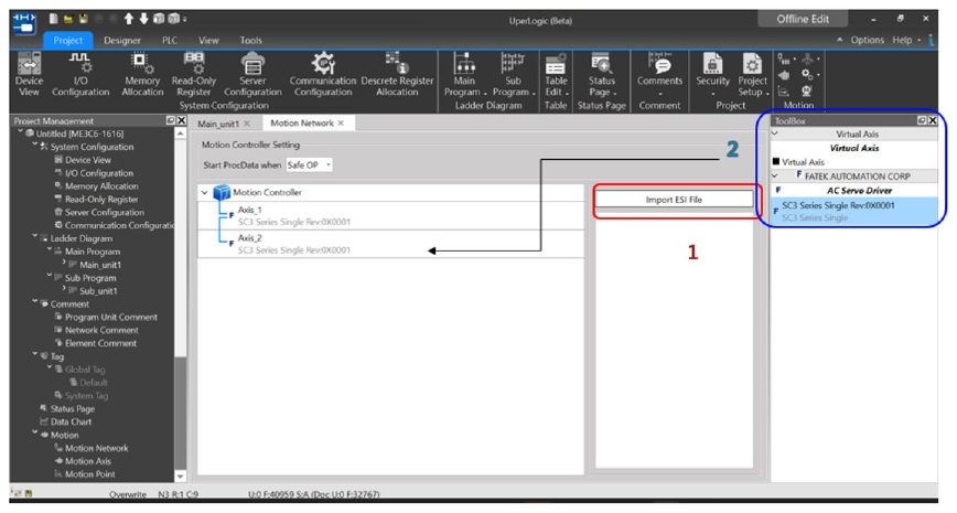
If the axis connection setting is different from the equipment actually connected, such as unit number, type and sequence, then the system will indicate an error and will not execute the communication.
- Notes for connecting FATEK SC3
Use Speed mode Pn002 □□□1h must be set
Use Torque mode Pn002 □□1□h must be set
Use Absolute Value encoder Pn002 □0□□h must be set
4-2 Motion Axis Parameter Setting
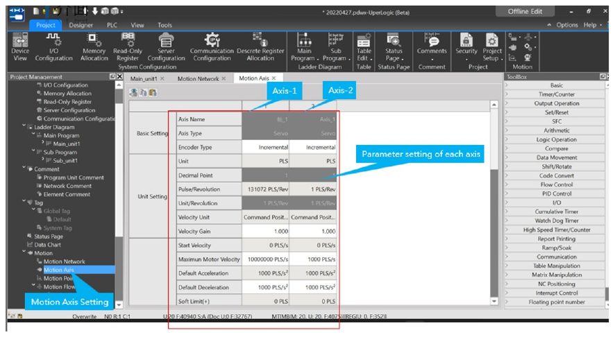
After completing the motion axis connection, the user may set up the parameters for each axis through UperLogic. Described below is the detailed parameter setting.
Indicated below is the UperLogic axis parameter setup page.
Basic Setting:
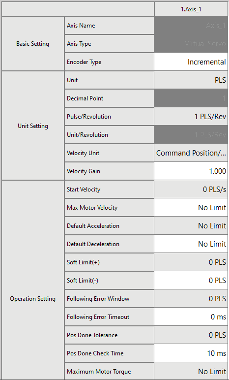
Axis name: To change the axis name, set up the “Device Name” on motion link. By changing the axis name, the user will be allowed to differentiate the application of each axis.
Encoder type: Incremental (the location information will disappear once the power is turned off), Absolute (the location information is kept, so it can continue to operate without HOME return after the power is restored)
Axis Type:
Servo: Physical axis
Virtual Servo: Virtual axis
Unit Setting:
Unit: Comprising 4 kinds of units and they are PLS, mm, deg and inch.
Decimal point: It allows the user to set up smaller units during the setup process (mm/deg/inch) for up to 3 places after the decimal point.
Pulse/Revolution: The pulse number of the motor during each revolution of operation.
Unit/Revolution: The distance achieved by the motor during each revolution of operation.
Velocity Unit: The watch table displays the velocity unit returned by the selected driver.
Velocity Gain: Select the minimum scale of the velocity returned by the driver.
Operation Setting:
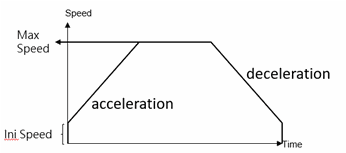
Initial Speed: The initial speed required for running the motor.
Max. Motor Speed: The maximum speed for limiting the motor at PLC end. If the command exceeds such speed, the PLC will signal the alarm and the servo will remain inactive accordingly.
Maximum Acceleration: The maximum acceleration required for limiting the motor at PLC end.
Maximum Deceleration: The maximum deceleration required for limiting the motor at PLC end.
Soft Limit (+): The limit required for restricting forward running at PLC end.
Soft Limit (-): The limit required for restricting backward running at PLC end.
If the same value is set for soft limit (+) and soft limit (-), then the soft limit shall be regarded as limitless. For example, if both of them are set as “0”, then the soft limit will not provide the protection.
Tracking error allowable scope: Allowable error range between motor feedback position and PLC command position.
Tracking error allowable time: Allowable error timeout between motor actual position and command position.
Positioning complete allowable error: The error scope within which the motor has reached the command position.
Positioning complete checking time: The error timeout within which the motor has reached the command position.
Max. Motor Torque: The maximum torque required for limiting the motor at the driver end. It must be lower than the motor specifications and shall be carried to the first place after the decimal point.
Note: Speed mode and torque mode will be excluded.
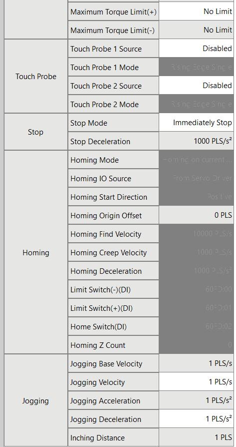
Max. Torque Limit (+): The torque limit required for restricting forward running at the PLC end, and it shall be carried to the first place after the decimal point.
Max. Torque Limit (-): The torque limit required for restricting backward running at the PLC end, and it shall be carried to the first place after the decimal point.
Probe:
When to use: The Probe Function is also called the Position Latch Function. The value of the servo axis or encoder is latched in real time through the external DI signal and Z signal. The probe function is suitable for applications where position synchronization is required, such as die-cutting and printing.
Probe 1 source: Set the probe number and source of the drive to be used.
Probe 1 mode: Set the mode to trigger the drive probe function.
Probe 2 source: Set the probe number and source of the drive to be used.
Probe 2 mode: Set the mode to trigger the drive probe function.
Stop:
Stop Mode: Set up the motor stop mode when the action alarm is running.
Stop deceleration: Set up the deceleration during the deceleration stopping.
HOME Return:
Return mode: Select the HOME Return mode for the axis. For details, please refer to Chapter 10: HOME Return Mode.
Return IO Source: It can upload the signal from the driver to the PLC through EtherCAT or the PLC special register.
Return Start Direction: The start direction required for setting up the HOME searching.
HOME Return Offset: The offset value is the coordinates of the location where the origin mode is done.
Return searching speed: Set up the speed required for searching the HOME (can be faster than the set value).
Return crawl speed: Set up the crawling speed required for entering the scope of HOME (to be set at slower speed).
Return deceleration: Set up the deceleration required for entering the scope of HOME.
Limit Switch (-) (DI): Set up the bit when Limit Switch reaches 60FDh, and it is normally preset as “0”. For detailed bit, please refer to Driver Manual.
Limit Switch (-) (DI): Set up the bit when Limit Switch reaches 60FDh, and it is normally preset as “1”. For detailed bit, please refer to Driver Manual.
HOME Sensor (DI): Set up the bit when HOME Sensor reaches 60FDh, and it is normally preset as “2”. For detailed bit, please refer to Driver Manual.
HOME Z-phase signal number: When finding out the Z-HOME Mode, the Z signal that has blocked the DOG Sensor will be regarded as the HOME. If setting at “0”, then it will be regarded as the HOME when blocking the DOG Sensor.
JOG:
JOG Start Speed: The starting speed when operating under JOG Mode.
JOG Speed: The max. speed when operating under JOG Mode.
JOG Acceleration: The acceleration when operating under JOG Mode.
JOG Deceleration: The deceleration when operating under JOG Mode.
JOG Distance: The JOG distance when operating under JOG Mode.
Tip: press ← → to switch chapters, Ctrl+K to search