Position Control and Interpolation
This section describes the positioning control and the interpolation functions. When using the positioning and the motion control functions, you may use the action type of each axis as the reference for setting the desired point parameters such as action mode, target coordinates, acceleration/deceleration or other settings like the number of next point as well as the continuing mode and the transfer conditions, etc. The point parameters can be set according to the number of the point desired. By changing the designated point code, the user will be allowed to run the desired positioning motion with the positioning program that is listed in the point table of the Motion Flow Block.
8-1 Using M-PLC Position Control Flow
Listed below are the steps required for using the Motion Flow related positioning control or interpolation functions:
|
No. |
Action |
Remark |
|
1 |
Complete the setting of motion link |
Refer to Section 3.1 |
|
2 |
Compete the setting of motion axis parameters |
Refer to Section 3.2 |
|
3 |
Create Ladder and Motion Flow |
Refer to Section 6 |
|
4 |
Set the positioning point parameter |
Refer to Section 4 |
|
Action Flow after PLC execution: |
||
|
5 |
Execute Initial EtherCAT communication through Ladder programming |
Refer to Section 5.1 |
|
6 |
Execute Servo ON through Ladder programming |
Refer to Section 1.2 Ex. Axis 1 turn on M10600 |
|
7 |
Execute return to HOME if accessing the mechanism. |
Refer to Section 6.7 and Section 10 |
|
8 |
Execute the positioning control |
Refer to Section 6.6 |
8-2 Using Ladder Position Control
8-2-1 HOME Return (MFHome)
|
FUN 178 MFHome |
HOME Return (MFHome) |
FUN 178 MFHome |
||||||||||||||||||||||||||||||||||||||||||||||
|
Command Description |
||||||||||||||||||||||||||||||||||||||||||||||||
|
|
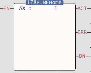
AX : Axis No. to execute HOME Return EN : = 1, indicates that a HOME Return is to be performed ACT : = 1, indicates that the HOME Return operation is in progress ERR : = 1, indicates HOME Return error DN : = 1, indicates HOME Return is done |
|||||||||||||||||||||||||||||||||||||||||||||||
|
||||||||||||||||||||||||||||||||||||||||||||||||
|
Function Description |
||||||||||||||||||||||||||||||||||||||||||||||||
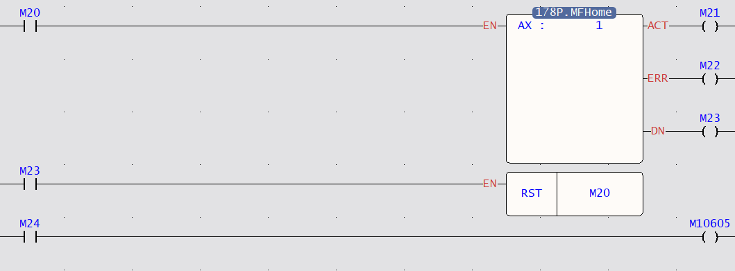
In the special register, there are also corresponding contacts to indicate the state of homing, as follows: M11245: Axis 1 is returning to HOME M11246: Axis 1 HOME return operation completed M10605: Axis 1 HOME signal
|
||||||||||||||||||||||||||||||||||||||||||||||||
|
FUN178P MFHome |
HOME Return (MFHome) |
FUN178P MFHome |
||||||||||||||||||||||||||||||||||||||||||||||
|
Program Example |
||||||||||||||||||||||||||||||||||||||||||||||||
|
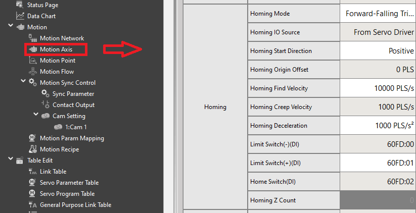
If users want to make the homing of the axis in Dog Forward mode, and the homing IO source signal is controlled by PLC, it will decelerate to a homing crawling speed of 250 mm/s2 when encountering the Dog signal, and stop until it leaves the Dog signal , set in axis 1 of “Motion Axis Setting”, as shown in the figure below.
Edit the program in Ladder as shown below: |
||||||||||||||||||||||||||||||||||||||||||||||||
|
FUN178P MFHome |
HOME Return (MFHome) |
FUN178P MFHome |
|
Program Example |
||
|
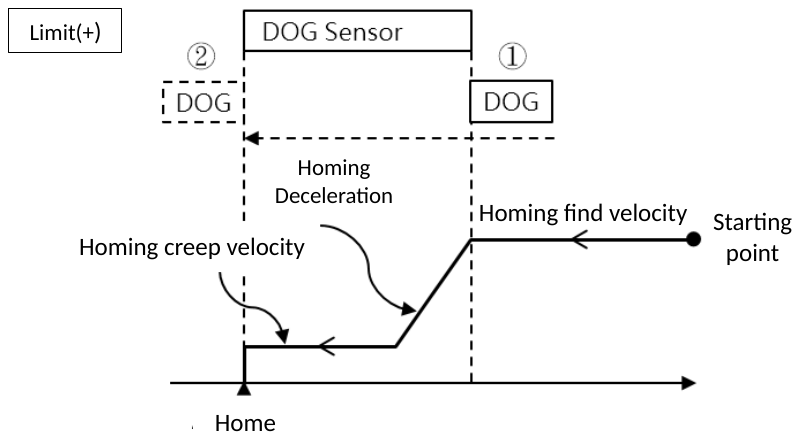
The program and action description are shown in the figure below:
When M 20 is turned ON by the upper edge trigger, it will move forward at the return search speed of 500 mm/s.
|
||
8-2-2 Position Control (MFPointMov)
|
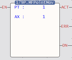
Fun179P MFPointMov |
Position Control (MFPointMov) |
Fun179P MFPointMov |
|||||||||||||||||||||||||||||||||||||||||||||||||||||||||||||
|
Command Description |
|||||||||||||||||||||||||||||||||||||||||||||||||||||||||||||||
|
|
PT:Command No. of Motion Point Table AX :Motion control axis No. ACT:Acting ERR:Error DN:Done |
||||||||||||||||||||||||||||||||||||||||||||||||||||||||||||||
|
|||||||||||||||||||||||||||||||||||||||||||||||||||||||||||||||
|
Function Description |
|||||||||||||||||||||||||||||||||||||||||||||||||||||||||||||||
|
|||||||||||||||||||||||||||||||||||||||||||||||||||||||||||||||
|
Fun179P MFPointMov |
Position Control (MFPointMov) |
Fun179P MFPointMov |
|
Program Eample |
||
|
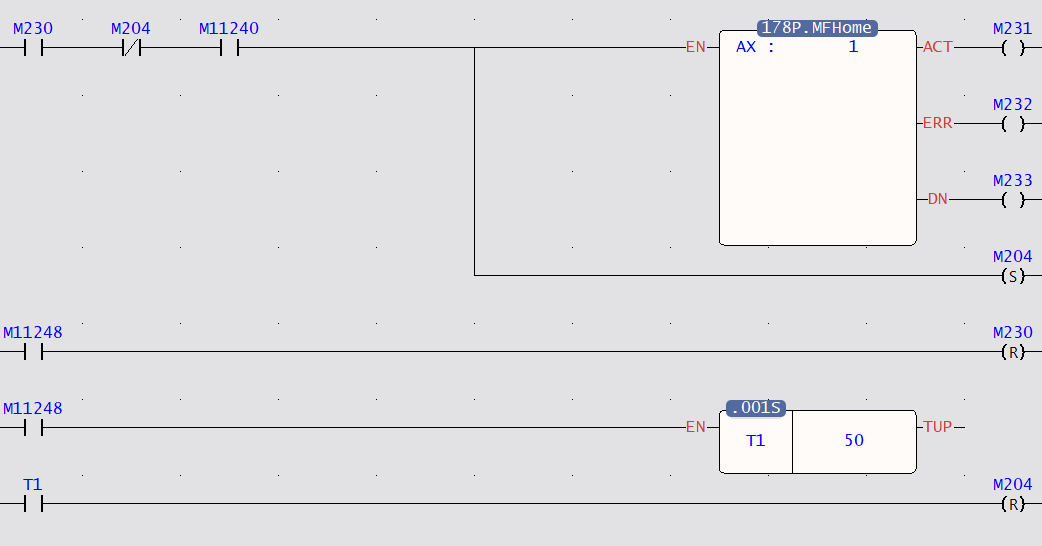
1. Trigger M230 to perform position control 2. When the position control action is completed, use M11248 to clear M230 *Use M204 to prevent other Fun179 triggers from causing errors |
||
8-2-3 JOG (MFJog)
|
Fun 180 MFJog |
JOG (MFJog) |
Fun 180 MFJog |
|||||||||||||||||||||||||||||||||||||||||||||||||||||||||||||
|
Command Description |
|||||||||||||||||||||||||||||||||||||||||||||||||||||||||||||||
|
|
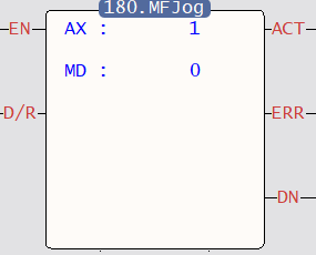
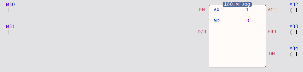
AX :Indicates the axis to perform JOG MD : There are 4 modes in total, mode 0-mode 3, for detailed information, please refer to the instructions in the motion control manual. EN : = 1, indicates Indicates that JOG is to be triggered. D/R : = 1, Forward ; D/R : = 0, Backward ACT : = 1, JOG is acting ERR : = 1, JOG error DN : = 1, JOG is done |
||||||||||||||||||||||||||||||||||||||||||||||||||||||||||||||
|
|||||||||||||||||||||||||||||||||||||||||||||||||||||||||||||||
|
Function Description |
|||||||||||||||||||||||||||||||||||||||||||||||||||||||||||||||
M10625: Axis 1 is in JOG operation. M11240: The JOG operation of axis 1 is completed.
|
|||||||||||||||||||||||||||||||||||||||||||||||||||||||||||||||
|
Fun180 MFJog |
JOG (MFJog) |
Fun180 MFJog |
|
Program Example |
||
|
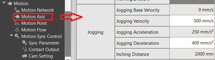
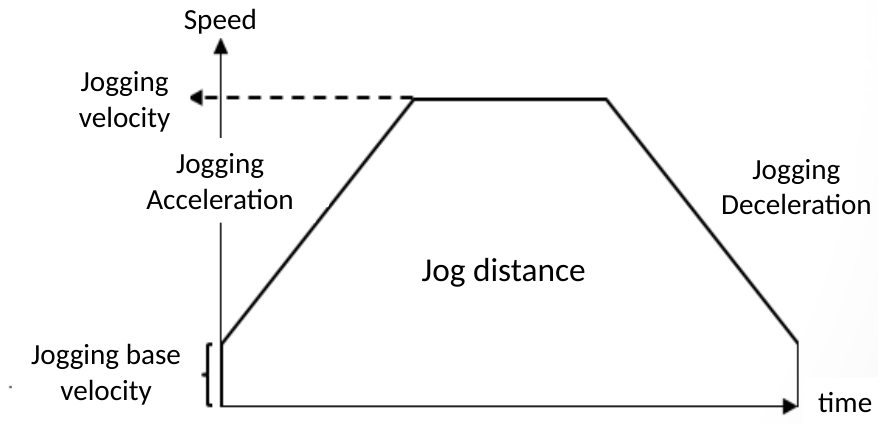
If users want to move the axis by 2000 mm, accelerate to 500 mm/s with JOG acceleration 250 mm/s2, and decelerate with JOG deceleration 400 mm/s2, set axis 1 in “Motion Axis Setting”, As shown below:
Edit the program in Ladder as shown below:
|
||
|
Fun180 MFJog |
JOG (MFJog) |
Fun180 MFJog |
|
Program Example |
||
|
The program and action description are shown in the figure below:
|
||
8-2-4 Axis Movement (MFAxMov)
|
FUN197 MFAxMov |
Axis Movement |
FUN197 MFAxMov |
|||||||||||||||||||||||||||||||||||||||||||||||||||||||||||||||||||||||||||||||||||||||||||||||||||||||||||||||||||||||||||||||||||||||||||||||||||||||||||||||||||||||||||||||||||||
|
Command Description |
|||||||||||||||||||||||||||||||||||||||||||||||||||||||||||||||||||||||||||||||||||||||||||||||||||||||||||||||||||||||||||||||||||||||||||||||||||||||||||||||||||||||||||||||||||||||
|
|
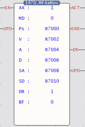
AX: Axis No. Md : Mode 0:Abbsolute 1:Relative Ps:Coordinates, unit: 0.01 V: Velocity A: Acceleration D: Deceleration SA : Accelerated S Curve SD : Decelerated S Curve DR : Direction; 1: Forward, 2 : Backward BF : Consecutive Velocity Mode 0 = Execute the current command immediately 1 = Wait for the previous command to finish 2 = Select lower consecutive velocity 3 = Select the previous velocity command 4 = Select the current velocity command 5 = Select higher consecutive velocity EN:Trigger command UPD:Updated rising parameter ACT:Master axis and Slave axis are synchronozing ERR:Parameter error or axis error DN: Motion OS : v_0.5.9 currently has no features UPDN:Updating parameter is done |
||||||||||||||||||||||||||||||||||||||||||||||||||||||||||||||||||||||||||||||||||||||||||||||||||||||||||||||||||||||||||||||||||||||||||||||||||||||||||||||||||||||||||||||||||||||
|
FUN 197 ME_AXI_MV |
Axis Movement |
FUN 197 ME_AXI_MV |
|||||||||||||||||||||||||||||||||||||||||||||||||||||||||||||||||||||||||||||||||||||||||||||||||||||||||||||||||||||||||||||||||||||||||||||||||||||||||||||||||||||||||||||||||||||
|
|||||||||||||||||||||||||||||||||||||||||||||||||||||||||||||||||||||||||||||||||||||||||||||||||||||||||||||||||||||||||||||||||||||||||||||||||||||||||||||||||||||||||||||||||||||||
|
Function Decription |
|||||||||||||||||||||||||||||||||||||||||||||||||||||||||||||||||||||||||||||||||||||||||||||||||||||||||||||||||||||||||||||||||||||||||||||||||||||||||||||||||||||||||||||||||||||||
|
|||||||||||||||||||||||||||||||||||||||||||||||||||||||||||||||||||||||||||||||||||||||||||||||||||||||||||||||||||||||||||||||||||||||||||||||||||||||||||||||||||||||||||||||||||||||
|
Program Example |
|||||||||||||||||||||||||||||||||||||||||||||||||||||||||||||||||||||||||||||||||||||||||||||||||||||||||||||||||||||||||||||||||||||||||||||||||||||||||||||||||||||||||||||||||||||||
|
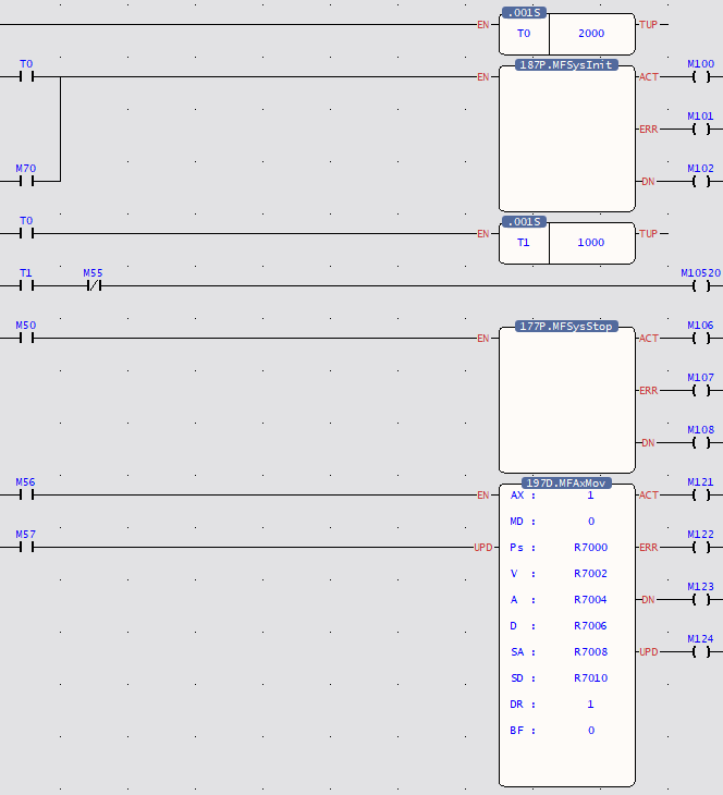
Program example is shown below:
|
|||||||||||||||||||||||||||||||||||||||||||||||||||||||||||||||||||||||||||||||||||||||||||||||||||||||||||||||||||||||||||||||||||||||||||||||||||||||||||||||||||||||||||||||||||||||
|
FUN 197 ME_AXI_MV |
Axis Movement |
FUN 197 ME_AXI_MV |
|||||||||||||||||||||||||||||||||||||||||||||||||||||||||||||||||||||||||||||||||||||||||||||||||||||||||||||||||||||||||||||||||||||||||||||||||||||||||||||||||||||||||||||||||||||
|
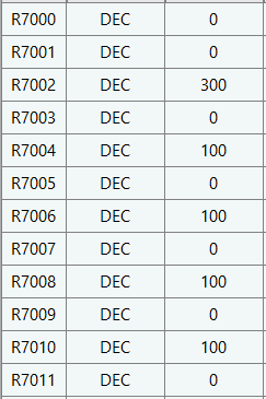
In accordance with the register location of the command plan, fill in the parameters in the following table:
This program example will initialize the motion control system 3 seconds after the first execution, and will enable all axes (Servo on) after 3 seconds, and then fill in the parameters in order, and then turn M56 on to execute the position according to The set acceleration and deceleration etc. move to the place where the absolute position is 300 PLS. |
|||||||||||||||||||||||||||||||||||||||||||||||||||||||||||||||||||||||||||||||||||||||||||||||||||||||||||||||||||||||||||||||||||||||||||||||||||||||||||||||||||||||||||||||||||||||
8-3 Using Motion Flow Positioning
The M-PLC positioning can be controlled with the following two methods, Ladder and Motion Flow. To control with Motion Flow method, you need to select positioning control Block from the PLC program. When using Motion Flow to execute the positioning control, you need to select the parameter from the point table.
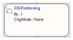
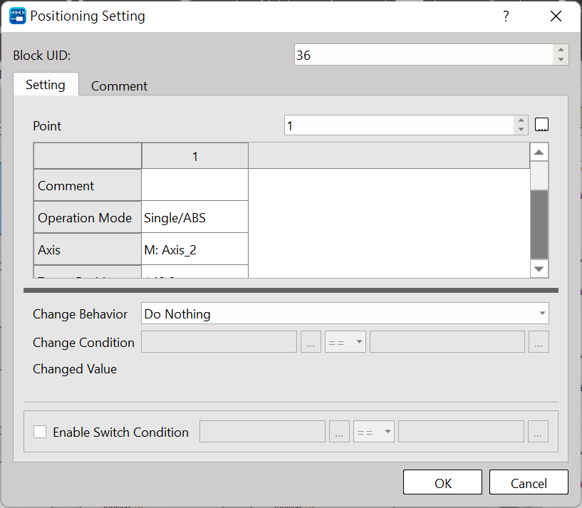
Flow Block ID: The ID will be assigned by the system automatically, but it can be changed by the user as desired.
Point: Point Parameter Table. I. If the motion parameter data in Point 9 equals to Point Parameter 9, then the user may set up the point motion parameter in motion parameter. When running the flow, you may write the motion data for the desired point and the system will log such data in the Point Parameter Table automatically.
Change Behavior: No change / Change current coordinate / Change target position / Change speed / Interrupt Constant Feed / Interrupt Constant Angle
Provided below are the rules that should be followed when executing the speed change, target coordinates change and current coordinates change:
1. Speed change rules:
a. If the residual moving distance is too short after changing the speed, then the system will not change the speed. In this case, the system will run the flow according to the speed previously used.
b. Change the Master Axis speed. In case of arc or linear interpolation, change the composition speed created for the interpolation.
c. After changing the speed for the current point, the composite speed or the Master Axis speed will not be changed when using the point parameter of the next point. The system will change the speed when setting the speed of the subsequent point parameter at “-1”.
Note: The Error will present when setting the starting point speed at “-1”.
d. When setting the speed change value at “0”, the flow will slow down and then stop.
2. Target coordinates change rules:
a. When executing continuous parameter action, you cannot change current coordinates.
b. If current action is arc spiral interpolation type, then the change will be ineffective.
3. Change current coordinates
a. When executing the positioning control, you cannot change the coordinates.
b. You may select Standby after current point parameters are running. After selecting Standby, you may change the coordinates and then use the changed coordinate system for the next point.
Change Condition: The condition required for changing the behavior. If the change behavior has been set, then you need to set up the required change condition.
Switch Condition: The condition required for switching to the next flow block. If the switch condition remains inactive, then you may jump to the next flow block directly.
In addition, you can use FUN181 to change the motion control parameter command, and make various numerical changes according to the above rules. For detailed operation methods, please refer to Chapter 6-12.
Introduction of motion point parameter setting:
Point ID: The ID number of the point that will be executed on Ladder.
Motion mode: Such option is used for selecting absolute/relative/interpolation motions.
Master Axis: The ID number of the axis that will be executed.
Target Position: Master Axis target position, which means the travel (relative/absolute) that will be moved.
Speed: Output speed or the maximum speed of frequency motion. Such value will not be added if the distance is not enough for accelerating to the maximum.
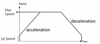
Acceleration: The acceleration required for increasing the initial speed to the desired speed.
Deceleration: The deceleration required for reducing the initial speed to the desired speed.
Acceleration type: T-curve/ S-curve
S-acceleration curve percentage scope: 1%–100%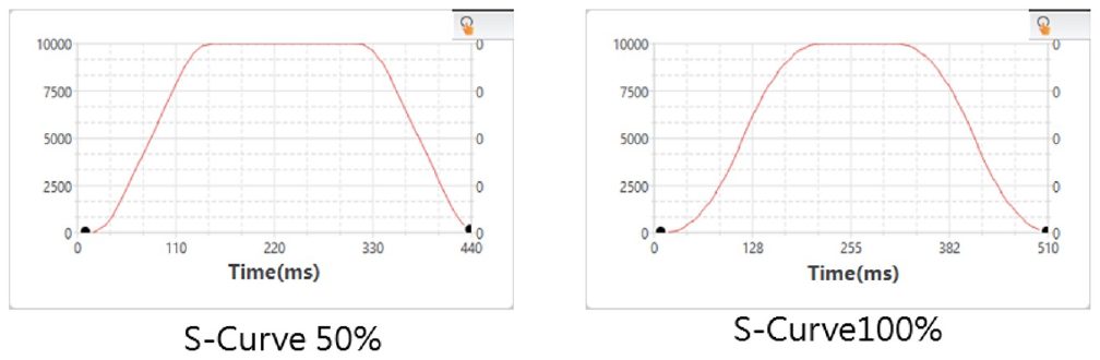
S-deceleration curve percentage scope: 1%–100%
Where, 0% means pure T-curve and 100% refers to pure S-curve (without uniform acceleration/deceleration field)
Consecutive Point: The point required for ending or continuing the motion. If continue motion will be required, then select Continue Mode.
Consecutive Mode:
Standby: The “ms” duration that should be elapsed after completing the current point so as to move to the next point.
Next point consecutive speed: The speed for accelerating/decelerating to the next point and then run the next point.
Current point consecutive speed: Complete with current speed and then execute acceleration/deceleration until reaching the next point.
Start consecutive speed: Reduce the speed to starting speed and then run the next point.
Standby time: The standby duration under Standby Mode (unit: ms)
8-4 Description of Multi-axis Interpolation
M-PLC positioning control is composed by Linear Interpolation, Arc Interpolation and Spiral Interpolation modes.
The Linear Interpolation provides maximum 4-axis linear interpolation control.
The Arc Interpolation provides maximum 2-axis arc interpolation control.
The Spiral Interpolation provides maximum 3-axis spiral interpolation control.
Listed below is the classification of action mode:
|
Interpolation Mode |
Linear Interpolation |
Arc Interpolation |
Spiral Interpolation |
|
Control System |
Position control |
Position control |
Position control |
|
Coordinates System |
Absolute / relative |
Absolute / relative |
Absolute / relative |
|
Action Mode |
Absolute linear position Relative linear position |
Absolute arc position Relative arc position |
Absolute spiral position Relative spiral position |
The master axis is the control axis, and the slave axis will move with the position of the main axis. In the spiral mode, the slave axis 1 is fixed for arc, and the slave axis 2 is fixed for vertical movement.
Under Linear Interpolation Mode, it allows the system to execute single linear action on 4 axes.
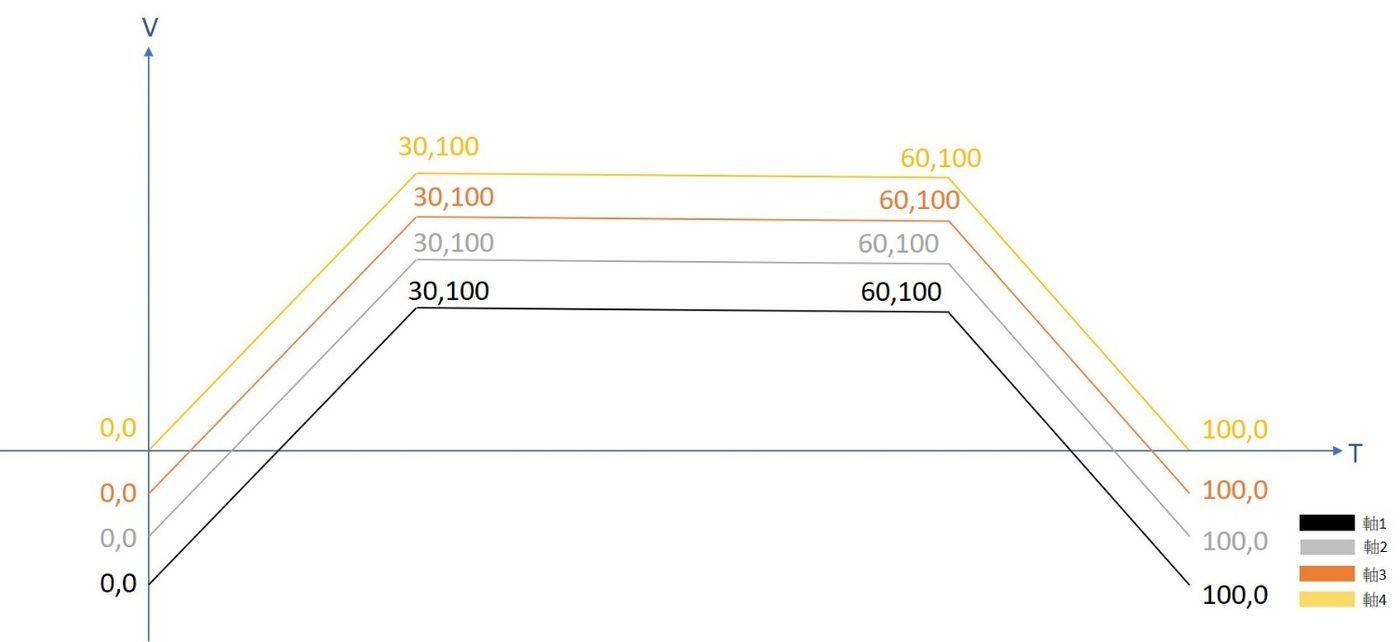
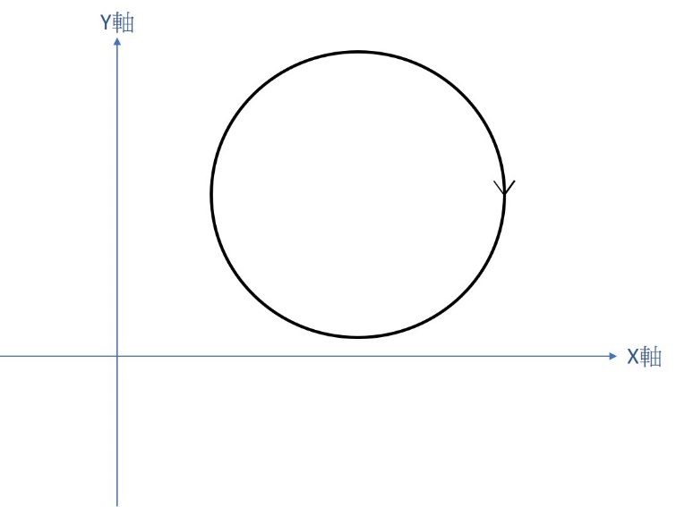
Under Arc Interpolation Mode, it allows the system to execute single linear action on 2 axes.
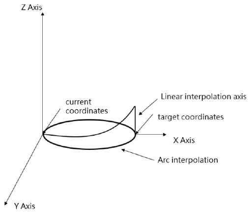
The Spiral Interpolation can run the arc interpolation and then coordinate with Axis-2 required for executing the linear motion so that the motion track will form the spiral shape.
Described below is the type of coordinates system:
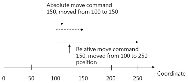
Absolute coordinates:
The target position moved by the designated axis, and it shall be set according to the HOME coordinates. It is the coordinates system established for assigning the number of positions that should be run by the control axis from the HOME coordinates.
Relative coordinates:
The target position moved by the designated axis, and it shall be set according to current coordinates. It is the coordinates system established for assigning the number of positions that should be run by the control axis from current coordinates.
8-5 Linear Interpolation
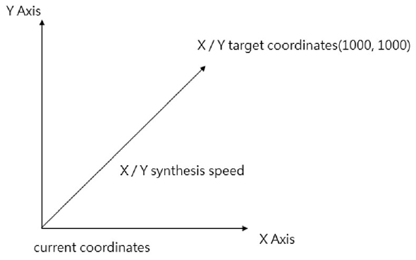
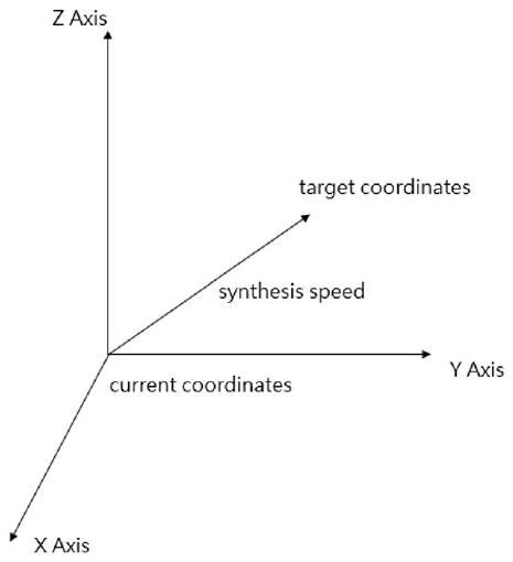
The Linear Interpolation provides maximum 4-axis interpolated motion and it comprises the following two action modes, “linear/position/absolute” and “linear/position/relative” modes. indicated below is the example of Linear Interpolation.
- 2-axis Linear Interpolation
B. 3-axis Linear Interpolation
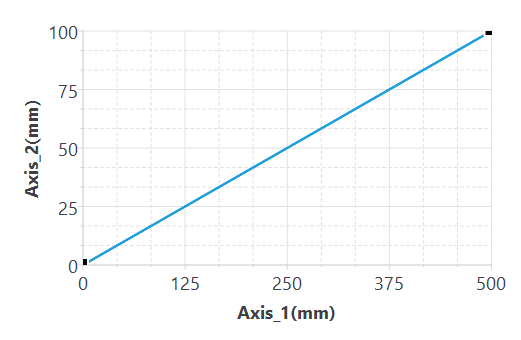
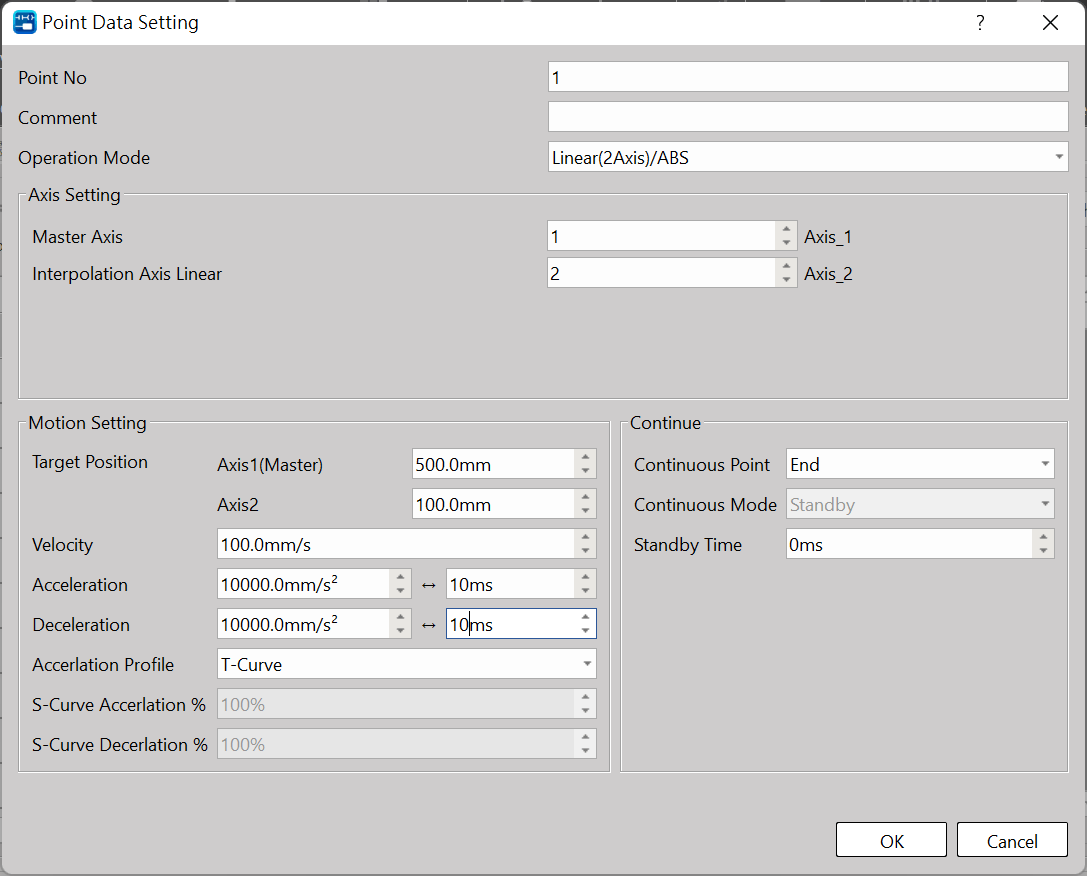
Indicated below is the setting example for 2-axis Absolute Linear Interpolation: Axis_1 is selected as the Master Axis and the axis to be interpolated is Axis_2. The target position Axis_1 is set as 500mm and Axis_2 is set as 100mm. The speed is set as 100 synthesis speed. The acceleration/deceleration behavior is expressed by T-curve and the acceleration/deceleration duration is set as 10ms.
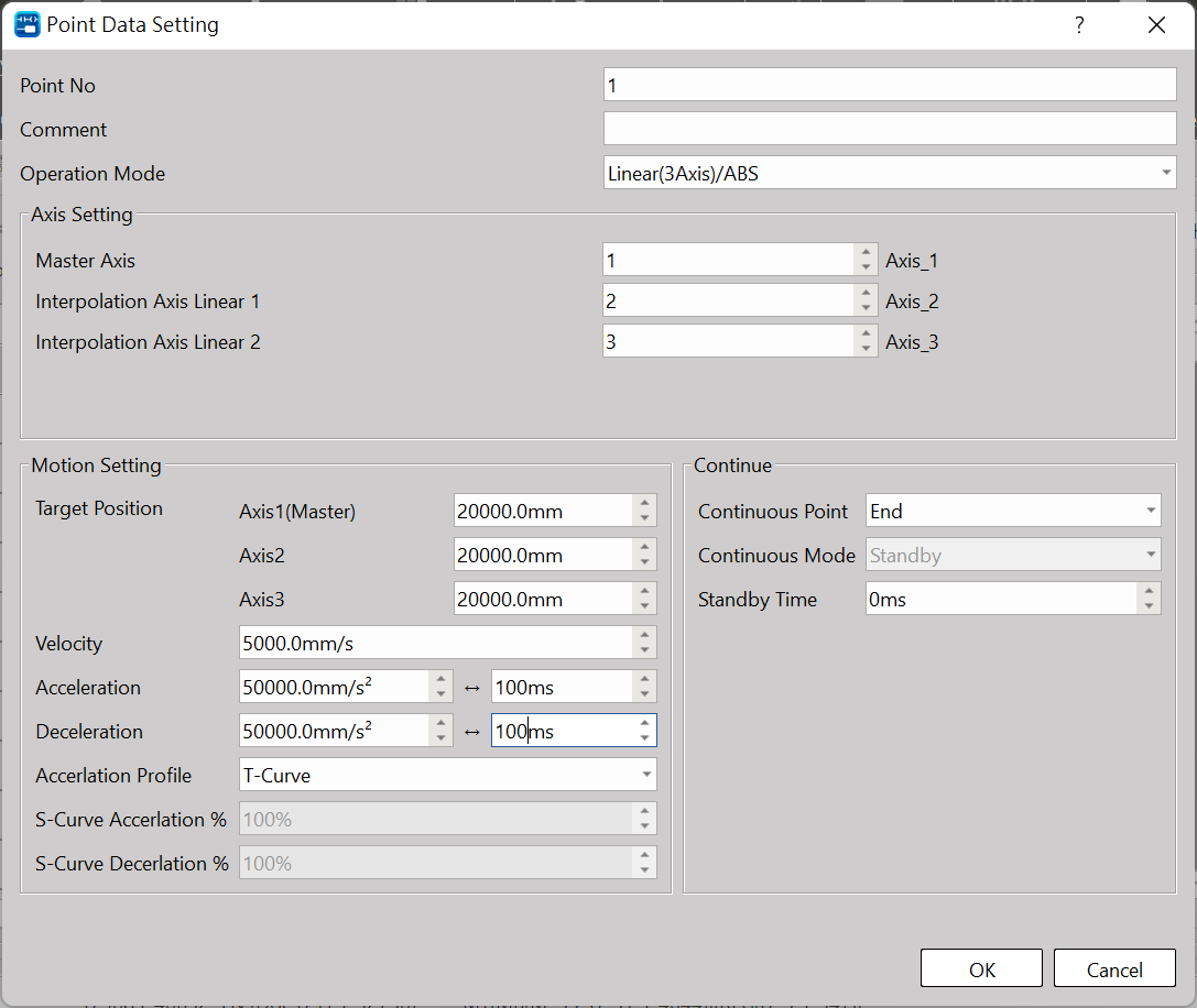
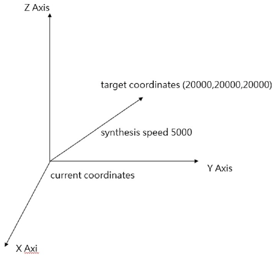
Indicated in the figure is the example showing the setting of 3-axis absolute linear interpolation: Axis_1 is selected as the Master Axis and the interpolated axes to be interpolated are Axis_2 and Axis_3. The target position Axes_1/2/3 are set as 20000 absolute value. The speed is set as 5000 synthesis speed. The acceleration/deceleration behavior is expressed by T-curve and the deceleration duration is set as 100ms.
In this regard, the interpolated Master Axis and the interpolated Slave Axis can be freely organized. For example, selecting Axis_1 as Master Axis, selecting Axis_3 as Linear Interpolation Axis_1, and selecting Axis_5 as Linear Interpolation Axis_2.
The speed and the acceleration/deceleration are expressed as synthesis speed.
The axis without being set with axis link cannot be selected as the interpolation axis.
8-6 Arc Interpolation
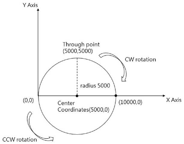
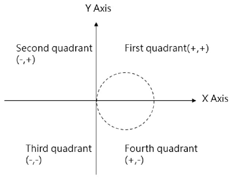
The Arc Interpolation provides maximum 2-axis arc interpolation control and it comprises the following two action modes, “Arc/Position/Absolute” and “Arc/Position/Relative” modes. Described below are the point parameters and setting relating to the arc interpolation running for which three arc appointing methods are provided, and these are through point, center and radius. In this regard, the Master Axis and Slave Axis required for interpolation can be freely organized; for example, selecting Axis_2 as the master axis and selecting Axis_5 as the arc interpolation axis. Indicated below is the circle encompassing Quadrant 1 and Quadrant 4 and its diameter is set as 10000mm. Its radius is 5000mm, center coordinates is expressed as (5000,0) for which, lots of arc through points are also provided.
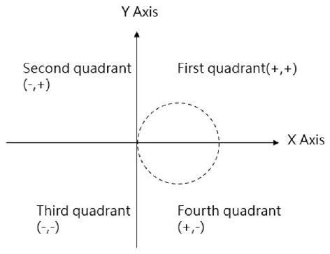
Arc interpolation related parameter setting:
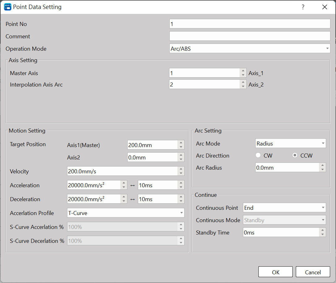
Opearation Mode:
“Arc/Absolute” and “Arc/Relative” modes.
Arc Mode:
Radius, Center Point and Through Point modes.
When designating radius for Arc Mode:
The radius can be designated according to the target position of Master Axis and Interpolation Axis for running one round of arc interpolated motion.
Per the example indicated below:
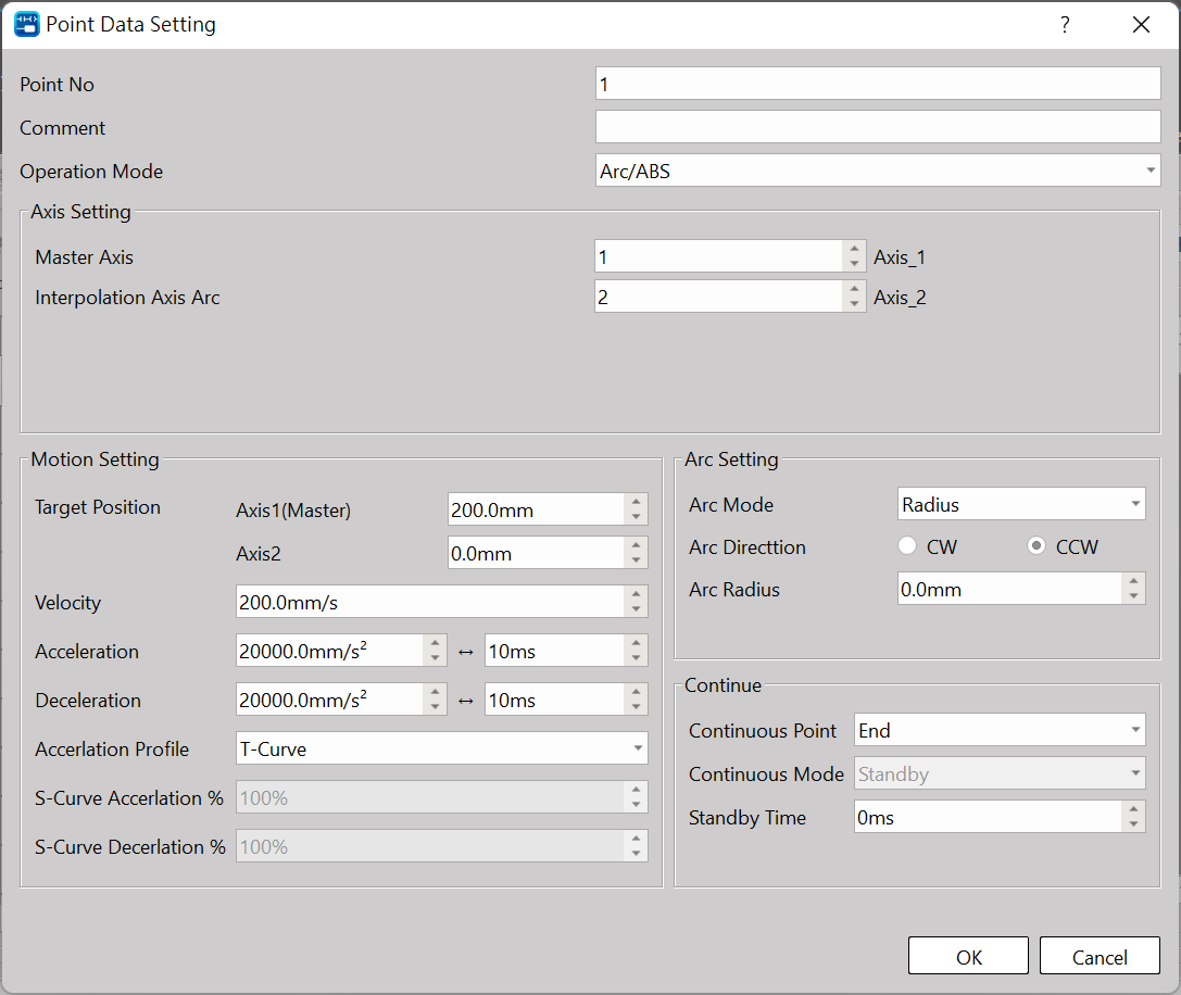
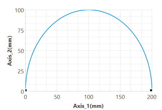 When setting the Arc Mode as the radius, the initial coordinates are set as (0,0), the target position of Axis_1 is set as coordinates 200mm and the target position of Axis_2 is set as coordinates 0mm. The speed is set as 100mm/s and the arc direction is as CW. When setting the arc radius as 100mm, the system will draw a 100mm radius semi-circle on Quadrant-1. When selecting CCW, the system will draw a 100mm radius semi-circle on Quadrant-4. However, an error will appear when the difference between the front coordinates and the target coordinates is over 2 times the radius.
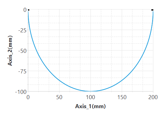
If the arc radius is wrongly set such that the arc cannot be run as intended, then the system will signal the error code before starting the designed motion. Through the point diagram preview function of UperLogic, the user will be allowed to preview the arc path, as below.
When designating Center point for Arc Mode:
By using the target position of the interpolated Master Axis and the interpolation axis as well as designating the center coordinate of the arc, you will be allowed to run the arc interpolated motion. The arc path is the circle formed by using the current coordinates and designated center coordinates as the radius. When setting the circle by using the target coordinates as the arc, you may designate an arc that can rotate for over 180 degrees. If the current coordinates are the same as the target coordinates, then it can be converted to a full-circle arc. You may also designate the “revolution” as 1 in order to rotate over one circle, as per the example provided below:
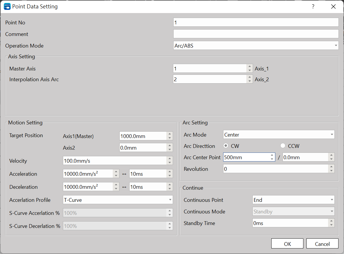
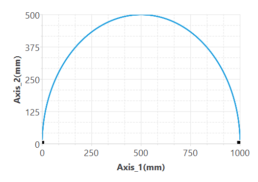
When setting the Arc Mode as the center, the initial coordinates are set as (0,0), the target position of Axis_1 is set as coordinate 1000mm and the target position of Axis_2 is set as coordinate 0mm. The speed is set as 100mm/s and the arc direction is as CW. When setting the arc center point Axis_1 as 500mm and Axis_2 as 0mm, the system will draw a circular arc on Quadrant-1 where the center coordinate is located at (500, 0).
If current coordinate, target coordinate and center coordinate are the same, then the system will signal an error code before starting the designed motion. Through the point diagram preview function of UperLogic, the user will be allowed to preview the arc path, as per below:
When designating Through point for Arc Mode:
By using the target position of the interpolated Master Axis and the interpolation axis as well as designating the pass point coordinate of the arc, you will be allowed to run the arc interpolated motion. The arc path is the circle being formed by starting from the current coordinate and the pass point of the designated arc to the target coordinate. You may designate the arc that can rotate over 180 degrees, but you cannot designate the entire circular arc. If the current coordinate, target coordinate and through point coordinate are the same, then it means an error is present, as per the example indicated below:
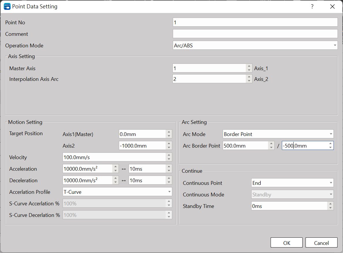
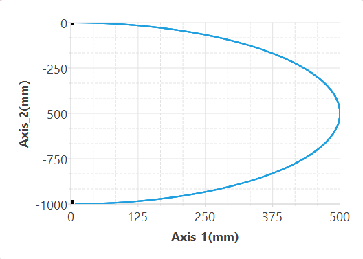
When setting the Arc Mode as the pass point, the initial coordinates are set as (0,0), the target position of Axis_1 is set as coordinate 0mm and the target position of Axis_2 is set as coordinate -1000mm. The speed is as 100mm/s and the arc direction is as CW. When setting the arc pass point Axis_1 as 500mm and Axis_2 as -500mm, the system will draw a circular arc on Quadrant-4 where the center coordinate is located at (500,-500). If the current coordinate, target coordinate and center coordinate are the same, then the system will signal an error code before starting the designed motion. Through the point diagram preview function of UperLogic, the user will be allowed to preview the arc path, as per below:
Arc direction:
CW (Clockwise) and CCW (Counterclockwise)
Continuous Point: Select end or continue next motion point table.
Note: 2D is allowed to continue 2D point action and 1D is allowed to continue 1D point action.
Continue Mode:
Standby: The “ms” duration that should be paused before moving to next point after completing the operation at the current point.
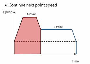
Continue next point speed: Moving to the next point after completing the acceleration or deceleration for such point.
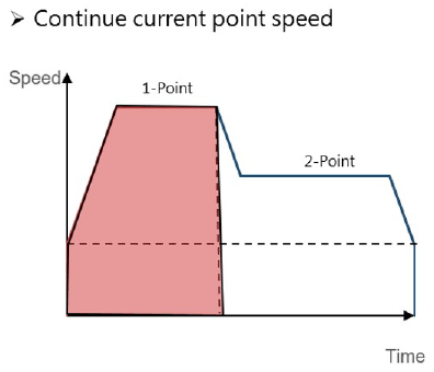
Continue current point speed: Moving to the next point through acceleration or deceleration after completing current speed.
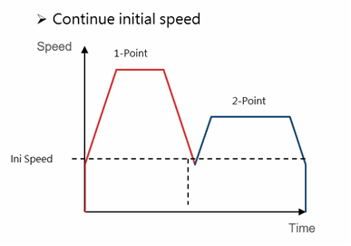
Continue initial speed: Moving to the next point after reducing to the initial speed.
Standby time: The standby time when operating under Standby Mode (unit: ms)
Nimber of round:
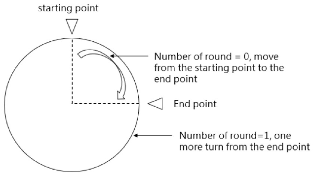
When designating the center point for the arc, the system provides the circle count function. The circle count means the function by drawing another circular arc from the arc interpolated target coordinate to the intended target coordinate. If the starting point is not the same as the ending point, it means the designated circle count will be moved along the arc track from the starting point to ending point. If the starting point is equivalent to the ending point, it means one more circle is executed on top of the designated “nimber of count”.
8-7 Spiral Interpolation
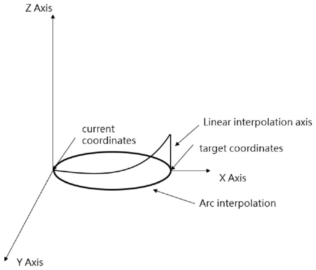
The arc interpolation can be executed on the spiral interpolation. It can be used to coordinate with Axis_3 required for running the linear motion so as to form a spiral shape of moving track. The spiral interpolation comprises the following two action modes, i.e. “Spiral/Position/Absolute” and “Spiral/Position/Relative”. In Spiral Interpolation, the Master Axis and the interpolated Slave Axis can be freely organized.
The spiral interpolation can be used to control all three axes where 2 axes serve as the Master Axis and the Slave Axis during the arc interpolation. While performing arc interpolation, perform interpolation on the linear axis on the third axis for synchronization, and then perform a spiral track motion.
Example:
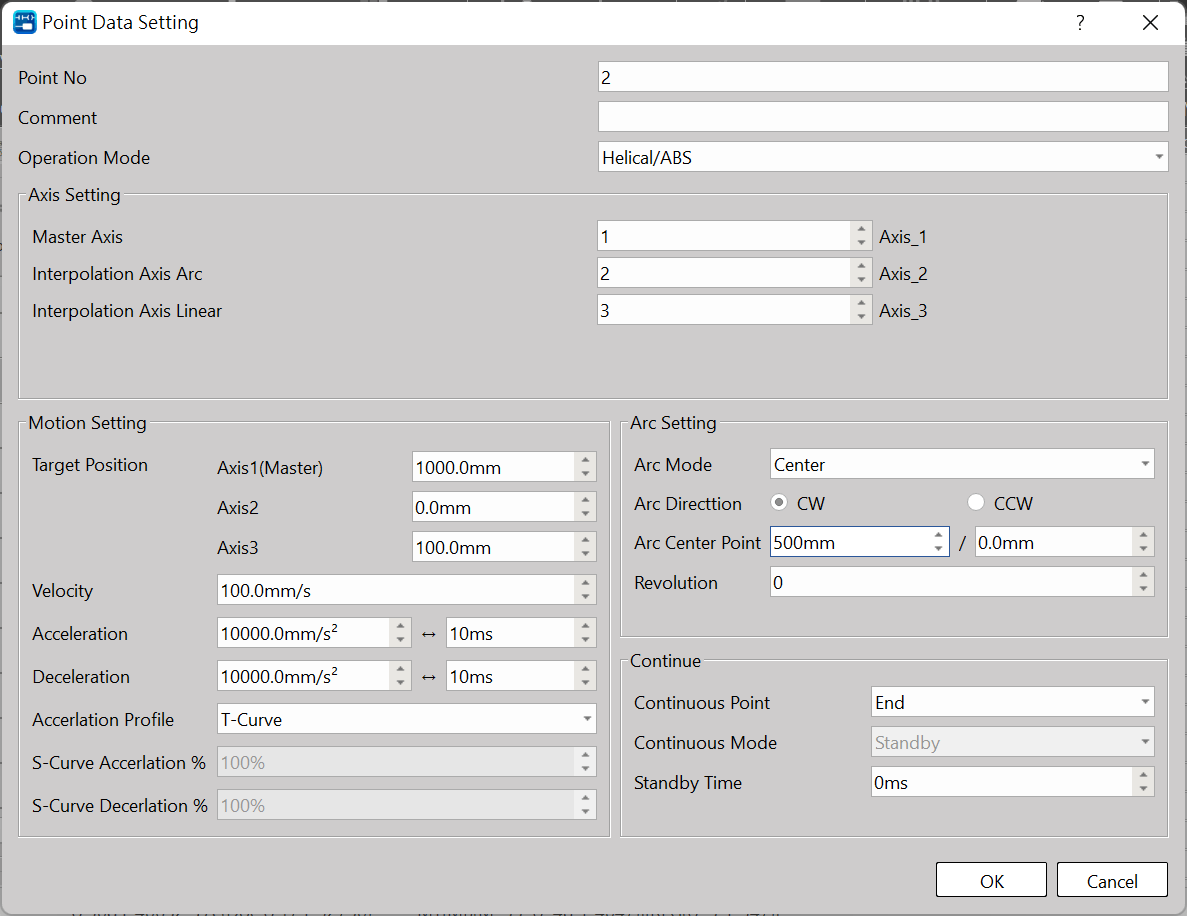
Master Axis is set as Axis_1. Arc interpolated axis is set as Axis_2. Linear interpolated axis is set as Axis_3, and synthesis speed is set as 100mm/s. Arc mode is set as center point, and Axis_1=500mm, Axis_2=0mm. Target position of linear interpolated Axis_3 is set as 100mm.
Tip: press ← → to switch chapters, Ctrl+K to search