Motion Parameter Mapping Table
9-1 Introduction of Motion Parameter Mapping Table
The motion parameter mapping table allows users to dynamically modify motion control related parameters in the PLC Ladder program. Users can dynamically modify related motion parameters in the PLC Ladder program by specifying registers and corresponding to the parameter items to be modified through MFMapTbPrm. At present, the sports parameters are not open to all sports parameters for dynamic modification in the user Ladder. Currently, the modifiable motion parameters are provided in the following table:
|
Motion Parameter Group |
Dynamically Modifiable Item |
Modified Item Position |
|---|---|---|
|
Point Table |
Mode Acceleration Curve Type Position (Master Axis) Position (Slave Axis 1) Position (Slave Axis 2) Position (Slave Axis 3) Speed Acceleration Deceleration S Acceleration Ratio S Deceleration Ratio Arc Mode Arc Direction Arc Point X Arc Point Y Arc Point Radius Auxiliary Radius Standby Time Next Point No. Arc Rounds Continue Mode Arc Point Z Synthesis Rate |
Motion Parameter → Motion Point Setting |
|
Axis Table |
Initial Speed Max. Motor Speed Default Acceleration Default Deceleration Soft Limit (+) Soft Limit (-) Following Error Window Following Error Timeout Positioning Completion Tolerance Positioning Completion Check Time Max. Motor Torque Max. Torque Limit (+) Max. Torque Limit (-) HOME Mode HOME Return Direction HOME Return Offset HOME Return Searching Speed HOME Return Crawling Speed JOG Initial Speed JOG Speed JOG Acceleration JOG Deceleration JOG Distance |
Motion Control → Motion Axis Setting |
|
Synchronous Table |
Clutch OFF sliding time at deceleration time Master Axis Phase Compensation: Compensation Instruction Amount Master Axis Phase Compensation: Compensation Change Mode Master Axis Phase Compensation: Compensation Change Time Auxiliary Axis Phase Compensation: Compensation Command Amount Auxiliary Axis Phase Compensation: Compensation Change Mode Auxiliary Axis Phase Compensation: Compensation Change Time Variable Gear Ratio Numerator Variable Gear Ratio Denominator Variable Gear Ratio Change Mode Variable Gear Ratio Change Time Clutch ON Setting Value Clutch ON Delay Main Clutch: Clutch ON Offset Main Clutch: Clutch ON Offset Time Main Clutch: Clutch ON Following Time Main Clutch: Clutch ON Following Offset Main clutch: Clutch OFF Setting Value Main Clutch: Clutch OFF Delay Main Clutch: Clutch OFF Offset Main Clutch: Clutch OFF Offset Time Auxiliary Clutch: Clutch ON Setting Value Auxiliary clutch: Clutch OFF delay Auxiliary Clutch: Clutch OFF Offset Auxiliary Clutch: Clutch OFF Offset Time Reserve 1 (Do not use) Reserve 2 (Do not use) Step Angle Compensation: Reference Speed Step angle compensation: reference amount Step Angle Compensation: Compensation Value Change Method Step Angle Compensation: Compensation Value Change Time Cam Profile No. Synchronization Contact No. Output Filter Time Constant Cam Input Cycle Synchronous Master Axis Phase Default Value Master Axis Phase Default Value after Phase Compensation Main Clutch Input Phase Default Value Auxiliary Clutch Input Phase Default Value Main Clutch Output Axis Phase Default Value Auxiliary Clutch Output Axis Phase Default Value Torque Limiting Clutch Input Axis Phase Default Value Cam Input Axis Phase Default Value Cam Output Axis Reference Coordinates Cam Travel |
Motion Control → Motion Synchronizing Setting → Synchronizing Parameters |
|
Axis Speed |
Speed Max. Torque |
The speed and torque limit of the current control mode of the axis in “Speed Mode” |
|
Axis Torque |
Torque Max. Speed |
The speed and torque limit of the current control mode of the axis in “Torque Mode” |
|
Synchronous Contacts |
Output Position ON Setting Value OFF Setting Value |
Motion Control → Motion Synchronizing Setting → Synchronizing Contacts |
|
Internal Motion Variables |
MW |
Motion Control → Motion Flow, Dedicated internal register within the motion flow |
|
Flow Block |
Syandby Flow Block – Waiting Time |
Motion Control → Motion Flow → Standby Flow Block → Waiting Time |
|
Positioning Block – Axis 1 Change Value Positioning Block – Axis 2 Change Value Positioning Block – Axis 3 Change Value Positioning Block – Axis 4 Change Value Positioning Block – Axis 5 Change Value Positioning Block – Axis 6 Change Value Positioning Block – Axis 7 Change Value Positioning Block – Axis 8 Change Value Positioning Block – Axis 9 Change Value Positioning Block – Axis 10 Change Value Positioning Block – Axis 11 Change Value Positioning Block – Axis 12 Change Value Positioning Block – Axis 13 Change Value Positioning Block – Axis 14 Change Value Positioning Block – Axis 15 Change Value Positioning Block – Axis 16 Change Value |
運動控制 → 運動流程 → 定位控制流程塊 → 更改行為 : 改變當前座標、改變目標位置、中斷定長以及中斷定角 → 軸 1 到軸 16 更改值 |
|
|
Positioning Block – Change Speed |
Motion Control → Motion Flow → Position Control Flow Block → Change Behavior: Speed Change → Changed Value |
|
|
Positionig Block – Change Behavior |
Motion Control → Motion Flow → Position Control Flow Block → Change Behavior |
Uperlogic Motion Parameter Mapping Table is shown below:
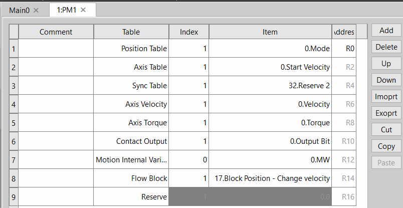
Mapping table operation bit usage timing:
1. When the FUN198 MFMapTbPrm mapping table writing command is triggered by the rising edge, it will write the value in the R register set by the PLC into the table corresponding to MOTION, and output the DN signal after the writing is completed. Once writing, the command must be reset first, and then perform the same action.
2. Please pay attention to the timing of writing and calling the motion control table data. The mapping table writing command can be used at any time and will be written into the motion control table immediately. The timing of calling the motion control table data is divided into Immediate Effect and Effective on First Entry. There are two types of effect, immediate effect means that the current value is directly overwritten during the call, and the effect when entering for the first time means that the value already in the call will not be overwritten, so it will not take effect until the next call. Please see table below for the timing of data call in different control modes :
|
Motion Control Parameter Table |
Control Mode |
Call Timing |
|---|---|---|
|
Point Table |
Position Control Mode |
Effective on First Entry |
|
Axis Table |
Arbitrarily Control Mode |
Effective on First Entry |
|
Synchronous Table |
Syncgronous Control Mode |
Immediate Effect |
|
Axis Speed |
Speed Control Mode |
Immediate Effect |
|
Axis Torque |
Torque Control Mode |
Immediate Effect |
|
Synchronous Contacts |
Sychronous Control Mode |
Immediate Effect |
|
Internal Variables |
Arbitrarily Control Mode |
Immediate Effect |
|
Flow Block |
Arbitrarily Control Mode |
Immediate Effect |
* : In synchronous mode, the axis special relay can decide to take effect immediately or in the next synchronous cycle.
9-2 Motion Parameter Mapping Table Using Method
Provided below is the Motion Parameter Mapping Table using method;
|
No. |
Action |
Remark |
|
1 |
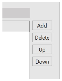
Click “Add” in Motion Parameter Mapping Table. |
|
|
2 |
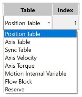
Select motion parameter group Point table/axis table/or synchronization table |
|
|
3 |
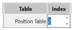
Select index When the Point Table index is the desired No. xx Point motion parameter When the Axis Table index is the desired No. xx Axis parameter When the Synchronization Table index is the No. xx axis parameter |
|
|
4 |
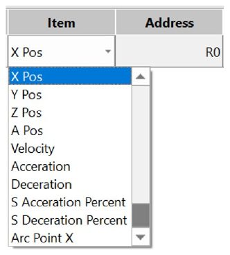
Select the item Each motion parameter group contains its own motion parameters |
|
|
5 |
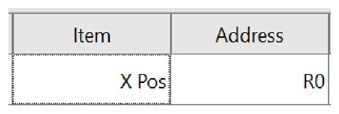
Designate address R |
|
|
6 |
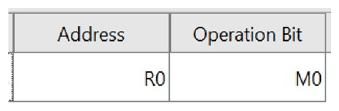
The designated initial bit required for the operating bit shall be a multiple of “8”. |
|
|
7 |
Write the value to be changed in “R”. |
Bigger value will occupy 2 units of “R”. |
|
8 |
By turning on the operating bit, the PLC program will write the designated motion parameter in R. |
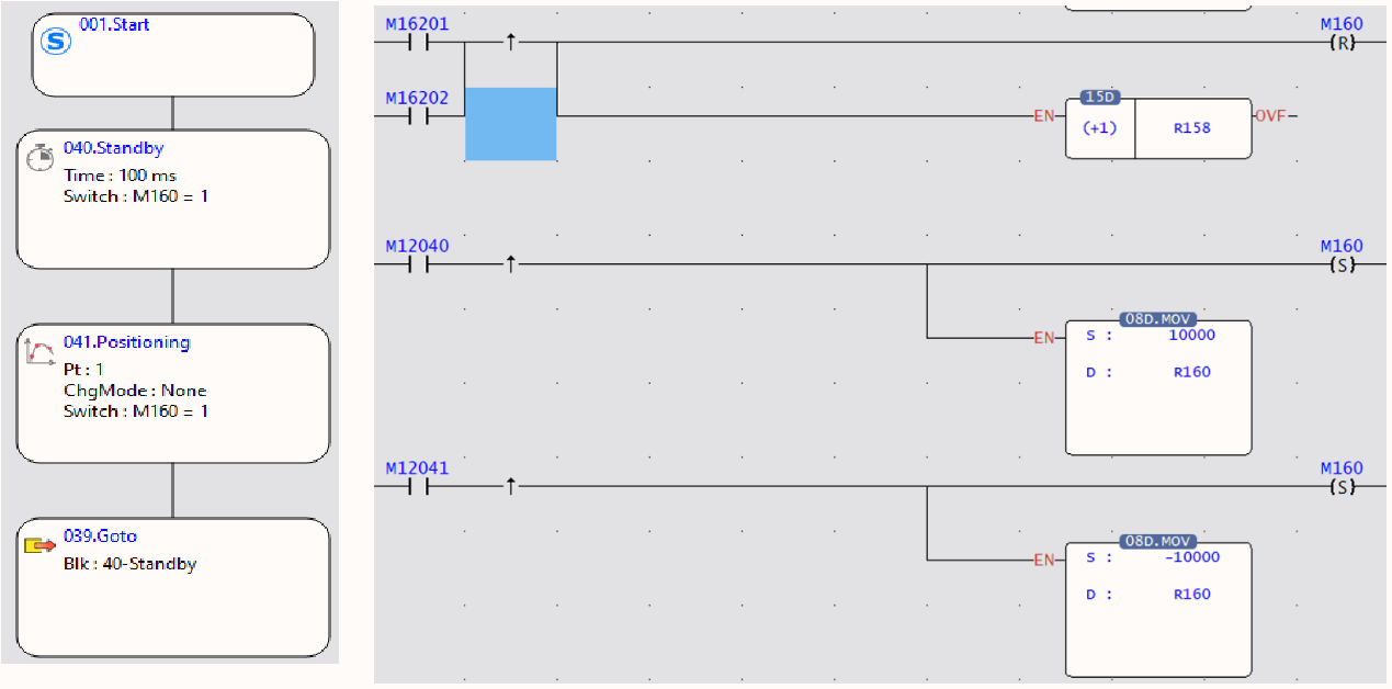
Ladder program example:
Block status signal M16000: 000= 160+block number
Block end signal M12000: 000= block number
M160 = Operating bit
R160 = Mapping address
1. When Flow begins and when PLC reads M16021 is ON, it will run the initialization for M160 OFF.
2. When Flow is under standby and when PLC reads M12040, it will execute M160 ON and then write “10000” value in R160 (mapping address).
3. When Flow executes the positioning control and when PLC reads M12041, it will execute M160 ON and then write “-10000” value in R160 (mapping address).
9-3 Precautions for Use
Description of instructions on using the Motion Parameter Mapping Table:
1. In the Motion Parameter Table, the operating bit and the address user needs to designate the first position only and the rest will be arranged by the system automatically.
2. If the axis is moving when changing the motion command, such as position and speed, then the parameters in the Motion Point Table will remain unchanged. The motion mapping change won’t become effective until the next round of motion after stopping the current motion.
3. If the Motion Synchronization Table has been changed, the mapping parameter can be used after being included even though the synchronous control is executed by the system at that time.
4. Reminder: If the “R” designated by the mapping parameter is set as shutdown non-holding type, then “R” will become zero after restarting the PLC. If the user wishes to hold the mapping parameter “R” after restarting the PLC, please set it as the shutdown holding type.
5. When writing the mapping parameter in PLC Ladder, such action should be executed according to “motion control flow block end signal” and “motion control flow block running signal”.
|
Motion control flow block end signal |
M12000 + block number |
0: Standby 1: Flow block running done * Set at “OFF” when running such flow block next time. |
Read Only |
|
Motion control flow block running signal |
M16160 + block number |
0: Flow block is not running 1: Flow block is running |
Read Only |
Tip: press ← → to switch chapters, Ctrl+K to search