【PLC Integration】provides designers or users in pratical applications of HMI and PLC to achieve closer integration. For example, in practical applications users can show or view the current connection of WinProladder through HMI, no need to link PLC to PC to view Ladder diagram program of WinProladder, let users easy to use and debug.
Currently 【PLC Integration】includes【Show Ladder Viewer】,【Update FATEK PLC Project From USB】,【Show Ethernet Module Configuration】
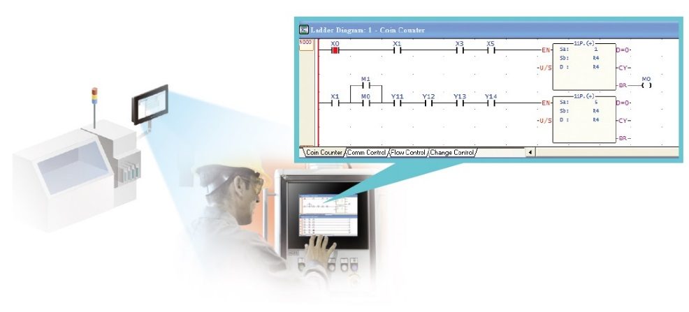
Figure 505 HMI show PLC Ladder Diagram Program illustration
27.1 Show Ladder Viewer
This section will explain how to show Ladder Diagram Program of PLC (FATEK PLC) on HMI and show the interface of PLC Ladder Diagram Program which includes the meaning of options and settings.
Note 1 : The 4.3-inch HMI does not support the display of the Ladder Viewer function, such as P5043S or P5043N.
Note 2 : FATEK FBe PLC does not support
27.1.1 【Show Ladder Viewer】Applications and Settings
For example, use FATEK P5 series HMI connted with FATEK FBs series PLC, and hope in the P5 series HMI display and view the FBs series PLC ladder diagram program, Set the following steps:
Step 1:【Toolbox】【Lamp/Switch】drag a【Function Switch】to windows,as shown below.
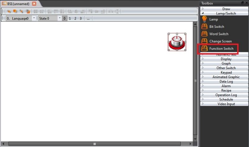
Figure 506 drag a【Function Switch】to window
Step 2: double click Function Switch to enter Function Switch Properties, and in this dialog window by the "function" drop-down menu, select 【PLC: Show ladder viewer】, as shown below.
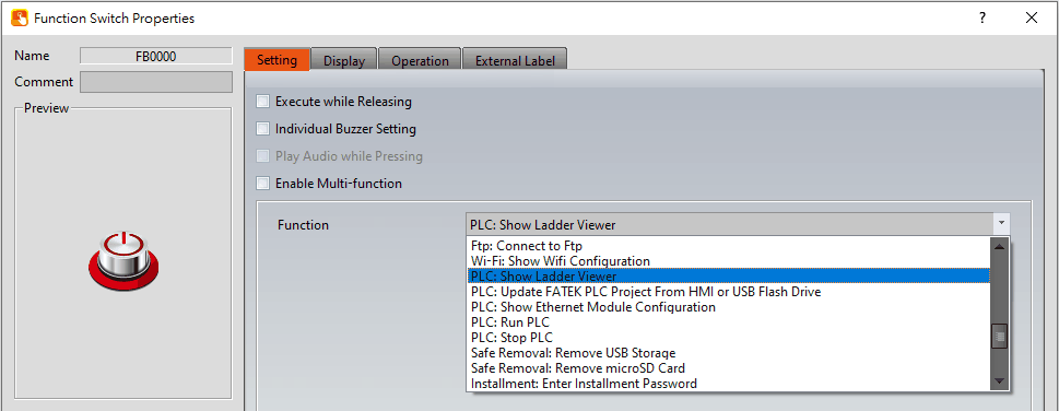
Figure 507 select【PLC: Show ladder viewer】dialog
Step 3: set the connection of HMI and PLC, then compile and download to HMI, through the connection, press the 【Function Switch】【PLC: Show ladder viewer】, will appear link device dialog, as show below, the device name is the name of the device in the software link setting.
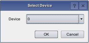
Figure 508 The menu dialog of the linked device
Note: in off-line simulation, press【Function Switch】will not appear link device dialog, but will appear in HMI interface, microSD or USB storage devices, choose the PLC project(*.pdw) loading dialog window.
Step 4: choose the device, then it will load the PLC ladder diagram program, as shown below.
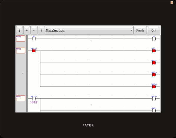
Figure 509 show PLC ladder diagram program
27.1.2 HMI display the interface of PLC ladder diagram program
The interface of the PLC ladder program is displayed on the HMI, as shown below.
The meaning of each settings, as shown in the table below.
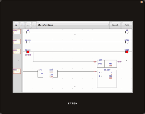
Figure 510 The interface of the PLC ladder diagram is displayed on the HMI
Table 296 shows the attributes of the PLC ladder diagram interface on the HMI
|
Property |
Description |
|
【Display Settings】 |
Press this icon
|
|
【Comment】 |
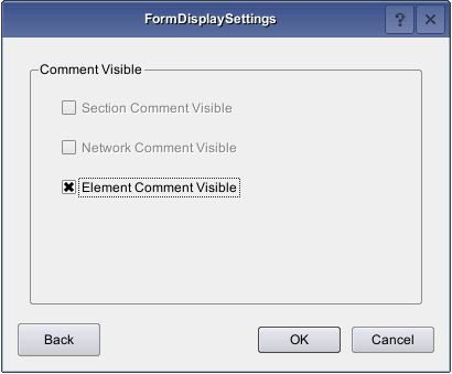
【Comment】 Click on the box that says “Comment” and the following dialog window will pop up, as show below.
【Comment Visible】 Set whether the comments in the ladder diagram are displayed. 【Section Comment Visible】 Set whether the program area comments in the ladder program is displayed. The current preset is disabled and cannot be checked. 【Network Comment Visible】 Set whether the network comment in the ladder program is displayed. The current preset is disabled and cannot be checked. 【Element Comment Visible】 Set whether the element comment in the ladder program is displayed. |
|
【Language】 |
【Language】 In this window, you can select the language of your comments in the ladder program. Languages include English, Traditional Chinese, Simplified Chinese, Other Language, and so on. Selectable languages should be added from【Font Library】.
|
|
【Block Open/ Close】 |
This option is mainly for the WinProLadder block close and block open function(Need to cooperate with Fun199). Click on the button and the following dialog window will pop up, the HMI will activity to search the ladder diagram that those networks are block closed then list it, operators can choose which networks are open or close(If the original close block has a set password, need to enter password to open the block password), press OK to see ladder diagram.
|
|
【Reload】 |
【Reload】 Reload the ladder program. |
|
【Zoom in】 |
Press this icon |
|
【Zoom out】 |
Press this icon |
|
【PLC Status Information】 |
Press this icon
|
|
【Switch between the MainSection and the SubSection program】 |
Press this icon |
|
【Search】 |
Press this icon
【Find】 Search type and address. 【Goto】 Can jump to host program or subprogram network number
【Register Type/Network Number】 Enter the type and address you want to search for or jump to the host or subprogram network number 【Filter】 Filter the type of search, including contacts, coils, functional instructions, and all, etc. 【Start Position】 Start position, including automatic and current location. 【Searching Direction】 Searching Direction, including move up and move down, etc. |
|
【Quit the ladder diagram window】 |
Press this icon |
|
【Move up】 |
Press this icon |
|
【Move down】 |
Press this icon |
|
【Move right】 |
Press this icon |
|
【Move left】 |
Press this icon |
|
【Network No.】 |
This icon |
 , will display the settings dialog window, as shown below.
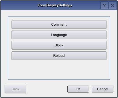
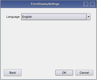
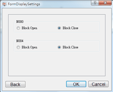
 , will zoom in on the HMI ladder diagram.
 , will zoom out on the HMI ladder diagram.
 , will pop up PLC status information window, as shown below.
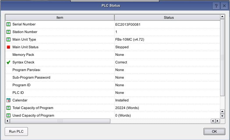
 , switch between the MainSection and the SubSection program.
 , the dialog window for the address search will pop up, as shown below.
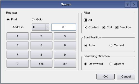
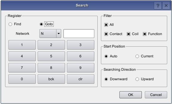
 , will quit the ladder diagram window.
 , the ladder diagram will be viewed above.
 , the ladder diagram will be viewed below.
 , the ladder diagram will be viewed right.
 , the ladder diagram will be viewed left.
 is Network No. for the ladder diagram.
27.2 Update FATEK PLC Project From HMI or USB Flash Drive
This section explains how to update the ladder program of a connected PLC using the HMI’s internal storage or a USB storage device.
Step 1:
Select【PLC: Update FATEK PLC Project From HMI or USB Flash Drive】from the 【Function Switch】in FvDesigner.
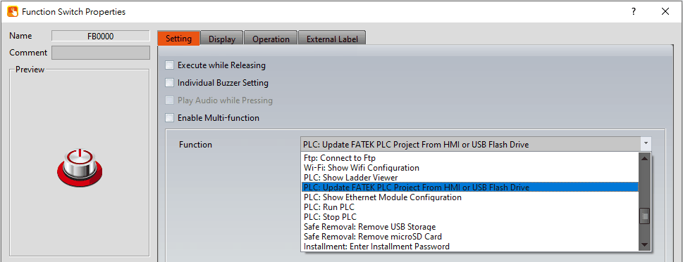
Figure 511 Update PLC program step 1
Step 2:
Place the PLC program in the HMI internal storage or on a USB flash drive. After pressing the function button in the project, you can select the PLC program you want to download. The software will display the corresponding device according to the selected file (for example, if a .pdw file is selected, only FBs series PLCs can be chosen). After that, the download process can begin.
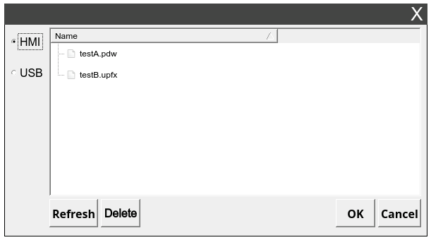
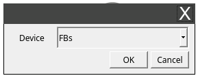
Figure 512 Update PLC program step 2
The following explains how to obtain programs for FBs and MPLC series.
FBs Series – WinProladder
When saving the file in WinProladder, select【Project file】to generate the【.pdw】file.
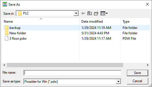
Figure 513 How to get pdw file
MPLC Series – UperLogic (Supported in FvDesigner v1.6.83 / v1.7.07 or later, and UperLogic v1.0.10 or later)
When saving the file in UperLogic, select Export UperLogic Pack File, and check the parameter Use for FATEK HMI.
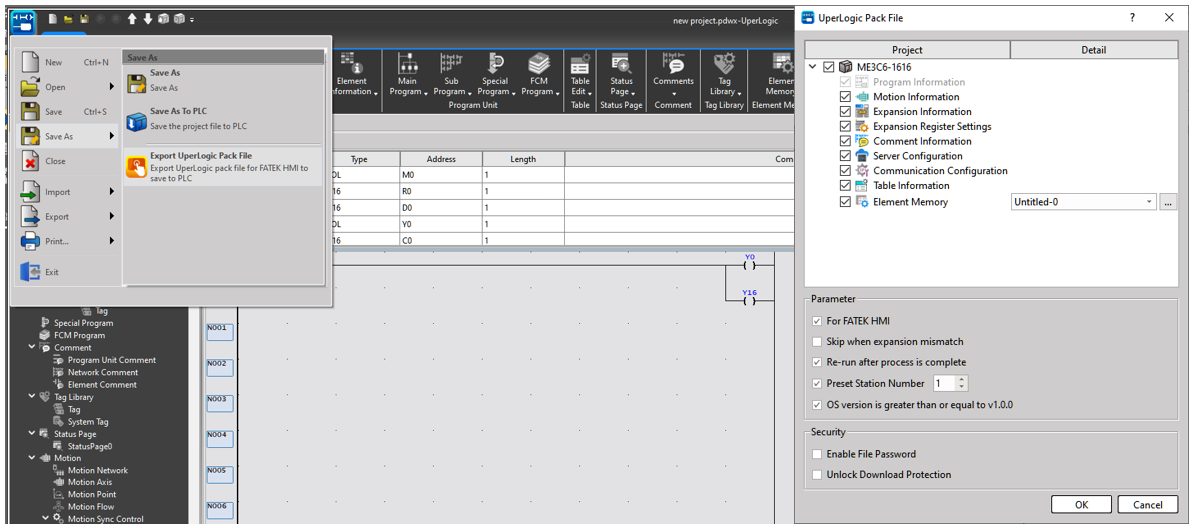
Figure 514 How to get upfx file
※Notice: When running in【.pdwOffline Simulation】, pressing this function will have no effect.
27.3 【FATEK PLC Transfer Encrypt Tool】
This chapter explains how to use the USB storage device of HMI to update the connected FATEK PLC ladder diagram program, how to protect the operation flow, and protect the designer’s planned PLC ladder diagram program and intellectual property, etc.
Use the USB storage device of HMI to update the connected FATEK PLC ladder diagram program divide it into 2 parts.
The first part, if you do not need to protect the PLC project, you can directly copy the PLC project (*.pdw) planned by FATEK PLC software to the USB storage device, microSD card, or through FTP function transfer the PLC project to the HMI internal storage, and follow-up will be able to update the FATEK PLC project according to chapter 0-
Update FATEK PLC Project From HMI or USB .
In the second part, if the PLC project needs to be protected, it is necessary to follow the follow-up instructions to generate the designer’s all transfer password or single pass password and conversion file, etc., so that the designer’s planned PLC ladder diagram program can be protected. The following describes how to set and use transfer passwords, single passwords, and conversion files.
27.3.1 【FATEK PLC Transfer Project Generator】
This chapter will explain how to use the USB storage device HMI to update the connected FATEK PLC ladder diagram program, and the PLC project needs to be protected. How to set the【Transfer Password】and convert the file, etc. This can be achieved through the【FATEK PLC Transfer Encrypt Tool】provided by FvDesigner.
If only set【Transfer Password】, it’s available for unlimited downloads, in other words, you can update the connected FATEK PLC ladder diagram program for an unlimited number of times.
【FATEK PLC Transfer Project Generator】can be found on the Tools tab on the FvDesigner ribbon, after select the【FATEK PLC Transfer Encrypt Tool】drop-down menu then click【FATEK PLC Transfer Project Generator】options to do the setting.
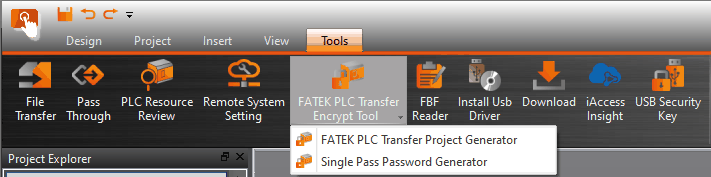
Figure 515【FATEK PLC Transfer Project Generator】option
The【FATEK PLC Transfer Project Generator】page is shown in the figure below. The meaning of each setting option is as follows:
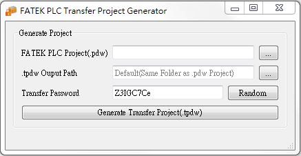
Figure 516【FATEK PLC Transfer Project Generator】setting
Table 297【FATEK PLC Transfer Project Generator】properties setting
|
Properties |
Description |
|
【Generate Project】 |
With this tool, you can convert the original FATEK PLC project (*.pdw) into an encrypted file *.tpdw and generate all the transfer passwords for the designer. 【FATEK PLC Project(.pdw)】 Set the path and file location of the original FATEK PLC project (*.pdw). 【.tpdw Output Path】 Set the path of *.tpdw to be generated. If it is not set, the default path is same as the original FATEK PLC project (*.pdw), and the converted files can no longer be opened with FATEK PLC’s software WinProLadder. 【Transfer Password】 The transfer password generated by the system can update to the connected FATEK PLC ladder diagram program for an unlimited number of times. 【Random】 After pressing this button, the system will provide a new set of transfer passwords again. 【Generate Transfer Project(.tpdw)】 Press this button to generate *.tpdw file and save it in the set path. |
After setting the transfer password, you can update the FATEK PLC project according to the chapter0-
Update FATEK PLC Project From HMI or USB , but when selecting the FATEK PLC project, select the *.tpdw file, as shown below.
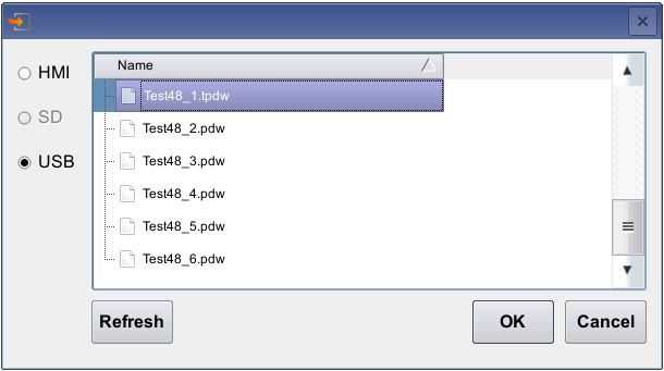
Figure 517 select to update the PLC project
Select the file, press OK, it will display ‘’Please enter password’’ dialogue window, as shown below, please enter the transfer password.
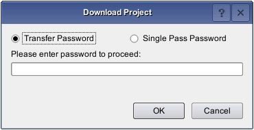
Figure 518 select the transfer password
After entering the transfer password, press OK, the ‘’Select Device’’ dialog window will appear, as shown below.
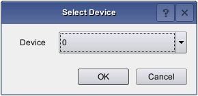
Figure 519 select device
If the PLC wants to download the PLC program during operation, it will first ask whether to stop the PLC operation first, and then continue to update the dialogue window of the PLC program, as shown below.
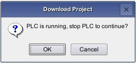
Figure 520 ask whether to stop the running PLC
After finish updating the PLC project, there will be a dialogue window to start the PLC, as shown below.
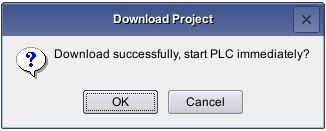
Figure 521 download success and ask whether to start PLC immediately
27.3.2 【Single Pass Password Generator】
The chapter will explain how to set【Single Pass Password】,【Single Pass Password】can only be used once. The user will generate a set of passwords from the HMI due to the operation and provide it to the designer. The designer then generates new password through the【Single Pass Password Generator】to enter to the HMI to update the connected FATEK PLC Ladder Diagram program.
【Single Pass Password Generator】function can be selected in【Tools】function tab on the FvDesigner ribbon, select【Fatek PLC Transfer Encrypt Tool】drop-down menu, and click【Single Pass Password Generator】option to open function setting window.
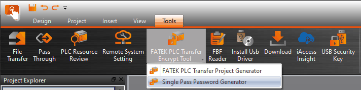
Figure 522【Single Pass Password Generator】option
The【Single Pass Password Generator】page is shown in the following figure. The meaning of each setting option is as follows:
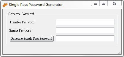
Figure 523【Single Pass Password Generator】setting window
Table 298【Single Pass Password Generator】properties setting
|
Properties |
Description |
|
【Generate Password】 |
Single pass password can be generated through this tool. 【Transfer Password】 Enter the original transfer password. 【Single Pass Key】 Enter the single pass key generated from the HMI. 【Generate Single Pass Password】 Pressing this button will generate a single pass password, which will be provided to the user for input to the HMI to update the connected FATEK PLC Ladder diagram program. |
After setting the transfer password, you can update the FATEK PLC project according to the chapter 0-
Update FATEK PLC Project From HMI or USB, but when selecting the FATEK PLC project, select the *.tpdw file, as shown below.
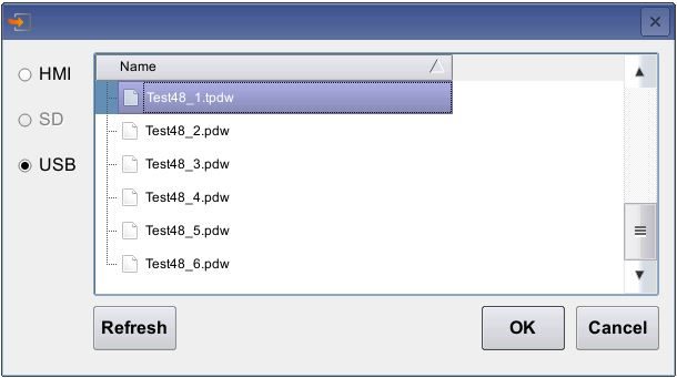
Figure 524 select to update the PLC project
Select the file, press OK, the dialog box for entering the transfer password will be displayed, and click【Single Pass Password】, as shown below.
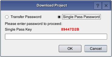
Figure 525 select single pass password
Provide the【Single Pass Key】to the designer. After the designer enters【Transfer Password】and【Single Pass Key】in【Single Pass Password Generator】, press【Generator Single Pass Password】as shown in the figure below.
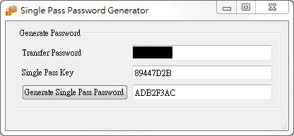
Figure 526【Single Pass Password Generator】window
The generated【Single Pass Password】provide to user to enter to the HMI, as shown in the figure below.
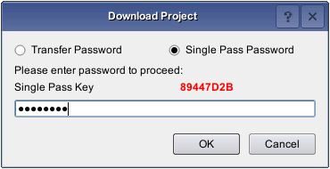
Figure 527 enter single pass password window
After entering the single pass password, press OK, the ‘’Select Device’’ dialog window will appear, as shown below.
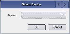
Figure 528 select device
If the PLC wants to download the PLC program during operation, it will first ask whether to stop the PLC operation first, and then continue to update the dialogue window of the PLC program, as shown below.
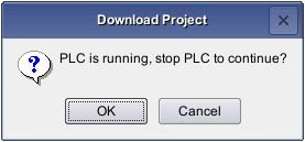
Figure 529 ask whether to stop the running PLC
After finish updating the PLC project, there will be a dialogue window to start the PLC, as shown below.
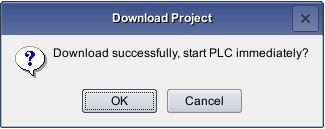
Figure 530 download success and ask whether to start PLC immediately
27.4 Show Ethernet Module Configuration
This section will explain how to set up the ethernet module configuration and options and settings of FATEK PLC on the HMI display ethernet so that the user can easily use it.
27.4.1 【Ethernet Module Configuration】Application and Settings
For example, use FATEK P5 series HMI, Show Ethernet Module Configuration, Set the following steps:
Step 1: 【Toolbox】【Lamp/Switch】drag a【Function Switch】to windows,as shown below.
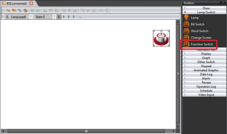
Figure 531 drag a【Function Switch】to window
Step 2: double click Function Switch to enter Function Switch Properties, and in this dialog window by the "function" drop-down menu, select 【PLC: Show Ethernet Module Configuration】, as shown below.
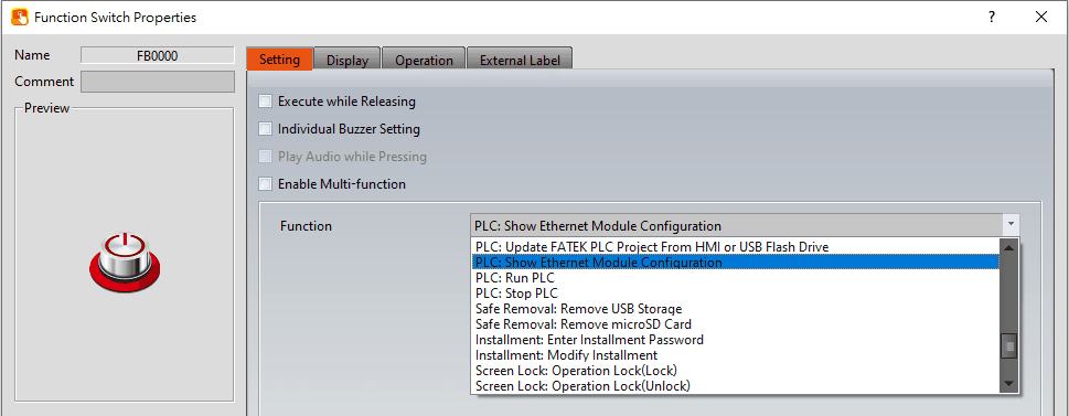
Figure 532 select【PLC: Show Ethernet Module Configuration】dialog
Step 3: set the connection of HMI and PLC, then compile and download to HMI.
Step 4: In the HMI and PLC connection operation, press【Function Switch】【PLC: Show Ethernet Module Configuration】, a dialog window appears to update the PLC project, as shown below.
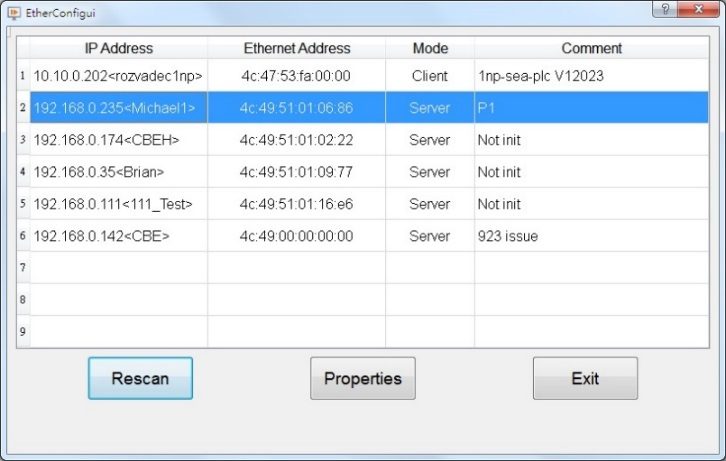
Figure 533 dialog of FATEK PLC on ethernet
Note: after pressing the【Function Switch】, as a result of the search on the network FATEK PLC network module will be delayed some time.
Table 299 properties of FATEK PLC ethernet configuration dialog
|
Options |
Description |
|
【IP Address】 |
IP Address of ethernet configuration |
|
【Ethernet Address】 |
Ethernet Address of ethernet configuration |
|
【Mode】 |
Mode of ethernet configuration |
|
【Comment】 |
Annotations can be used to specify more detailed module information, up to 21 characters. |
|
【Rescan】 |
Rescan ethernet configuration on line, the detected module will be displayed in the middle of the window. |
|
【Properties】 |
Touch to display or set the module data, press this button to enter the module configuration window. |
|
【Exit】 |
Exit the dialog of ethenet configuration. |
27.4.2 General Settings of Ethernet Module
General properties of ethernet module on HMI, as shown below.
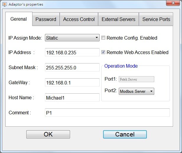
Figure 534 General properties of ethernet module
Table 300 properties of ethernet module settings
|
Optios |
Description |
|
【IP Assign Mode】 |
IP Assign Mode, including static and dynamic and acquisition by the registor of PLC |
|
【IP Address】 |
IP Address of ethernet module. |
|
【Subnet Mask】 |
Subnet Mask of ethernet module. |
|
【GateWay】 |
GateWay of ethernet module. |
|
【Host Name】 |
Host Name, can be used to identify different module. |
|
【Comment】 |
Annotations can be used to specify more detailed module information, up to 21 characters. |
|
【Remote Config Enabled】 |
Check to allow Ether_Config settings to be made remotely via the Internet. |
|
【Remote Web Access Enabled】 |
Check to allow remote through the Internet for Web pages operation. |
|
【Operation Mode】 |
Port1 is fixed to FATEK Server, Port2 can select the working mode according to the demand |
27.4.3 Password Setting Page of Ethernet Module
Display password setting page of ethernet module on HMI, as shown below.
The meaning of each option is as follows, as shown in the following table, please refer to the PLC network Ethernet communication module operating instructions manual
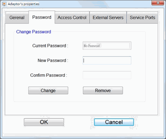
Figure 535 password setting page of ethernet module
Table 301 properties of password setting page of ethernet module
|
Options |
Description |
|
【New Password】 |
To change the new password. |
|
【Confirm Password】 |
Confirm new password. |
|
【Change】 |
Press this button will complete the change setting. |
|
【Remove】 |
Cancle the password. |
27.4.4 Access Control Setting Page of Ethernet Module
Display access control setting page of ethernet module on HMI, as shown below.
The meaning of each option is as follows, as shown in the following table, please refer to the PLC network Ethernet communication module operating instructions manual
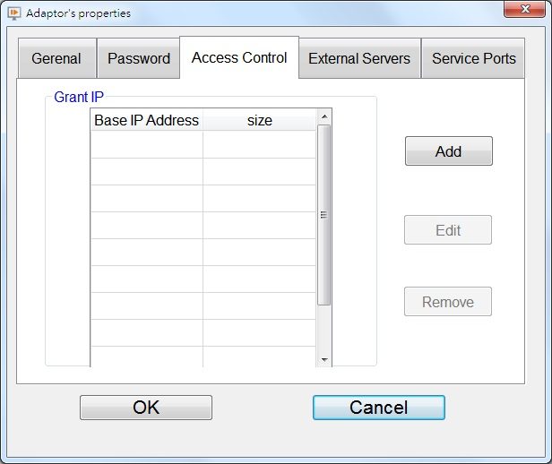
Figure 536 Access Control setting page of ethernet module
Table 302 properties of Access Setting Control page of ethernet module
|
Options |
Description |
|
【Base IP Address】 |
The smallest IP Address. |
|
【Size】 |
Continuous quantity. |
|
【Add】 |
Add an Authorization information. |
|
【Edit】 |
Edit an Authorization information |
|
【Remove】 |
Delete an Authorization information |
27.4.5 External Severs Setting Page of Ethernet Module
External Severs Setting Page of Ethernet Module on HMI, as shown below.
The meaning of each option is as follows, as shown in the following table, please refer to the PLC network Ethernet communication module operating instructions manual
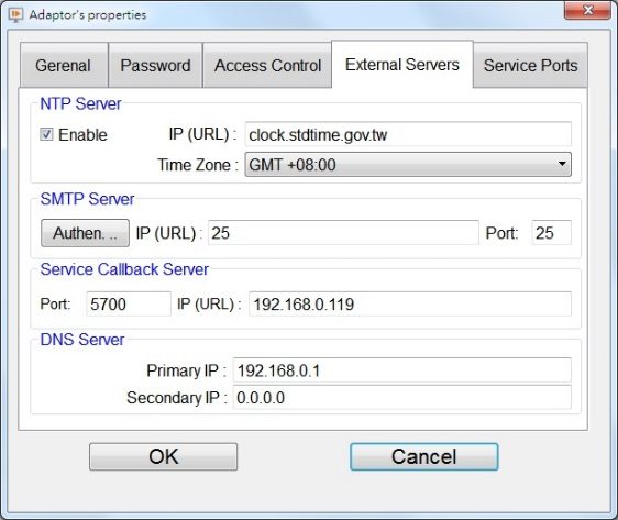
Figure 537 External Severs setting page of ethernet module
Table 303 properties of External Severs setting page of ethernet module
|
Options |
Description |
|
【NTP Server】 |
Network automation calibration time function. 【Enable】 Enable Network automation calibration time function. 【IP(URL)】 URL of NTP Sever 【Time Zone】 Location of the Time Zone |
|
【SMTP Server】 |
Function of sending Email 【IP(URL)】 URL of sending email sever. |
|
【Service CallBack Server】 |
Automatic maintenance callback function. 【Port】 Maintenance Center port number. 【IP(URL)】 Maintenance Center network address or domain name. |
|
【DNS Server】 |
Domain name sever 【Primary IP】 Primary DNS Server. 【Secondary IP】 Secondary DNS Server. |
27.4.6 Service Port Setting Page of Ethernet Module
Display service port setting page of ethernet module on HMI, as shown below.
The meaning of each option is as follows, as shown in the following table, please refer to the PLC network Ethernet communication module operating instructions manual
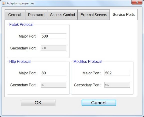
Figure 538 service port setting page of ethernet module
Table 304 properties of service port setting page of ethernet module
|
Option |
Description |
|
【Fatek Protocol】 |
FATEK communication protocol service port NO. |
|
【Http Protocol】 |
Http communication protocol service port NO. |
|
【Modbus Protocol】 |
Modbus communication protocol service port NO. |
27.5 Control PLC run/stop from HMI
This chapter will introduce how to control the PLC run or stop operation from HMI.
This function only supports for the FATEK PLC, it cannot use without FATEK PLC in the【Link】.
27.5.1 Setting the PLC run/stop function
Step1: drag a【Function Switch】from【Toolbox】【Lamp/Switch】to the screen.
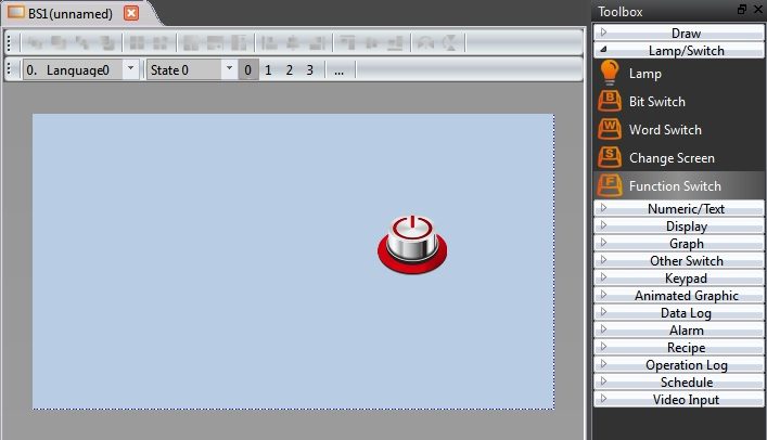
Figure 539 drag a【Function Switch】to the screen
Step2: double click the object to enter the properties setting page, select the【PLC: Run PLC】or【PLC: Stop PLC】option.
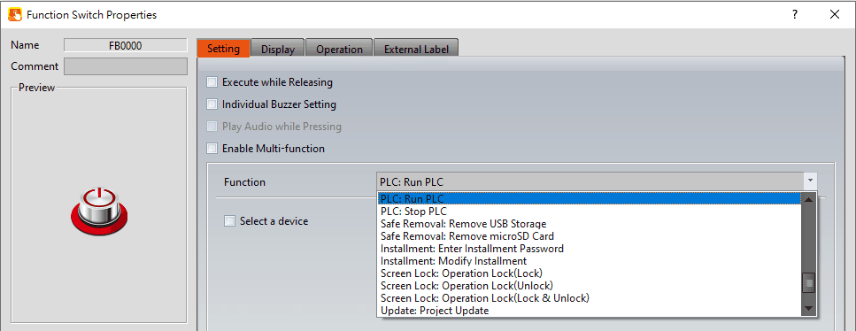
Figure 540 select run/stop PLC function
【Select a device】can use to directly control the specified PLC. If this option is not selected, then it will show the FATEK PLC link list to let the user choose which PLC to control.
27.5.2 PLC run/stop operation steps
If didn’t set the【Select a device】, then it will appear the following screen when pressing the button.
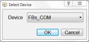
Figure 541 select the PLC device
Click the list and select the PLC to control.
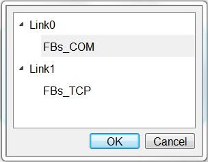
Figure 542 select the target PLC
Note: If using the PLC M1912 to stop the PLC, then cannot use this function switch to reboot the PLC.
27.6 Enable and Disable PLC from HMI
When the user wants to adjust the on-site equipment, but is not convenient to use the computer, you can plan the enabling and disabling points in the project in advance, so as to avoid false actions during the test. The following describes how to control from the HMI.
As shown in the figure below, when Y0 is disabled, we can’t get the signal from Y0 if we trigger M1.
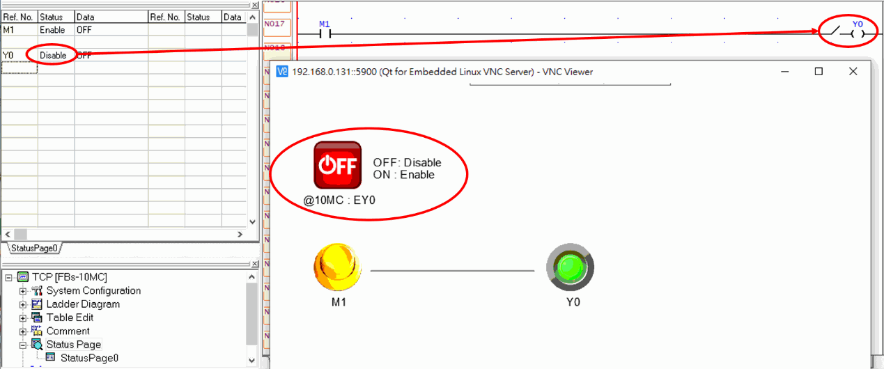
Figure 543 Disable illustration
On the contrary, when enabled, the output can get the signal
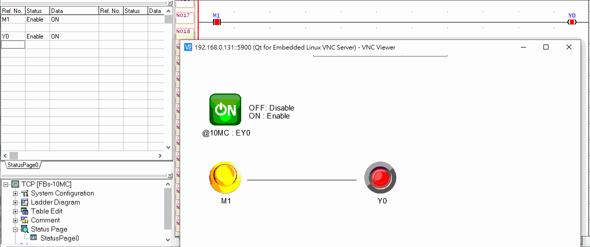
Figure 544 Enable illustration
The controlled address only supports X, Y, M, and S. It is supported the type start with E in the bit switch【Input Address】. The example is written as: @0:EY0
Tip: press ← → to switch chapters, Ctrl+K to search