【Multi-Link】function is to build multi-link master on FATEK HMI, other multi-link slaves on HMI can communicate with multi-link master, communicate with the【Destination Link】device which connect to the multi-link master. That is, the multi-link master communicate with【Destination Link】device it link with, multi-link slave connect with multi-link master, and get the data they need to display or setting through multi-link master. On the use of a multi-link master corresponding to a link to the【Destination Link】device; According the way to communicate with multi-link slave, multi-link master fall into two parts,【Multi-Link Master(Ethernet)】and【Multi-Link Master(Serial)】;【Multi-Link Master(Ethernet)】support【IP Address Filter】and【Operation Lock】functions
Specification and setting and other related information of the multi-link master please refer to the following.
Table 312 multi-link support number od slaves
|
Options |
Multi-Link Master (Ethernet) |
Multi-Link Master (Serial) |
|
Support the number of slaves |
32 |
8 |
|
Others |
support【IP Address Filter】function support【Operation Lock】function |
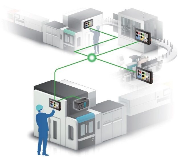
Figure 563 multi-link application diagram
29.1 【Multi-Link】 Setting
29.1.1 Serial
【Multi-Link】function support serial port to communicate with each other between master and slave. The following sections describe the settings for the master and slave serial ports.
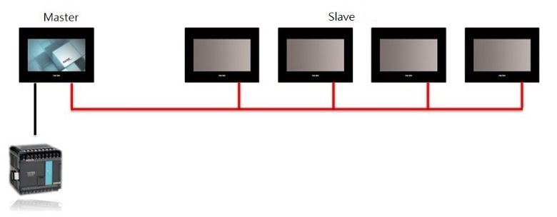
Figure 564 Multi-Link(Serial) connection diagram
Note : The connection between master and slave must be 422/485 in order to support more than 2 slaves. If 232 only support one
29.1.1.1 Multi-Link Master(Serial) setting
The serial port setting of the multi-link master, need to select【Interface Type】【Multi-Link Master(Serial)】in【New Link Property】dialog, as shown below, the setting meaning are as follows.
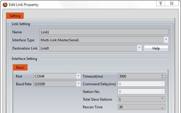
Figure 565【Multi-Link Master(Serial)】setting page
Table 313 properties of【Multi-Link Master(Serial)】
|
Options |
Description |
|
【Link Setting】 |
【Name】 Name of multi-link master 【Interface Type】 Interface Type of multi-link master 【Destination Link】 The destination link for the multi-link master, that is, the name of the PLC device to which the multi-link master is connected |
|
【Interface Setting】 |
【Port】 The port that multi-link master connect with, this port needs to connect with slave. 【Baud Rate】 Baud rate of multi-link master port, baud rate between multi-link master and slave needs to be the same, only support 38400, 57600 and 115200, etc. 【Timeout(ms)】 The waiting time before the connection is terminated when the communication between the multi-link master and slave is abnormal. 【Total Stations】 Number of slaves supported by multi-link master. 【Rescan Time】 Multi-link master excute scanning the interval time of online slaves. |
29.1.1.2 Multi-Link Slave(Serial) Setting
The serial port setting of the multi-link slave, need to select【Interface Type】【Multi-Link Slave(Serial)】in【New Link Property】dialog, as shown below, the setting meaning are as follows.
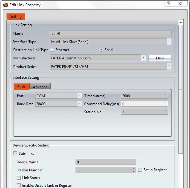
Figure 566【Multi-Link Slave(Serial)】setting page
Table 314 properties of【Multi-Link Slave(Serial)】
|
Options |
Description |
|
【Link Setting】 |
【Name】 Name of multi-link slave 【Interface Type】 Interface Type of multi-link slave 【Destination Link Type】 The destination link type of multi-link slave corresponding to the multi-link master 【Manufacturer】 The destination link manufacturer of multi-link slave corresponding to the multi-link master 【Product Series】 The destination link product series of multi-link slave corresponding to the multi-link master |
|
【Interface Setting】 |
【Port】 The port that multi-link slave connect with, this port needs to connect with master. 【Baud Rate】 Baud rate of multi-link master port, baud rate between multi-link master and slave needs to be the same, only support 38400, 57600 and 115200, etc. 【Timeout(ms)】 When a communication error occurs, wait time before terminating the connection and generating an error 【Station No.】 Station No. of multi-link slave. |
29.1.2 Ethernet
【Multi-Link】function support ethernet to communicate with each other between master and slave. The following sections describe the settings for the master and slave ethernet.
29.1.2.1 Multi-Link Master(Ethernet) setting
The serial port setting of the multi-link master, need to select【Interface Type】【Multi-Link Master(Ethernet)】in【New Link Property】dialog, as shown below, the setting meaning are as follows.
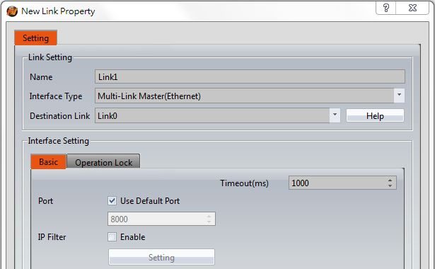
Figure 567【Multi-Link Master(Ethernet)】setting page
Table 315 properties of【Multi-Link Master(Ethernet)】setting
|
Options |
Description |
|
【Link Setting】 |
【Name】 Name of multi-link master 【Interface Type】 Interface Type of multi-link master 【Destination Link】 The destination link for the multi-link master, that is, the name of the PLC device to which the multi-link master is connected |
|
【Interface Setting】 |
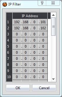
【Port】 The port that multi-link master connect with, the port setting needs to be the same with the slave; default port is 8000 【IP filter】 When enable, the multi-link master will only allow the IP of the slaves that on the list to connect with the master When enable, click【Setting】will appear dialog as shown below, set the IP Address in【IP Filter】of the slave that you want to connect with.
【Timeout(ms)】 The waiting time before the connection is terminated when the communication between the multi-link master and the slave is abnormal. |
29.1.2.2 Multi-Link Slave(Ethernet) setting
The serial port setting of the multi-link slave, need to select【Interface Type】【Multi-Link Slave(Ethernet)】in【New Link Property】dialog, as shown below, the setting meaning are as follows.
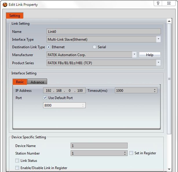
Figure 568【Multi-Link Slave(Ethernet)】setting page
Table 316 properties of【Multi-Link Slave(Ethernet)】setting
|
Options |
Description |
|
【Link Setting】 |
【Name】 Name of multi-link slave. 【Interface Type】 Interface Type of multi-link slave. 【Destination Link Type】 The destination link type of multi-link slave corresponding to the multi-link master 【Manufacturer】 The destination link manufacturer of multi-link slave corresponding to the multi-link master 【Product series】 The destination link product series of multi-link slave corresponding to the multi-link master |
|
【Interface Setting】 |
【IP Address】 IP Address of the slave that want to connect with the master. 【Port】 Multi-link slave connect to the ethernet port of the master 【Timeout(ms)】 When communication error occur, wait time before terminating and the connection and generating an error |
|
【Device specific setting】 |
The setting of this part needs to be the same with the device setting of the destination link of the multi-link master. |
29.2 Operation Lock
When the communication between the master and the slave of the【Multi-Link】function is used,【Operation Lock】function can be used on FATEK HMI, lock the other unused screen of FATEK HMI, to prevent the operation from the other FATEK HMI,to avoid the unexpected situation occurred.
29.2.1 Operation Lock Description
【Operation Lock】function need to be enabled at【Operation Lock】of the【Multi-Link Master(Ethernet)】link setting page, as shown Figure 567 below, there are two conditions to trigger【Operation Lock】, touch the HMI screen and press the【Function Switch】of the【Operation Lock(Unclock)】or【Operation Lock(Lock&Unclock)】; there are also two ways to unlock, it will automactically unlocked after the countdown is complete and press the【Function Switch】of the【Operation Lock(Unclock)】or【Operation Lock(Lock&Unclock)】, the setting options are as follows:
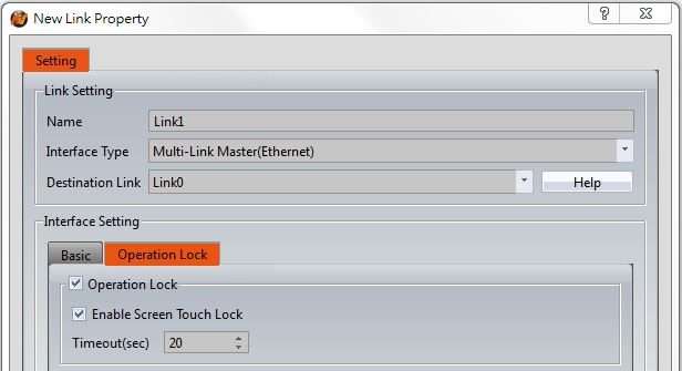
Figure 569 setting page【Operation Lock】
Table 317 properties of【Operation Lock】setting
|
Options |
Description |
|
【Operation Lock】 |
【Enable Screen Touch Lock】 When enabled, touch the HMI screen to enable【Operation Lock】, the other multi-link HMI will go into the screen lock status. 【Timeout(sec)】 After HMI in screen lock status, if the enable【Operation Lock】HMI doesn’t operate exceed the setting time, then the other multi-link HMI in the screen lock status will automactically unlock the screen. |
29.3 Multi-Link Eaxmple
This section explains how to build multi-link, and multi-link master communication with FATEK PLC, communication with slave by using serial, in this example the master use P5070N, the salve use P5043N, setting steps as follows.
Step 1: Build the new project of the master and build link 0, select Fatek FBs/B1/B1z/HB1 driver, please refer to other relevant sections for this section.
Step 2: Add link 1,【Interface Type】choose multi-link master(serial),【Destination Link】choose link 0,【Port】choose COM4(COM4 RS485 of the P5070N) and link with the multi-link slave,【Baud Rate】choose 115200,【Total Stations】choose 1 link with a slave, figure as shown belown.
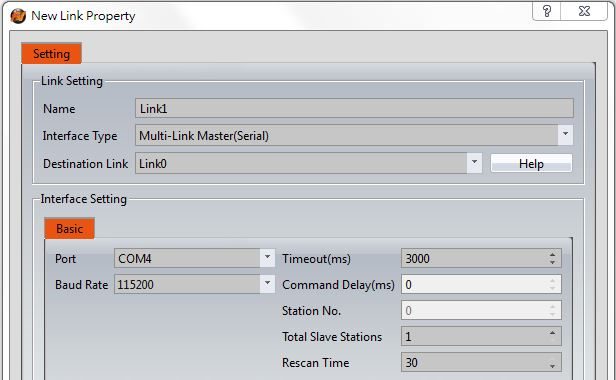
Figure 570 setting page of multi-link master
Step 3: Planning 6【Numeric Input/Display】objects on the master screen,【Monitor Address】set as @0:R0 ~ @0:R5.
Step 4: build a new project of the slave,【Interface Type】choose multi-link slave(serial),【Destination Link Type】choose serial,【Port】choose COM3(COM3 RS485 of the P5043N) and link with the multi-link slave,【Baud Rate】choose 115200,【Total Stations】choose 1, figure as shown belown.
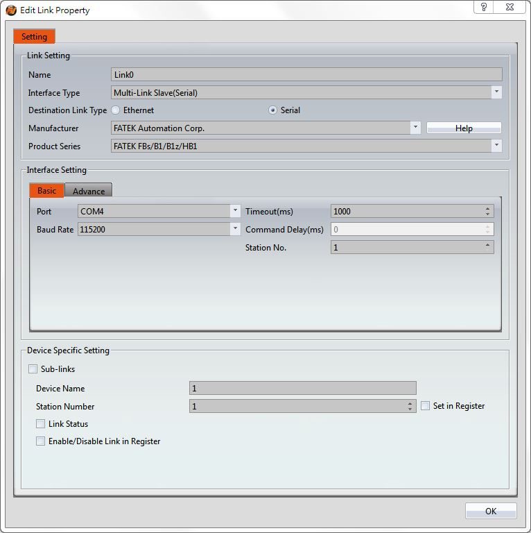
Figure 571 setting page of multi-link slave
Step 5: Planning 6【Numeric Input/Display】objects on the master screen,【Monitor Address】set as @1:R0 ~ @1:R5.
Step 6: Download the project to master and slave HMI, and link with the FATEK PLC master and master COM4(RS485) and slave COM3(RS485), input the value in master and the slave will synchronize update, or input the value in slave and the master will synchronize update.
Tip: press ← → to switch chapters, Ctrl+K to search